

The block-diagram of algorithm of calculation according to mathematical model
The block-diagram of algorithm of calculation is given in figure 4.4.
The task for fulfillment
· Make the program realizing developed algorithm;
· Include into the program the operators, allowing carry out verification of calculation results;
· Organize a graphical output of the calculated functions of currents and voltages;
· Debug the program;
· Save the results of the work (the program, listing of calculation, graphics) into a personal file.

Figure 4.4 – The block-diagram of algorithm of calculation of transient
5 LAboratory work # 5
TOPIC: Calculation of transients in linear electric circuits by numerical method. Part 2.
PURPOSE OF THE WORK: Practice of applying of method of state variable, numerical methods of integration of the differential equations and discrete current models of inductive and capacitor elements in backward Euler method for calculations of transients.___________________________________________________
The task for fulfillment
Create mathematical model realizing calculation branch transient currents beginning at the moment of switch shorting for your individual task;
Develop algorithm according to created mathematical model by means backward Euler method;
Make the program realizing developed algorithm;
Include into the program the operators, allowing carry out verification of calculation results;
Organize a graphical output of the calculated functions of currents and voltages;
Debug the program;
Save the results of the work (the program, listing of calculation, graphics) at your personal file.
Individual tasks
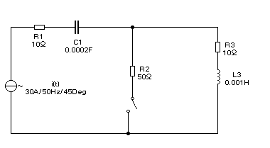
Variant 1:

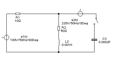
Variant 2:

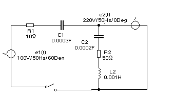
Variant 3:

Variant 4:

Variant 5:

Variant 6:

Variant 7:

Variant 8:

Variant 9:

Variant 10:
Variant 11:

Variant 12:

Variant 13:
![]()
Variant 14:

Variant 15:

Variant 16:
Variant 17:

Variant 18:

Variant 19:
Variant 20:

Variant 21:

Variant 22:

Variant 23:

6 LAboratory work # 6
TOPIC: Modeling of steady state processes in nonlinear electric circuits of direct current by numerical method in MATLAB environment. Part 1.
PURPOSE OF THE WORK: Problem statement, development of the program of calculation of electrical state in the simple nonlinear circuit of a direct current by the Newton method.__________________
Mathematical model
Let’s consider the example of the mathematical model development of the electric processes in the circuit represented in the figure 6.1 and analyze of them in MATLAB environment.

Figure 6.1 – Given electrical circuit
Let parameters values of elements are given as:
EMF – E= 10 V;
Linear resistance – R1=0.5 Ohm;
Nonlinear resistance Rn is given analytically accord to VACH:
Un=a·I⅓, (6.1)
where Un – voltage across of nonlinear resistor, a=4.
It is require the determination of the current through the given circuit.
Then accord to second Kirchhoff law the equation is as following:
R1·I+ Un =E. (6.2)
Let’s substitute Un into the above represented equation and the nonlinear algebraic equation concerning the current I is obtained:
R1·I+a·I⅓=E. (6.3)
This equation would be written down as f(I)= 0, where
f(I)= R1·I+ a·I⅓ -E. (6.4)
Accord to the Newton algorithm k+1 approach could be found as:
![]() .
(6.5)
.
(6.5)
Expression for determination of f'(I) could be obtained from (6.4):
f'(I)=R1+a/(3·I⅔).