

17
c h a p t e r 3
Nonadaptive Direction of
Arrival Estimation
3.1CLASSICAL METHODS FOR DIRECTION OF ARRIVAL ESTIMATION
Classical direction of arrival (DOA) methods are essentially based on beamforming. The two classical techniques for DOA are the delay-and-sum method and the minimum variance distortionless response (MVDR) [2] method. The basic idea behind the classical methods is to scan a beam through space and measure the power received from each direction. Directions from which the largest amount of power is received are taken to be the DOAs.
3.1.1 Delay-and-Sum Method
The delay-and-sum method computes the DOA by measuring the signal power at each possible angle of arrival and selecting as the estimate of the angle of arrival the direction of maximum power [8]. The power from a particular direction is measured by first forming a beam in that direction and setting the beamformer weights equal to the steering vector corresponding to that particular direction. The output power of the beamformer using this method is given by:
P(θ) = E[yHy] = E|wHxn|2 = E|a(θ)Hxn|2 = a(θ)HRxxa(θ). |
(3.1) |
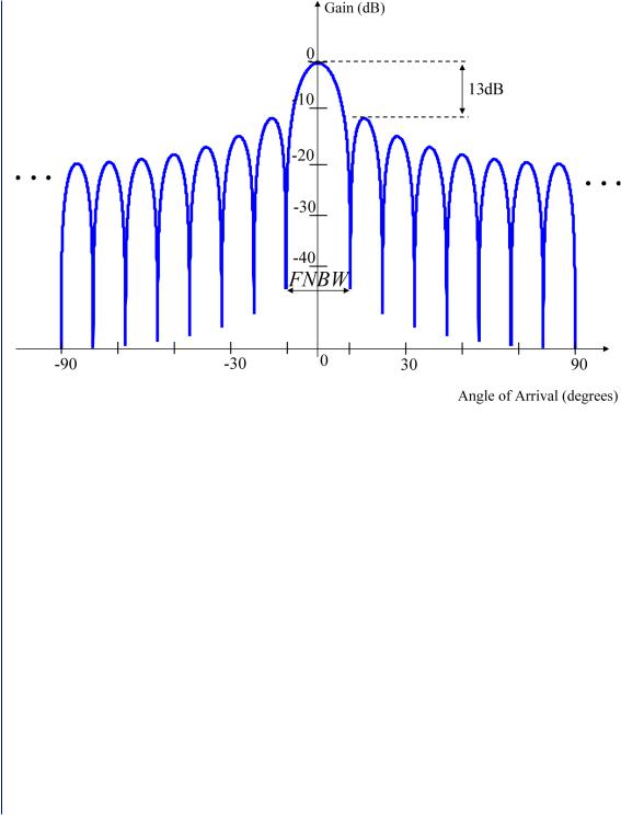
P(θ) will have peaks when w is equal to the steering vectors corresponding to the incoming signals. The disadvantage of this method is that the only way to improve the DOA resolution is to increase the number of antenna elements in the array. As was previously mentioned, the classical methods are inferior to the high-resolution subspace techniques because they do not make use of the subspace decomposition described in Chapter 2. In a linear array, the elements of the steering vectors have gains of equal magnitude, the weight vector w produces a sinc beampattern that has large sidelobes (see Figure 3.1). In fact, the beampattern has the same shape as the discrete time Fourier transform (DTFT) of a rectangular window. The largest sidelobe has a magnitude that is only 13 dB below that of the mainlobe. Despite the narrow mainlobe width, the large sidelobes
18 NARROWBAND DIRECTION OF ARRIVAL ESTIMATION FOR ANTENNA ARRAYS
Figure 3.1: Beam associated with equal magnitude gains for a linear array.
allow unwanted power to enter into the computation of P(θ) for different angles of arrival and hence DOA resolution deteriorates. This method uses all the degrees of freedom to choose the weight vector with the narrowest possible beam in the direction from which the power is to be measured [15].
3.1.2 Capon’s Minimum Variance Distortionless Response Method
Capon’s minimum variance or MVDR was proposed in [3]. This method is similar to the delay-and- sum technique described in the previous section in that it measures the power of the received signal in all possible directions. The power from the DOA, θ, is measured by constraining the beamformer gain to be 1 in that direction and using the remaining degrees of freedom to minimize the contributions to the output power from signals coming from all other directions. The problem can be stated mathematically as a constrained minimization process. The idea is that for each possible angle, θ, the signal power in (3.2) is minimized with respect to w subject to the constraint that wHa(θ) = 1.
min E[|y(k)|2 |
] = min wH Rw. |
(3.2) |
w |
w |
|
Nonadaptive Direction of Arrival Estimation 19
The angles for which (3.2) has peaks represent estimates of the angles of arrival of the signals. The solution to the constrained optimization problem is known as the MVDR beamformer [16] and its weights are given by:
w = |
R−1 a(θ) |
|
a(θ)R−1 a(θ). |
(3.3) |
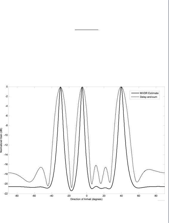
The disadvantage of this method is that an inverse matrix computation is required which may become ill-conditioned if highly correlated signals are present. This method, however, provides higher resolution than the delay-and-sum beamformer. A simulation of the MVDR and delay-and- sum methods is shown is Figure 3.2. In this simulation, a 10-element uniform linear array is used
Figure 3.2: DOA estimation simulation for a 10-element uniform linear array. The MVDR estimator is plotted with a solid line and delay-and-sum with a dotted line. Three signals are present and the SNR is 0 dB. D = λ /2.