

2016_FSAE_Rules
.pdfNOTE: Cables, wires, hoses, tubes, etc. must not impede the passage of the templates required by T4.1.1 and T4.2.
T4.3 Driver’s Seat
T4.3.1 The lowest point of the driver’s seat must be no lower than the bottom surface of the lower frame rails or by having a longitudinal tube (or tubes) that meets the requirements for Side Impact tubing, passing underneath the lowest point of the seat.
T4.3.2 When seated in the normal driving position, adequate heat insulation must be provided to ensure that the driver will not contact any metal or other materials which may become heated to a surface temperature above sixty degrees C (60°C). The insulation may be external to the cockpit or incorporated with the driver’s seat or firewall. The design must show evidence of addressing all three
(3) types of heat transfer, namely conduction, convection and radiation, with the following between the heat source, e.g. an exhaust pipe or coolant hose/tube and the panel that the driver could contact, e.g. the seat or floor:
a.Conduction Isolation by:
i.No direct contact between the heat source and the panel, or
ii.A heat resistant, conduction isolation material with a minimum thickness of 8 mm (0.3 in) between the heat source and the panel.
b.Convection Isolation by a minimum air gap of 25 mm (1 inch) between the heat source and the panel
c.Radiation Isolation by:
i.A solid metal heat shield with a minimum thickness of 0.4 mm (0.015 in) or
ii.Reflective foil or tape when combined with T4.3.2.a.ii above.
T4.4 Floor Close-out
All vehicles must have a floor closeout made of one or more panels, which separate the driver from the pavement. If multiple panels are used, gaps between panels are not to exceed 3 mm (1/8 inch). The closeout must extend from the foot area to the firewall and prevent track debris from entering the car. The panels must be made of a solid, non-brittle material.
T4.5 Firewall
T4.5.1 A firewall must separate the driver compartment from all components of the fuel supply, the engine oil, the liquid cooling systems and any high voltage system (PART EV - EV1.1). It must protect the neck of the tallest driver. It must extend sufficiently far upwards and/or rearwards such that any point less than 100 mm (4 ins.) above the bottom of the helmet of the tallest driver shall not be in direct line of sight with any part of the fuel system, the cooling system or the engine oil system.
T4.5.2 The firewall must be a non-permeable surface made from a rigid, fire resistant material.
T4.5.3 Any firewall must seal completely against the passage of fluids, especially at the sides and the floor of the cockpit, i.e. there can be no holes in a firewall through which seat belts pass.
T4.5.4 Pass-through for wiring, cables, etc. are allowable if grommets are used to seal the pass-through. Also, multiple panels may be used to form the firewall but must be sealed at the joints.
EV CARS ONLY
In addition a firewall must separate the driver compartment from all tractive system components. NOTE: this includes any HV wiring.
|
51 |
© 2015 SAE International. All Rights Reserved |
2016 Formula SAE® Rules – May 11, 2015 |

The tractive system firewall must be composed of two layers:
a.One layer, facing the tractive system side, must be made of aluminum with a thickness between 0.5 and 0.7 mm. This part of the tractive system firewall must be grounded according to FSAE Rule PART EV - EV4.3.
b.The second layer, facing the driver, must be made of an electrically insulating material. The material used for the second layer must meet UL94-V0, FAR25 or equivalent. The second layer must not be made of CFRP.
c.The thickness of second layer must be sufficient to prevent penetrating this layer with a 4 mm wide screwdriver and 250N of force. The firewall must be rigidly mounted.
|
For tractive system firewalls, a sample of the firewall must be presented at technical inspection. |
|
Conductive parts (except for the chassis) may not protrude through the firewall or must be properly |
|
insulated, see requirements above, on the driver side. |
T4.6 |
Accessibility of Controls |
|
All vehicle controls, including the shifter, must be operated from inside the cockpit without any part |
|
of the driver, e.g. hands, arms or elbows, being outside the planes of the Side Impact Structure defined |
|
in Rule T3.24 and T3.33. |
T4.7 |
Driver Visibility |
T4.7.1 |
General Requirement |
|
The driver must have adequate visibility to the front and sides of the car. With the driver seated in a |
|
normal driving position he/she must have a minimum field of vision of two hundred degrees (200°) (a |
|
minimum one hundred degrees (100°) to either side of the driver). The required visibility may be |
|
obtained by the driver turning his/her head and/or the use of mirrors. |
T4.7.2 |
Mirrors |
|
If mirrors are required to meet Rule T4.7.1, they must remain in place and adjusted to enable the |
|
required visibility throughout all dynamic events. |
T4.8 |
Driver Egress |
|
All drivers must be able to exit to the side of the vehicle in no more than 5 seconds. Egress time |
|
begins with the driver in the fully seated position, hands in driving position on the connected steering |
|
wheel and wearing the required driver equipment. Egress time will stop when the driver has both feet |
|
on the pavement. |
ARTICLE 5: DRIVERS EQUIPMENT (BELTS AND COCKPIT PADDING)
T5.1 Belts - General
T5.1.1 Definitions
a.A 5-point system – consists of a 76 mm (3 inch) wide lap belt, approximately 76 mm (3 inch) wide shoulder straps and a single approximately 51 mm (2 inch) wide anti-submarine strap. The single anti-submarine strap must have a metal-to-metal connection with the single release common to the lap belt and shoulder harness.
b.A 6-point system – consists of a 76 mm (3 inch) wide lap belt, approximately 76 mm (3 inch) wide shoulder straps and two (2) approximately 51 mm (2 inch) wide leg or anti-submarine straps.
c.A 7-point system – system is the same as the 6-point except it has three (3) anti-submarine straps, two (2) from the 6-point system and one (1) from the 5-point system.
|
52 |
© 2015 SAE International. All Rights Reserved |
2016 Formula SAE® Rules – May 11, 2015 |

NOTE: 6 and 7-point harnesses to FIA specification 8853/98 and/or SFI Specification 16.5 with approximately 51 mm (2 inch) lap belts are acceptable.
d.An “upright driving position” is defined as one with a seat back angled at thirty degrees (30°) or less from the vertical as measured along the line joining the two 200 mm circles of the template of the 95th percentile male as defined in Rule Error! Reference source not found. and positioned per T3.10.4.
e.A “reclined driving position” is defined as one with a seat back angled at more than thirty degrees (30°) from the vertical as measured along the line joining the two 200 mm circles of the template of the 95th percentile male as defined in Rule T3.10.3 and positioned per T3.10.4.
f.The “chest-groin line” is the straight line that in side view follows the line of the shoulder belts from the chest to the release buckle.
T5.1.2 Harness Requirements
All drivers must use a 5, 6 or 7 point restraint harness meeting the following specifications:
a.All driver restraint systems must meet SFI Specification 16.1, SFI Specification 16.5, or FIA specification 8853/98.
b.The belts must bear the appropriate dated labels.
c.The material of all straps must be in perfect condition.
d.There must be a single release common to the lap belt and shoulder harness using a metal-to- metal quick release type latch.
e.To accommodate drivers of differing builds, all lap belts must incorporate a tilt lock adjuster (“quick adjuster”). A tilt lock adjuster in each portion of the lap belt is highly recommended.
Lap belts with “pull-up” adjusters are recommended over “pull-down” adjusters.
f.Cars with a “reclined driving position” (see 5.1.1.e above) must have either a 6 point or 7-point harness, AND have either anti-submarine belts with tilt lock adjusters (“quick adjusters”) or have two (2) sets of anti-submarine belts installed.
g.The shoulder harness must be the over-the-shoulder type. Only separate shoulder straps are permitted (i.e. “y”-type shoulder straps are not allowed). The “H”-type configuration is allowed.
h.It is mandatory that the shoulder harness, where it passes over the shoulders, be 76 mm (3 inch) wide, except as noted below. The shoulder harness straps must be threaded through the three bar adjusters in accordance with manufacturer’s instructions.
i.When the HANS device is used by the driver, FIA certified 51 mm (2 inch) wide shoulder harnesses are allowed. Should a driver, at any time not utilize the HANS device, then 76 mm (3 inch) wide shoulder harnesses are required.
T5.1.3 Harness Replacement
SFI spec harnesses must be replaced following December 31st of the 2nd year after the date of manufacture as indicated by the label. FIA spec harnesses must be replaced following December 31st of the year marked on the label.
NOTE: FIA belts are normally certified for five (5) years from the date of manufacture.
T5.1.4 The restraint system must be worn tightly at all times.
T5.2 Belt, Strap and Harness Installation - General
T5.2.1 The lap belt, shoulder harness and anti-submarine strap(s) must be securely mounted to the Primary Structure. Such structure and any guide or support for the belts must meet the minimum requirements of T3.4.1.
NOTE: Rule T3.5.5 applies to these tubes as well so a non-straight shoulder harness bar would require support per T3.5.5
|
53 |
© 2015 SAE International. All Rights Reserved |
2016 Formula SAE® Rules – May 11, 2015 |

T5.2.2 The tab or bracket to which any harness is attached must have:
a.A minimum cross sectional area of 60 sq. mm (0.093 sq. in) of steel to be sheared or failed in tension at any point of the tab, and
b.A minimum thickness of 1.6 mm (0.063 inch).
c.Where lap belts and anti-submarine belts use the same attachment point, a minimum cross sectional area of 90 sq. mm (0.140 sq. in) of steel to be sheared if failed in tension at any point of the tab.
d.Where brackets are fastened to the chassis, two fasteners of 6mm Metric Grade 8.8 (1/4 inch SAE Grade 5) fasteners or stronger must be used.
|
NOTE: Double shear mounting is preferred. |
T5.2.3 |
Harnesses, belts and straps must not pass through a firewall, i.e. all harness attachment points must |
|
be on the driver’s side of any firewall. |
T5.2.4 |
The attachment of the Driver’s Restraint System to a monocoque structure requires an approved |
|
Structural Equivalency Spreadsheet per Rule T3.9. |
T5.2.5 |
The restraint system installation is subject to approval of the Chief Technical Inspector. |
T5.3 Lap Belt Mounting
T5.3.1 The lap belt must pass around the pelvic area below the Anterior Superior Iliac Spines (the hip bones).
T5.3.2 The lap belts should not be routed over the sides of the seat. The lap belts should come through the seat at the bottom of the sides of the seat to maximize the wrap of the pelvic surface and continue in a straight line to the anchorage point.
T5.3.3 Where the belts or harness pass through a hole in the seat, the seat must be rolled or grommeted to prevent chafing of the belts.
T5.3.4 To fit drivers of differing statures correctly, in side view, the lap belt must be capable of pivoting freely by using either a shouldered bolt or an eye bolt attachment, i.e. mounting lap belts by wrapping them around frame tubes is no longer acceptable.
T5.3.5 With an “upright driving position”, in side view the lap belt must be at an angle of between forty-five degrees (45°) and sixty-five degrees (65°) to the horizontal. This means that the centerline of the lap belt at the seat bottom should be between 0 – 76 mm (0 – 3 inches) forward of the seat back to seat bottom junction. (See Figure 10)
|
54 |
© 2015 SAE International. All Rights Reserved |
2016 Formula SAE® Rules – May 11, 2015 |

T5.3.6 With a “reclined driving position”, in side view the lap belt must be between an angle of sixty degrees
(60°) and eighty degrees (80°) to the horizontal.
T5.4 Shoulder Harness
T5.4.1 The shoulder harness must be mounted behind the driver to structure that meets the requirements of T3.4.1. However, it cannot be mounted to the Main Roll Hoop Bracing or attendant structure without additional bracing to prevent loads being transferred into the Main Hoop Bracing.
T5.4.2 If the harness is mounted to a tube that is not straight, the joints between this tube and the structure to which it is mounted must be reinforced in side view by triangulation tubes to prevent torsional rotation of the harness mounting tube. Supporting calculations are required. Analysis Method: Use 7kN load per attachment and the range of angles in T5.4.5 calculate that the bent Shoulder Harness Bar triangulation stresses are less than As Welded Yield Strength (T3.4.1 note 4) for combined bending and shear and does not fail in column buckling. If the team chooses not to perform the strength analysis rule T3.5.5 will apply.
T5.4.3 The strength of any shoulder harness bar bracing tubes must be proved in the relevant tab of the team’s SES submission.
T5.4.4 The shoulder harness mounting points must be between 178 mm (7 inches) and 229 mm (9 inches) apart. (See Figure 11)
|
55 |
© 2015 SAE International. All Rights Reserved |
2016 Formula SAE® Rules – May 11, 2015 |
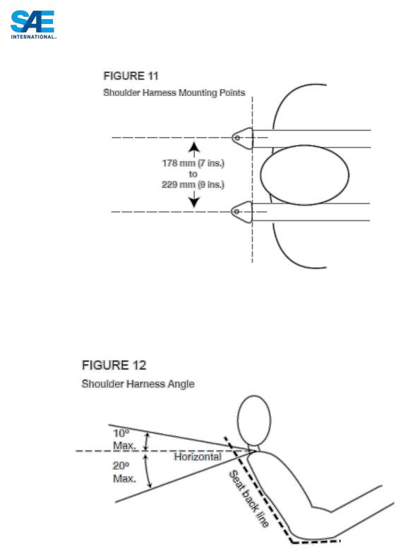
T5.4.5 From the driver’s shoulders rearwards to the mounting point or structural guide, the shoulder harness must be between ten degrees (10°) above the horizontal and twenty degrees (20°) below the horizontal. (See Figure 12).
T5.5 Anti-Submarine Belt Mounting
T5.5.1 The anti-submarine belt of a 5 point harness should be mounted in line with, or angled slightly forward (up to twenty degrees (20°)) of, the driver’s chest-groin line.
T5.5.2 The anti-submarine belts of a 6 point harness should be mounted either:
a.With the belts going vertically down from the groin, or angled up to twenty degrees (20°) rearwards. The anchorage points should be approximately 100 mm (4 inches) apart. Or
|
56 |
© 2015 SAE International. All Rights Reserved |
2016 Formula SAE® Rules – May 11, 2015 |

b.With the anchorage points on the Primary Structure at or near the lap belt anchorages, the driver sitting on the anti-submarine belts, and the belts coming up around the groin to the release buckle.
T5.6 Head Restraint
T5.6.1 A head restraint must be provided on the car to limit the rearward motion of the driver’s head.
T5.6.2 The restraint must:
a.Be vertical or near vertical in side view.
b.Be padded with an energy absorbing material such as Ethafoam® or Ensolite® with a minimum thickness of 38 mm (1.5 inches).
c.Have a minimum width of 15 cms (6 inches).
d.Have a minimum area of 235 sq. cms (36 sq. inches) AND have a minimum height adjustment of 17.5 cms (7 inches), OR have a minimum height of 28 cms (11 inches).
e.Be located so that for each driver:
i.The restraint is no more than 25 mm (1 inch) away from the back of the driver’s helmet, with the driver in their normal driving position.
ii.The contact point of the back of the driver’s helmet on the head restraint is no less than
50 mm (2 inch) from any edge of the head restraint.
NOTE 1: Head restraints may be changed to accommodate different drivers (See T1.2.2). NOTE 2: The above requirements must be met for all drivers.
NOTE 3: Approximately 100mm (4”) longitudinal adjustment is required to accommodate 5th to
95th Percentile drivers. This is not a specific rules requirement, but teams must have sufficient longitudinal adjustment and/or alternative thickness head restraints available, such that the above requirements are met by all their drivers.
T5.6.3 The restraint, its attachment and mounting must be strong enough to withstand a force of 890 Newtons (200 lbs. force) applied in a rearward direction.
T5.7 Roll Bar Padding
Any portion of the roll bar, roll bar bracing or frame which might be contacted by the driver’s helmet must be covered with a minimum thickness of 12 mm (0.5 inch) of padding which meets SFI spec 45.1 or FIA 8857-2001.
T5.8 Driver’s Leg Protection
T5.8.1 To keep the driver’s legs away from moving or sharp components, all moving suspension and steering components, and other sharp edges inside the cockpit between the front roll hoop and a vertical plane 100 mm (4 inches) rearward of the pedals, must be shielded with a shield made of a solid material. Moving components include, but are not limited to springs, shock absorbers, rocker arms, antiroll/sway bars, steering racks and steering column CV joints.
T5.8.2 Covers over suspension and steering components must be removable to allow inspection of the mounting points.
ARTICLE 6: GENERAL CHASSIS RULES |
|
|
T6.1 |
Suspension |
|
T6.1.1 |
The car must be equipped with a fully operational suspension system with shock absorbers, front and |
|
|
rear, with usable wheel travel of at least 50.8 mm (2 inches), 25.4 mm (1 inch) jounce and 25.4 mm (1 |
|
|
|
57 |
© 2015 SAE International. All Rights Reserved |
2016 Formula SAE® Rules – May 11, 2015 |
|

inch) rebound, with driver seated. The judges reserve the right to disqualify cars which do not represent a serious attempt at an operational suspension system or which demonstrate handling inappropriate for an autocross circuit.
T6.1.2 All suspension mounting points must be visible at Technical Inspection, either by direct view or by removing any covers.
T6.2 Ground Clearance
Ground clearance must be sufficient to prevent any portion of the car, other than the tires, from touching the ground during track events. Intentional or excessive ground contact of any portion of the car other than the tires will forfeit a run or an entire dynamic event.
Comment: The intention of this rule is that sliding skirts or other devices that by design, fabrication or as a consequence of moving, contact the track surface are prohibited and any unintended contact with the ground which either causes damage, or in the opinion of the ‘dynamic event organizers’ could result in damage to the track, will result in forfeit of a run or an entire dynamic event
T6.3 Wheels
T6.3.1 The wheels of the car must be 203.2 mm (8.0 inches) or more in diameter.
T6.3.2 Any wheel mounting system that uses a single retaining nut must incorporate a device to retain the nut and the wheel in the event that the nut loosens. A second nut (“jam nut”) does not meet these requirements.
T6.3.3 Standard wheel lug bolts are considered engineering fasteners and any modification will be subject to extra scrutiny during technical inspection. Teams using modified lug bolts or custom designs will be required to provide proof that good engineering practices have been followed in their design.
T6.3.4 Aluminum wheel nuts may be used, but they must be hard anodized and in pristine condition.
T6.4 Tires
T6.4.1 Vehicles may have two types of tires as follows:
a.Dry Tires – The tires on the vehicle when it is presented for technical inspection are defined as its “Dry Tires”. The dry tires may be any size or type. They may be slicks or treaded.
b.Rain Tires – Rain tires may be any size or type of treaded or grooved tire provided:
i.The tread pattern or grooves were molded in by the tire manufacturer, or were cut by the tire manufacturer or his appointed agent. Any grooves that have been cut must have documentary proof that it was done in accordance with these rules.
ii.There is a minimum tread depth of 2.4 mms (3/32 inch).
NOTE: Hand cutting, grooving or modification of the tires by the teams is specifically prohibited.
T6.4.2 Within each tire set, the tire compound or size, or wheel type or size may not be changed after static judging has begun. Tire warmers are not allowed. No traction enhancers may be applied to the tires after the static judging has begun, or at any time on-site at the competition.
NOTE: Due to the hazardous nature (significant health effects) of some traction modifier ingredients, teams are advised to closely follow manufacturers recommended procedures for safely handling and use of traction modifiers, if used before competition.
|
58 |
© 2015 SAE International. All Rights Reserved |
2016 Formula SAE® Rules – May 11, 2015 |

T6.5 Steering
T6.5.1 The steering wheel must be mechanically connected to the front wheels, i.e. “steer-by-wire” or electrically actuated steering of the front wheels, is prohibited.
T6.5.2 The steering system must have positive steering stops that prevent the steering linkages from locking up (the inversion of a four-bar linkage at one of the pivots). The stops may be placed on the uprights or on the rack and must prevent the tires from contacting suspension, body, or frame members during the track events.
T6.5.3 Allowable steering system free play is limited to seven degrees (7°) total measured at the steering wheel.
T6.5.4 The steering wheel must be attached to the column with a quick disconnect. The driver must be able to operate the quick disconnect while in the normal driving position with gloves on.
T6.5.5 Rear wheel steering, which can be electrically actuated, is permitted but only if mechanical stops limit the range of angular movement of the rear wheels to a maximum of six degrees (6°). This must be demonstrated with a driver in the car and the team must provide the facility for the steering angle range to be verified at Technical Inspection.
T6.5.6 The steering wheel must have a continuous perimeter that is near circular or near oval, i.e. the outer perimeter profile can have some straight sections, but no concave sections. “H”, “Figure 8”, or cutout wheels are not allowed.
T6.5.7 In any angular position, the top of the steering wheel must be no higher than the top-most surface of the Front Hoop. See Figure 3.
T6.5.8 Steering systems using cables for actuation are not prohibited by T6.5.1 but additional documentation must be submitted. The team must submit a failure modes and effects analysis report with design details of the proposed system as part of the structural equivalency spreadsheet (SES) or structural requirements certification form (SRCF). The report must outline the analysis that was done to show the steering system will function properly, potential failure modes and the effects of each failure mode and finally failure mitigation strategies used by the team. The organizing committee will review the submission and advise the team if the design is approved. If not approved, a non-cable based steering system must be used instead.
T6.5.9 The steering rack must be mechanically attached to the frame; if fasteners are used they must be compliant with Rule T11.2.
T6.5.10 Joints between all components attaching the steering wheel to the steering rack must be mechanical and be visible at Tech Inspection. Bonded joints without a mechanical backup are not permitted.
T6.6 Jacking Point
T6.6.1 A jacking point, which is capable of supporting the car’s weight and of engaging the organizers’ “quick jacks”, must be provided at the rear of the car.
T6.6.2 The jacking point is required to be:
a.Visible to a person standing 1 meter (3 feet) behind the car.
b.Painted orange.
c.Oriented horizontally and perpendicular to the centerline of the car
d.Made from round, 25 – 29 mm (1 – 1 1/8 inch) O.D. aluminum or steel tube
e.A minimum of 300 mm (12 inches) long
|
59 |
© 2015 SAE International. All Rights Reserved |
2016 Formula SAE® Rules – May 11, 2015 |

f.Exposed around the lower 180 degrees (180°) of its circumference over a minimum length of 280 mm (11 in)
g.The height of the tube is required to be such that:
i.There is a minimum of 75 mm (3 in) clearance from the bottom of the tube to the ground measured at tech inspection.
ii.With the bottom of the tube 200 mm (7.9 in) above ground, the wheels do not touch the ground when they are in full rebound.
h.Access from the rear of the tube must be unobstructed for at least 300mm of its length
Comment on Disabled Cars – The organizers and the Rules Committee remind teams that cars disabled on course must be removed as quickly as possible. A variety of tools may be used to move disabled cars including quick jacks, dollies of different types, tow ropes and occasionally even boards. We expect cars to be strong enough to be easily moved without damage. Speed is important in clearing the course and although the course crew exercises due care, parts of a vehicle can be damaged during removal. The organizers are not responsible for damage that occurs when moving disabled vehicles. Removal/recovery workers will jack, lift, carry or tow the car at whatever points they find easiest to access. Accordingly, we advise teams to consider the strength and location of all obvious jacking, lifting and towing points during the design process.
T6.7 Rollover Stability
T6.7.1 The track and center of gravity of the car must combine to provide adequate rollover stability.
T6.7.2 Rollover stability will be evaluated on a tilt table using a pass/fail test. The vehicle must not roll when tilted at an angle of sixty degrees (60°) to the horizontal in either direction, corresponding to 1.7 G’s.
The tilt test will be conducted with the tallest driver in the normal driving position.
ARTICLE 7: BRAKE SYSTEM
T7.1 Brake System - General
The car must be equipped with a braking system that acts on all four wheels and is operated by a single control.
T7.1.1 It must have two (2) independent hydraulic circuits such that in the case of a leak or failure at any point in the system, effective braking power is maintained on at least two (2) wheels. Each hydraulic circuit must have its own fluid reserve, either by the use of separate reservoirs or by the use of a dammed, OEM-style reservoir.
T7.1.2 A single brake acting on a limited-slip differential is acceptable.
T7.1.3 The brake system must be capable of locking all four (4) wheels during the test specified below. T7.1.4 “Brake-by-wire” systems are prohibited.
T7.1.5 Unarmored plastic brake lines are prohibited.
T7.1.6 The braking systems must be protected with scatter shields from failure of the drive train (see T8.4) or from minor collisions.
T7.1.7 In side view no portion of the brake system that is mounted on the sprung part of the car can project below the lower surface of the frame or the monocoque, whichever is applicable.
|
60 |
© 2015 SAE International. All Rights Reserved |
2016 Formula SAE® Rules – May 11, 2015 |