

2016_FSAE_Rules
.pdfIC1.12.9 When any kind of digital data transmission is used to transmit the TPS signal, the FMEA study must contain a detailed description of all the potential failure modes that can occur, the strategy that is used to detect these failures and the tests that have been conducted to prove that the detection strategy works. The failures to be considered must include but are not limited to the failure of the TPS, TPS signals being out of range, corruption of the message and loss of messages and the associated time outs.
IC1.13 Accelerator Pedal Position Sensor – APPS
IC1.13.1 The APPS must be actuated by a foot pedal. Pedal travel is defined as percent of travel from a fully released position to a fully applied position where 0% is fully released and 100% is fully applied.
IC1.13.2 The foot pedal must return to its original position when not actuated. The foot pedal must have a positive stop preventing the mounted sensors from being damaged or overstressed. Two (2) springs must be used to return the throttle pedal to the off position and each spring must be capable of returning the pedal to the off position with the other disconnected.
NOTE: The springs in the APPSs are not acceptable pedal return springs.
IC1.13.3 At least two separate sensors have to be used as APPSs. Separate is defined as not sharing supply or signal lines.
NOTE: it would be normal for the two sensors to have different transfer functions.
IC1.13.4 If implausibility occurs between the values of the two APPSs and persists for more than 100msec, power to the electronic throttle must be immediately shut down.
IC1.13.5 Implausibility is defined as a deviation of more than 10% pedal travel between the sensors or other failure as defined in IC1.13. Use of larger values may be considered on a case by case basis and require justification in the FMEA.
IC1.13.6 If three sensors are used, then in the case of an APPS failure, any two APPSs that agree within 10% pedal travel may be used to define the throttle position target and the 3rd APPS can be ignored.
IC1.13.7 Each APPS must have a separate detachable connector that enables a check of these functions by unplugging it during Technical Inspection, else, an inline switchable break-out box must be made available during Technical Inspection that allows disconnection of the each APPS signal.
IC1.13.8 The APPS signals must be sent directly to the throttle controller using an analogue signal or via a digital data transmission bus such as CAN or FlexRay. Any failure of the APPSs or APPS wiring must be detectable by the controller and must be treated like an implausibility.
IC1.13.9 When an analogue signal is used, e.g. from a 5V sensor, the APPSs will be considered to have failed when they achieve an open circuit or short circuit condition which generates a signal outside of the normal operating range, for example <0.5V or >4.5V. The circuitry used to evaluate the sensor will use pull down or pull up resistors to ensure that open circuit signals result in a failure being detected.
IC1.13.10 When any kind of digital data transmission is used to transmit the APPS signal, the FMEA study must contain a detailed description of all the potential failure modes that can occur, the strategy that is used to detect these failures and the tests that have been conducted to prove that the detection strategy works. The failures to be considered must include but are not limited to the failure of the APPS,
|
91 |
© 2015 SAE International. All Rights Reserved |
2016 Formula SAE® Rules – May 11, 2015 |

APPS signals being out of range, corruption of the message and loss of messages and the associated time outs.
IC1.13.11 Any algorithm or electronic control unit that can manipulate the APPS signal, for example for vehicle dynamic functions such as traction control, may only lower the total driver requested torque and must never increase torque unless it is exceeded during a gearshift. Thus the drive torque which is requested by the driver may never be exceeded.
IC1.14 Brake System Encoder – BSE
IC1.14.1 A brake system encoder to measure brake pedal position or brake system pressure must be fitted to check for plausibility.
IC1.14.2 The BSE must have a separate detachable connector that enables detection of error states and the response of the ECU to be checked by unplugging it during Technical Inspection, otherwise an inline switchable break-out box must be made available during technical inspection that allows disconnection of each BSE signal.
IC1.14.3 The BSE signals must be sent directly to the throttle controller using an analogue signal or via a digital data transmission bus such as CAN or FlexRay. Any failure of the BSE or BSE wiring that persists more than 100msec must be detectable by the controller and must be treated like an implausibility such that power to the electronic throttle is immediately shut down.
IC1.14.4 When an analogue signal is used, e.g. from a 5V sensor, the BSE will be considered to have failed when they achieve an open circuit or short circuit condition which generates a signal outside of the normal operating range, for example <0.5V or >4.5V. The circuitry used to evaluate the BSE will use pull down or pull up resistors to ensure that open circuit signals result in a failure being detected.
IC1.14.5 When any kind of digital data transmission is used to transmit the BSE signal, the FMEA study must contain a detailed description of all the potential failure modes that can occur, the strategy that is used to detect these failures and the tests that have been conducted to prove that the detection strategy works. The failures to be considered must include but are not limited to the failure of the BSE, BSE signals being out of range, corruption of the message and loss of messages and the associated time outs.
IC1.15 ETC Plausibility Checks
IC1.15.1 The power to the electronic throttle and the fuel pump must be immediately shut down, if the mechanical brakes are actuated and the TPS signals that the throttle is open by more than a permitted amount for more than 1(one) second. The permitted relationship between BSE and TPS can be defined by the team using a table, but the functionality must be demonstrated at Technical Inspection.
IC1.15.2 The power to the electronic throttle and the fuel pump must be immediately shut down, if throttle position differs by more than 10% from the expected target TPS position for more than 1 second. An error in TPS position and the resultant system shutdown must be demonstrated at Technical Inspection.
The electronic throttle and fuel pump shutdown must remain active until the TPS signals indicate the throttle is at or below the unpowered default position, for at least one (1) second.
IC1.16 Brake System Plausibility Device for IC Engines with ETC
A standalone non-programmable circuit must be used on the car such that when braking hard (for example >0.8g deceleration but without locking the wheels) and when the TPS shows that the throttle
|
92 |
© 2015 SAE International. All Rights Reserved |
2016 Formula SAE® Rules – May 11, 2015 |

is greater than 10% open, the power to the electronic throttle and fuel pump must be completely shut down and this must result in the electronic throttle closing to the idle position. The action of removing power to the electronic throttle and fuel pump must occur if the implausibility is persistent for more than one (1) second. This device must be provided in addition to the plausibility checks which are carried out in the ETC which interprets the drivers throttle request and controls the engine throttle position. The Brake Plausibility Device may only be reset by power cycling the Master Switch.
The team must devise a test to prove this required function during Technical Inspection. However it is suggested that it should be possible to achieve this by sending an appropriate signal to the nonprogrammable circuit that represents a throttle position of more than 10% whilst pressing the brake pedal to a position or with a force that represents hard braking.
IC1.17 ETC – Notice of Intent
IC1.17.1 Notice of Intent - Teams planning to build an electronically controlled throttle complying with IC1.11-IC1.16 for entry into a North American competition must notify the Rules Committee of their intent by the date specified in the action deadlines for the competition. Include a short paragraph detailing your team’s outline design and showing that you have the capability to design the electronic systems. Your “Notice of Intent” should include the email addresses and phones numbers of the team members who can answer any questions the Committee may have about your proposal.
IC1.17.2 Failure to submit a notice of intent by the due date will mean that teams may only compete with a mechanical throttle.
IC1.17.3 Competitions may choose to apply limits to the number of ETC entries that they take and therefore the Notice of Intent may be used to screen which teams are accepted to build an ETC to the appropriate regulations.
IC1.18 Failure Modes and Effects Analysis (FMEA)
IC1.18.1 Assuming that the notice of intent is accepted, teams must submit a complete failure modes and effects analysis (FMEA) of the Electronic Throttle Control prior to the event which includes a description of the system.
IC1.18.2 A template including required failures to be described will be made available online – see your competition website for details.
Do not change the format of the template. Pictures, schematics and data sheets to be referenced in the FMEA have to be included in the FMEA on additional table pages
IC1.18.3 Submission of the FMEA
Failure Modes and Effects Analysis (FMEA) must be submitted in compliance with the procedure and by the deadline published on the website of the competition your team is attending.
IC1.18.4 Penalty for Late Submission or Non-submission
Late submission of the FMEA will require the team to revert to a mechanical throttle arrangement.
ARTICLE 2: FUEL AND FUEL SYSTEM
IC2.1 Fuel
The basic fuel available at competitions in the Formula SAE Series is unleaded gasoline. For the FSAE North American competitions this should have an octane rating of 91 (R+M)/2 (approximately
|
93 |
© 2015 SAE International. All Rights Reserved |
2016 Formula SAE® Rules – May 11, 2015 |

95 RON) minimum and for other competitions, the unleaded gasoline that will be available will be published by the relevant organizing committee. However, the basic fuel may be changed at the discretion of the organizing body. Other fuels may be available at the discretion of the organizing body.
IC2.1.1 Unless otherwise announced by the individual organizing body, the fuel at competitions in the Formula SAE Series will be provided by the organizer.
IC2.1.2 During all performance events the cars must be operated with the fuels provided by the organizer at the competition.
IC2.1.3 Nothing may be added to the provided fuels. This prohibition includes nitrous oxide or any other oxidizing agent.
NOTE 1: Teams are advised that the fuel supplied in the United States is subject to various federal and state regulations and may contain up to ten percent (10%) ethanol. The exact chemical composition and physical characteristics of the available fuel may not be known prior to the competition.
NOTE 2: The fuels provided at Formula SAE Michigan are expected to be 93 and 100 octane [(R+M)/2] gasoline and E-85. The fuels that will be provided at Formula SAE Lincoln have not been finalized. We anticipate providing 2 grades of gasoline, one either 91 or 93 octane and the second either 97 or 100 octane [(R+M/2]. We will also provide E-85. Teams competing at FSAE Lincoln should watch the FSAE news page for announcements. Fuel types are subject to change.
NOTE 3: The fuels provided at FSAE competitions depend on the grades the suppliers have available. Although the organizers make every effort to provide the announced fuels, events beyond our control may require substitutions. We strongly advise teams to monitor the competition websites for updated information on fuel types.
Consult the individual competition websites for fuel types and other information.
IC2.2 Fuel Additives - Prohibited
IC2.2.1 No agents other than fuel (gasoline or E85), and air may be induced into the combustion chamber. Non-adherence to this rule will be reason for disqualification.
IC2.2.2 Officials have the right to inspect the oil.
IC2.3 Fuel Temperature Changes - Prohibited
The temperature of fuel introduced into the fuel system may not be changed with the intent to improve calculated efficiency.
IC2.4 Fuel Tanks
IC2.4.1 The fuel tank is defined as that part of the fuel containment device that is in contact with the fuel. It may be made of a rigid material or a flexible material.
IC2.4.2 Fuel tanks made of a rigid material cannot be used to carry structural loads, e.g. from roll hoops, suspension, engine or gearbox mounts, and must be securely attached to the vehicle structure with mountings that allow some flexibility such that chassis flex cannot unintentionally load the fuel tank.
|
94 |
© 2015 SAE International. All Rights Reserved |
2016 Formula SAE® Rules – May 11, 2015 |

IC2.4.3 Any fuel tank that is made from a flexible material, for example a bladder fuel cell or a bag tank must be enclosed within a rigid fuel tank container which is securely attached to the vehicle structure. Fuel tank containers (containing a bladder fuel cell or bag tank) may be load carrying.
IC2.4.4 Any size fuel tank may be used.
IC2.4.5 The fuel system must have a provision for emptying the fuel tank if required. IC2.4.6 The fuel tank, by design, must not have a variable capacity.
IC2.5 Fuel System Location Requirements
IC2.5.1 All parts of the fuel storage and supply system must lie within the surface defined by the top of the roll bar and the outside edge of the four tires. (See Figure 13). In side view no portion of the fuel system can project below the lower surface of the frame or the monocoque, whichever is applicable.
IC2.5.2 All fuel tanks must be shielded from side or rear impact collisions. Any fuel tank which is located outside the Side Impact Structure required by T3.24 or T3.33 must be shielded by structure built to T3.3, or T3.33. Any portion of the fuel system that is less than 350 mm (13.8 inches) above the ground must be within the Primary Structure.
IC2.5.3 A firewall must be incorporated to separate the fuel tank from the driver, per Rule T4.5.
IC2.6 Fuel Tank Filler Neck & Sight Tube
IC2.6.1 All fuel tanks must have a filler neck:
a.at least 38 mm (1.5 inches) inner diameter,
b.at least 125 mm (4.9 inches) vertical height and
c.angled at no more than thirty degrees (30°) from the vertical.
IC2.6.2 At least 125 mm (4.9 inches) vertical height of the fuel filler neck must be above the top level of the tank, and must be accompanied by a clear fuel resistant sight tube for reading the fuel level. (Figure 14)
|
95 |
© 2015 SAE International. All Rights Reserved |
2016 Formula SAE® Rules – May 11, 2015 |
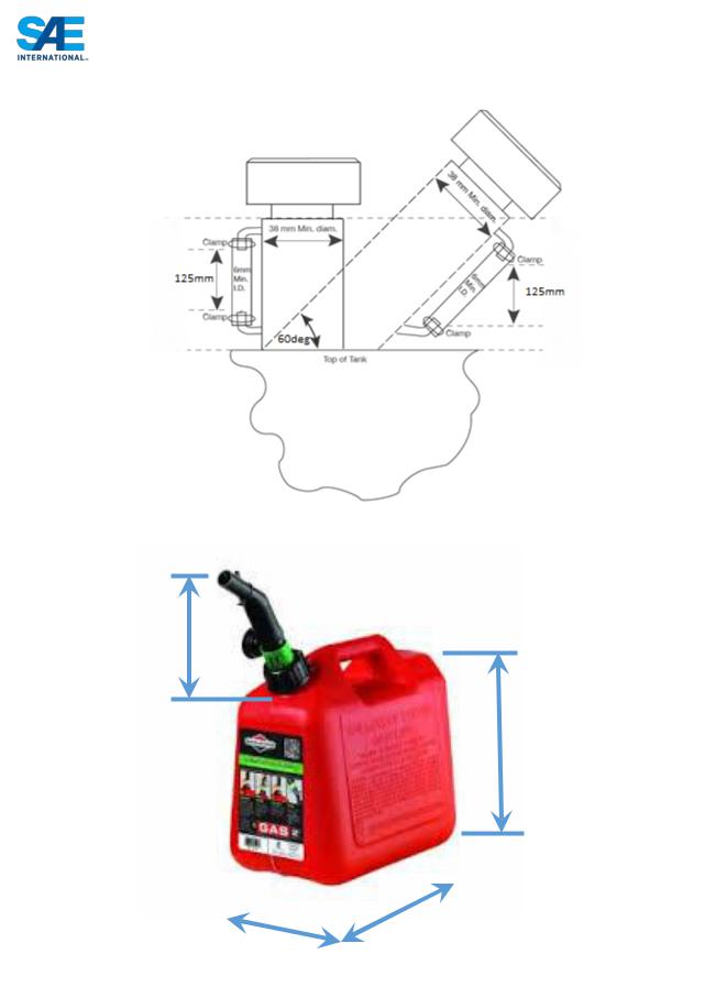
FIGURE 14
250mm Min
350mm Min
|
|
|
|
|
|
|
|
|
|
|
|
250mm Min |
|
250mm Min |
|
|
|
|
|
|
|
|
|
FIGURE 14A – not to scale
|
96 |
© 2015 SAE International. All Rights Reserved |
2016 Formula SAE® Rules – May 11, 2015 |

IC2.6.3 The sight tube must have at least 125 mm (4.9 inches) of visible vertical height and a minimum inside diameter of 6 mm (0.25 inches).
IC2.6.4 The sight tube must not run below the top surface of the fuel tank.
IC2.6.5 A clear filler neck tube may be used as a sight tube, subject to approval by the Rules Committee or technical inspectors at the event.
IC2.6.6 Fuel Level Line - A permanent, non-moveable fuel level line must be located between 12.7 mm and 25.4 mm (0.5 inch and 1 inch) below the top of the visible portion of the sight tube. This line will be used as the fill line for the Tilt Test (Rule T8.5), and before and after the Endurance Test to measure the amount of fuel used during the Endurance Event.
IC2.6.7 The sight tube and fuel level line must be clearly visible to two individuals (one to fill the tank, the other to visually verify fill) without the need of assistance (e.g., artificial lighting, magnifiers) or the need to remove any parts (e.g., body panels).
IC2.6.8 The individual filling the tank must be able to have complete direct access to the filler neck opening with a standard 2 gallon gas can assembly. (See Figure 14A for standard can dimension).
IC2.6.9 The fill neck must have a fuel cap that can withstand severe vibrations or high pressures such as could occur during a vehicle rollover event
IC2.7 Tank Filling Requirement
IC2.7.1 The fuel tank must be capable of being filled to capacity without manipulating the tank or the vehicle in any manner. The Fuel System must be designed in a way that during refueling of the car on a level surface, the formation of air cavities or other effects that cause the fuel level observed at the sight tube to drop after movement or operation of the car (other than due to consumption) is prevented. During fueling or refueling the vehicle may only be touched by the fuel crew and officials. The tank will be filled to the fill line, or if a filling system is used, to the automatic stop point. If, for any reason, the fuel level changes after the team have moved the vehicle, then no additional fuel will be added.
IC2.7.2 The fuel system must be designed such that the spillage during refueling cannot contact the driver position, exhaust system, hot engine parts, or the ignition system.
IC2.7.3 Belly pans must be vented to prevent accumulation of fuel. At least 2 holes, each of a minimum diameter of 25 mm, must be provided in the lowest part of the structure in such a way as to prevent accumulation of volatile liquids and/or vapours.
IC2.8 Venting Systems
IC2.8.1 The fuel tank and carburetor venting systems must be designed such that fuel cannot spill during hard cornering or acceleration. This is a concern since motorcycle carburetors normally are not designed for lateral accelerations.
IC2.8.2 All fuel vent lines must be equipped with a check valve to prevent fuel leakage when the tank is inverted. All fuel vent lines must exit outside the bodywork.
|
97 |
© 2015 SAE International. All Rights Reserved |
2016 Formula SAE® Rules – May 11, 2015 |

ARTICLE 3: EXHAUST SYSTEM AND NOISE CONTROL
IC3.1 Exhaust System General
IC3.1.1 Exhaust Outlet
The exhaust must be routed so that the driver is not subjected to fumes at any speed considering the draft of the car.
IC3.1.2 The exhaust outlet(s) must not extend more than 45 cm (17.7 inches) behind the centerline of the rear axle, and shall be no more than 60 cm (23.6 inches) above the ground.
IC3.1.3 Any exhaust components (headers, mufflers, etc.) that protrude from the side of the body in front of the main roll hoop must be shielded to prevent contact by persons approaching the car or a driver exiting the car.
IC3.1.4 The application of fibrous/absorbent material, e.g. “headerwrap”, to the outside of an exhaust manifold or exhaust system is prohibited.
IC3.2 Noise Measuring Procedure
IC3.2.1 The sound level will be measured during a static test. Measurements will be made with a free-field microphone placed free from obstructions at the exhaust outlet level, 0.5 m (19.68 inches) from the end of the exhaust outlet, at an angle of forty-five degrees (45°) with the outlet in the horizontal plane. The test will be run with the gearbox in neutral at the engine speed defined below. Where more than one exhaust outlet is present, the test will be repeated for each exhaust and the highest reading will be used.
IC3.2.2 The car must be compliant at all engine speeds up to the maximum test speed defined below.
IC3.2.3 If the exhaust has any form of movable tuning or throttling device or system, it must be compliant with the device or system in all positions. The position of the device must be visible to the officials for the noise test and must be manually operable by the officials during the noise test.
IC3.2.4 Test Speeds
The maximum test speed for a given engine will be the engine speed that corresponds to an average piston speed of 914.4 m/min (3,000 ft. /min) for automotive or motorcycle engines, and 731.5 m/min (2,400 ft. /min) for “industrial engines”. The calculated speed will be rounded to the nearest 500 rpm.
The test speeds for typical engines will be published by the organizers.
The idle test speed for a given engine will be up to the team and determined by their calibrated idle speed. If the idle speed varies then the car will be tested across the range of idle speeds determined by the team.
An “industrial engine” is defined as an engine which, according to the manufacturers’ specifications and without the required restrictor, is not capable of producing more than 5 hp per 100cc. To have an engine classified as “an industrial engine”, approval must be obtained from organizers prior to the Competition.
IC3.3 Maximum Sound Level
At idle the maximum permitted sound level is 100 dBC, fast weighting. At all other speeds the maximum permitted sound level is 110 dBC, fast weighting.
|
98 |
© 2015 SAE International. All Rights Reserved |
2016 Formula SAE® Rules – May 11, 2015 |
IC3.4 Noise Level Re-testing
At the option of the officials, noise can be measured at any time during the competition. If a car fails the noise test, it will be withheld from the competition until it has been modified and re-passes the noise test.
ARTICLE 4: ELECTRICAL SYSTEM AND SHUTDOWN SYSTEM
IC4.1 Master Switches
IC4.1.1 The vehicle must be equipped with two (2) master switches which form part of the shutdown system. Actuating either switch must stop the engine.
IC4.1.2 The international electrical symbol consisting of a red spark on a white-edged blue triangle must be affixed in close proximity to each switch.
NOTE: Teams are reminded that any alternator field wire must also be disabled by each master switch to prevent any possible feedback through the field coil circuit.
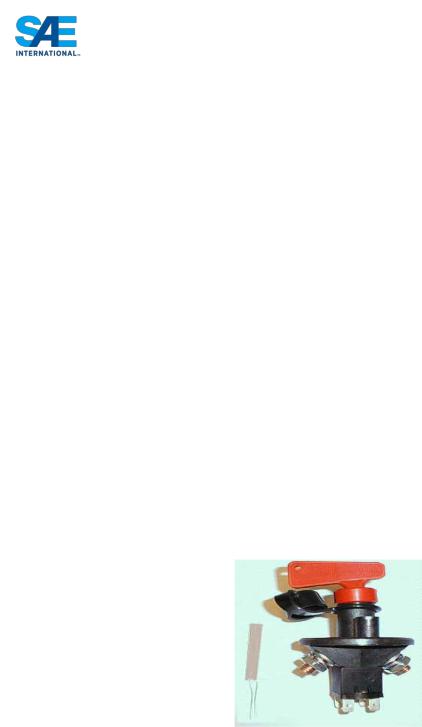
IC4.2 Primary Master Switch
IC4.2.1 The primary master switch must:
a.Be located on the (driver’s) right side of the vehicle, in proximity to the Main Hoop, at shoulder height and be easily actuated from outside the car.
b.Disable power to ALL electrical circuits, including the battery, alternator, lights, fuel pump(s), ignition and electrical controls.
c.All battery current must flow through this switch.
d.Be of a rotary type and must be direct acting, i.e. it cannot act through a relay.
An example of a typical switch that meets these requirements is shown below.
IC4.2.2 The master switches must be mounted so that the rotary axis of the key is near horizontal and across the car. The “ON” position of the switch must be in the horizontal position and must be marked accordingly. The “OFF” position of the primary master switch must also be clearly marked.
IC4.3 Cockpit-mounted Master Switch
IC4.3.1 The cockpit-mounted master switch:
a.Must be located to provide easy actuation by the driver in an emergency or panic situation.
b.Must be located within easy reach of the belted-in driver, alongside the steering wheel, and unobstructed by the steering wheel or any other part of the car. It is suggested that it be placed on the same side of the steering wheel as the shifter mechanism.
|
99 |
© 2015 SAE International. All Rights Reserved |
2016 Formula SAE® Rules – May 11, 2015 |
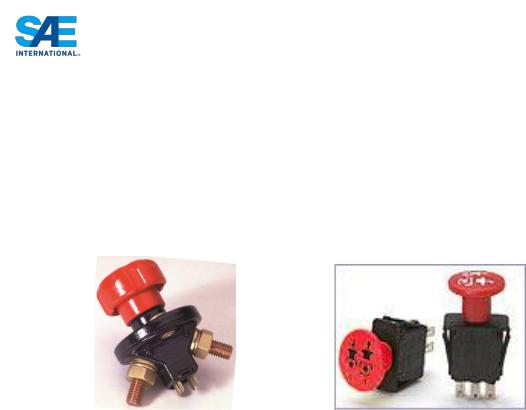
c.Must be a push/pull Emergency switch with a minimum diameter of 24 mm. The switch must be installed such that:
i.From the ON position, pushing on the switch will disable power to the ignition and all fuel pumps, and
ii.From the OFF position, pulling on the switch will enable power to the ignition and fuel pump(s). Switches that require a twist or twist and pull to enable power are acceptable.
d.May act through a relay.
Examples of typical switches that meet these requirements are shown below.
IC4.4 Batteries
IC4.4.1 All batteries, i.e. on-board power supplies, must be attached securely to the frame.
IC4.4.2 Any wet-cell battery located in the driver compartment must be enclosed in a nonconductive marinetype container or equivalent.
IC4.4.3 The hot (ungrounded) terminal must be insulated.
IC4.4.4 Battery packs based on Lithium Chemistry:
a.Must have overcurrent protection that trips at or below the maximum specified discharge current of the cells.
b.Must have a rigid, sturdy and fire retardant casing.
c.Must be separated from the driver by a firewall as specified in T4.5
IC4.4.5 All batteries using chemistries other than lead acid must be presented at technical inspection with markings identifying it for comparison to a datasheet or other documentation proving the pack and supporting electronics meet all rules requirements
IC4.5 Brake-Over-Travel-Switch
The Brake-Over-Travel-Switch forms part of the shutdown system and as defined in T7.3 must remove power from the engine and fuel pumps.
IC4.6 Voltage limit for IC vehicles
The maximum permitted voltage between any two electrical connections is 60V DC or 25V AC RMS.
The following systems are excluded from this voltage limit:
a.High voltage systems for ignition
b.High voltage systems for injectors
c.Voltages internal to OEM charging systems designed for <60VDC output.
|
100 |
© 2015 SAE International. All Rights Reserved |
2016 Formula SAE® Rules – May 11, 2015 |