

2016_FSAE_Rules
.pdfAPPENDIX A – SAE TECHNICAL STANDARDS
The SAE Technical Standards Board (TSB) has made the following SAE Technical Standards available on line, at no cost, for use by Collegiate Design teams. Standards are important in all areas of engineering and we urge you to review these documents and to become familiar will their contents and use.
The technical documents listed below include both (1) standards that are identified in the rules and (2) standards that the TSB and the various rules committees believe are valuable references or which may be mentioned in future rule sets.
All Collegiate Design Series teams registered for competitions in North America have access to all the standards listed below - including standards not specific to your competition.
See FSAE Rule A3.11 “Technical Standards Access” for the access procedure.
SAE Technical Standards included in the CDS Rules
Baja SAE
J586 - Stop Lamps for Use on Motor Vehicles Less Than 2032 mm in Overall Width J759 - Lighting Identification Code
J994 - Alarm - Backup – Electric Laboratory Tests
J1741 - Discriminating Back-Up Alarm Standard
Clean Snowmobile Challenge
J192 - Maximum Exterior Sound Level for Snowmobiles
J1161 - Sound Measurement – Off-Road Self-Propelled Work Machines Operator-Work Cycle
Formula SAE Hybrid
J1318 - Gaseous Discharge Warning Lamp for Authorized Emergency, Maintenance and Service Vehicles J1673 - High Voltage Automotive Wiring Assembly Design
Formula SAE
SAE 4130 steel is referenced but no specific standard is identified
SAE Grade 5 bolts are required but no specific standard is identified
Supermileage
J586 - Stop Lamps for Use on Motor Vehicles Less Than 2032 mm in Overall Width
Electric Standards
SAE Technical Standards for Supplemental Use
Standards Relevant to Baja SAE
J98 – Personal Protection for General Purpose Industrial Machines – Standard J183 – Engine Oil Performance and Engine Service Classification - Standard J306 – Automotive Gear Lubricant Viscosity Classification - Standard
J429 – Mechanical and Material Requirements for Externally Threaded Fasteners – Standard J512 – Automotive Tube Fittings - Standard
J517 – Hydraulic Hose - Standard
J1166 – Sound Measurement – Off-Road Self-Propelled Work Machines Operator-Work Cycle
|
21 |
© 2015 SAE International. All Rights Reserved |
2016 Formula SAE® Rules – May 11, 2015 |

J1194 – Rollover Protective Structures (ROPS) for Wheeled Agricultural Tractors
J1362 – Graphical Symbols for Operator Controls and Displays on Off-Road Self-Propelled Work Machines - Standard
J1614 – Wiring Distribution Systems for Construction, Agricultural and Off-Road Work Machines J1703 - Motor Vehicle Brake Fluid - Standard
J2030 – Heavy Duty Electrical Connector Performance Standard
J2402 – Road Vehicles – Symbols for Controls, Indicators and Tell-Tales – Standard
Standards Relevant to Clean Snowmobile Challenge
J44 – Service Brake System Performance Requirements – Snowmobiles - Recommended Practice J45 – Brake System Test Procedure – Snowmobiles – Recommended Practice
J68 – Tests for Snowmobile Switching Devices and Components - Recommended Practice
J89 – Dynamic Cushioning Performance Criteria for Snowmobile Seats - Recommended Practice J92 – Snowmobile Throttle Control Systems – Recommended Practice
J192 – Maximum Exterior Sound Level for Snowmobiles - Recommended Practice J288 – Snowmobile Fuel Tanks - Recommended Practice
J1161 – Operational Sound Level Measurement Procedure for Snowmobiles - Recommended Practice J1222 – Speed Control Assurance for Snowmobiles - Recommended Practice
J1279 – Snowmobile Drive Mechanisms - Recommended Practice
J1282 – Snowmobile Brake Control Systems - Recommended Practice
J2567 – Measurement of Exhaust Sound Levels of Stationary Snowmobiles - Recommended Practice
Standards Relevant to Formula SAE
J183 – Engine Oil Performance and Engine Service Classification - Standard J306 – Automotive Gear Lubricant Viscosity Classification - Standard
J429 – Mechanical and Material Requirements for Externally Threaded Fasteners – Standard J452 - General Information – Chemical Compositions, Mechanical and Physical Properties of SAE Aluminum Casting Alloys – Information Report
J512 – Automotive Tube Fittings - Standard
J517 – Hydraulic Hose - Standard
J637 – Automotive V-Belt Drives – Recommended Practice J829 – Fuel Tank Filler Cap and Cap Retainer
J1153 - Hydraulic Cylinders for Motor Vehicle Brakes – Test Procedure
J1154 – Hydraulic Master Cylinders for Motor Vehicle Brakes - Performance Requirements - Standard J1703 - Motor Vehicle Brake Fluid - Standard
J2045 – Performance Requirements for Fuel System Tubing Assemblies - Standard J2053 – Brake Master Cylinder Plastic Reservoir Assembly for Road Vehicles – Standard
Standard Relevant to Formula Hybrid
J1772 – SAE Electric Vehicle and Plug in Hybrid Conductive Charge Coupler
Standard Relevant to all CDS Competitions
J1739 – Potential Failure Mode and Effects Analysis in Design (Design FMEA) Potential Failure Mode and Effects Analysis in Manufacturing and Assembly Processes (Process FMEA) and Potential Failure Mode and Effects Analysis for Machinery (Machinery FMEA)
|
22 |
© 2015 SAE International. All Rights Reserved |
2016 Formula SAE® Rules – May 11, 2015 |

2016 FORMULA SAE RULES
PART T - GENERAL TECHNICAL REQUIREMENTS
ARTICLE 1: VEHICLE REQUIREMENTS & RESTRICTIONS T1.1 Technical Inspection
The following requirements and restrictions will be enforced through technical inspection. Noncompliance must be corrected and the car re-inspected before the car is allowed to operate under power.
T1.2 Modifications and Repairs
T1.2.1 Once the vehicle has been presented for judging in the Cost or Design Events, or submitted for Technical Inspection, and until the vehicle is approved to compete in the dynamic events, i.e. all the inspection stickers are awarded, the only modifications permitted to the vehicle are those directed by the Inspector(s) and noted on the Inspection Form.
T1.2.2 Once the vehicle is approved to compete in the dynamic events, the ONLY modifications permitted to the vehicle are those listed below. They are also referred to in PART S - Static Event Regulations.
a.Adjustment of belts, chains and clutches
b.Adjustment of brake bias
c.Adjustment of the driver restraint system, head restraint, seat and pedal assembly
d.Substitution of the head restraint or seat insert for different drivers
e.Adjustment to engine operating parameters, e.g. fuel mixture and ignition timing, and any software calibration changes
f.Adjustment of mirrors
g.Adjustment of the suspension where no part substitution is required, (except that springs, sway bars and shims may be changed)
h.Adjustment of tire pressure
i.Adjustment of wing angle, but not the location
j.Replenishment of fluids
k.Replacement of worn tires or brake pads. Replacement tires and brake pads must be identical in material/composition/size to those presented and approved at Technical Inspection.
l.The changing of wheels and tires for “wet” or “damp” conditions as allowed in PART D - Dynamic Event Regulations.
m.Recharging low voltage batteries
n.Recharging high voltage accumulators
T1.2.3 The vehicle must maintain all required specifications, e.g. ride height, suspension travel, braking capacity (pad material/composition), sound level and wing location throughout the competition.
T1.2.4 Once the vehicle is approved for competition, any damage to the vehicle that requires repair, e.g. crash damage, electrical or mechanical damage will void the Inspection Approval. Upon the completion of the repair and before re-entering into any dynamic competition, the vehicle MUST be re-submitted to Technical Inspection for re-approval.
|
23 |
© 2015 SAE International. All Rights Reserved |
2016 Formula SAE® Rules – May 11, 2015 |
ARTICLE 2: GENERAL DESIGN REQUIREMENTS T2.1 Vehicle Configuration
The vehicle must be open-wheeled and open-cockpit (a formula style body) with four (4) wheels that are not in a straight line.
Definition of "Open Wheel" – Open Wheel vehicles must satisfy all of the following criteria:
a.The top 180 degrees of the wheels/tires must be unobstructed when viewed from vertically above the wheel.
b.The wheels/tires must be unobstructed when viewed from the side.
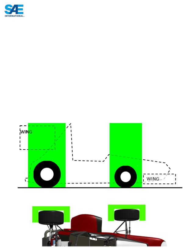
c.No part of the vehicle may enter a keep-out-zone defined by two lines extending vertically from positions 75mm in front of and 75mm behind, the outer diameter of the front and rear tires in the side view elevation of the vehicle, with tires steered straight ahead. This keepout zone will extend laterally from the outside plane of the wheel/tire to the inboard plane of the wheel/tire. See the figure “Keep Out Zones” below.
d.Must also comply with the dimensions/requirements of ARTICLE 9: Aerodynamic Devices.
NOTE: The dry tires will be used for all inspections.
T2.2 |
Bodywork |
|
|
There must be no openings through the bodywork into the driver compartment from the front of the |
|
|
vehicle back to the roll bar main hoop or firewall other than that required for the cockpit opening. |
|
|
Minimal openings around the front suspension components are allowed. |
|
|
|
24 |
|
© 2015 SAE International. All Rights Reserved |
2016 Formula SAE® Rules – May 11, 2015 |

T2.3 Wheelbase
The car must have a wheelbase of at least 1525 mm (60 inches). The wheelbase is measured from the center of ground contact of the front and rear tires with the wheels pointed straight ahead.
T2.4 Vehicle Track
The smaller track of the vehicle (front or rear) must be no less than 75% of the larger track.
T2.5 Visible Access
All items on the Inspection Form must be clearly visible to the technical inspectors without using instruments such as endoscopes or mirrors. Visible access can be provided by removing body panels or by providing removable access panels.
ARTICLE 3: DRIVER’S CELL
T3.1 Vehicle Structure - 2 Options
Teams may, at their option, design their vehicle to comply with either of two (2) separate, but related, sets of requirements and restrictions. Specifically, teams may elect to comply with either:
a.Part T Article 3 “Drivers Cell” as defined below or
b.Part AF “Alternate Frame Rules” as found in Appendix AF and the FSAE website.
T3.1.1 |
Notice Requirement – Teams planning to use the Part AF “Alternate Frame Rules” must notify the |
||
|
Rules Committee of their intent by the date posted on the SAE Website. The instructions for |
||
|
notification appear in Part AF. The Rules Committee will review the submission and notify the team |
||
|
if the request is granted. Part AF has significant analytical requirements and as it is still in |
||
|
development this application process will insure that the Committee can handle the workload and give |
||
|
teams the support they may require to show certification as well as insure the teams have the technical |
||
|
capability to analyze their design and prove compliance with the AF Rules. |
||
T3.1.2 |
Alternate Frame Rules use requires the submission of the “Structural Requirements Certification Form |
||
|
(SRCF)” which supersedes the “Structural Equivalency Spreadsheet”. |
||
|
Teams submitting a Structural Requirements Certification Form (SRCF) do not have to submit a |
||
|
Structural Equivalency Spreadsheet (SES). |
|
|
T3.2 |
General Requirements |
|
|
|
Among other requirements, the vehicle’s structure must include two roll hoops that are braced, a front |
||
|
bulkhead with support system and Impact Attenuator, and side impact structures. |
||
T3.3 |
Definitions |
|
|
|
The following definitions apply throughout the Rules document: |
||
|
a. |
Main Hoop - A roll bar located alongside or just behind the driver’s torso. |
|
|
b. |
Front Hoop - A roll bar located above the driver’s legs, in proximity to the steering wheel. |
|
|
c. |
Roll Hoops – Both the Front Hoop and the Main Hoop are classified as “Roll Hoops” |
|
|
d. |
Roll Hoop Bracing Supports – The structure from the lower end of the Roll Hoop Bracing back to |
|
|
|
the Roll Hoop(s). |
|
|
e. |
Frame Member - A minimum representative single piece of uncut, continuous tubing. |
|
|
f. |
Frame - The “Frame” is the fabricated structural assembly that supports all functional vehicle |
|
|
|
systems. This assembly may be a single welded structure, multiple welded structures or a |
|
|
|
combination of composite and welded structures. |
|
|
g. |
Primary Structure – The Primary Structure is comprised of the following Frame components: |
|
|
|
25 |
|
© 2015 SAE International. All Rights Reserved |
2016 Formula SAE® Rules – May 11, 2015 |
||

i.Main Hoop,
ii.Front Hoop,
iii.Roll Hoop Braces and Supports,
iv.Side Impact Structure,
v.Front Bulkhead,
vi.Front Bulkhead Support System and
vii.All Frame Members, guides and supports that transfer load from the Driver’s Restraint
System into items 1 through 6.
h.Major Structure of the Frame – The portion of the Frame that lies within the envelope defined by the Primary Structure. The upper portion of the Main Hoop and the Main Hoop Bracing are not included in defining this envelope.
i.Front Bulkhead – A planar structure that defines the forward plane of the Major Structure of the
Frame and functions to provide protection for the driver’s feet.
j.Impact Attenuator – A deformable, energy absorbing device located forward of the Front Bulkhead.
k.Side Impact Zone – The area of the side of the car extending from the top of the floor to 350 mm (13.8 inches) above the ground and from the Front Hoop back to the Main Hoop.
l.Node-to-node triangulation – An arrangement of frame members projected onto a plane, where a co-planar load applied in any direction, at any node, results in only tensile or compressive forces in the frame members. This is also what is meant by “properly triangulated”.
|
|
|
|
|
|
|
|
|
|
|
|
|
|
|
|
|
|
|
|
|
|
|
|
|
|
Not OK |
|
|
Properly Triangulated |
||
T3.4 Minimum Material Requirements
T3.4.1 Baseline Steel Material
The Primary Structure of the car must be constructed of:
Either: Round, mild or alloy, steel tubing (minimum 0.1% carbon) of the minimum dimensions specified in the following table,
Or: Approved alternatives per Rules T3.5, T3.6 and T3.7.
|
ITEM or APPLICATION |
OUTSIDE DIMENSION |
|
|
X WALL THICKNESS |
|
|
|
|
Main & Front Hoops, |
Round 1.0 inch (25.4 mm) x 0.095 inch (2.4 mm) |
|
|
|
|
Shoulder Harness Mounting Bar |
or Round 25.0 mm x 2.50 mm metric |
|
|
|
|
|
|
|
Side Impact Structure, Front Bulkhead, |
Round 1.0 inch (25.4 mm) x 0.065 inch (1.65 mm) |
|
Roll Hoop Bracing, |
or Round 25.0 mm x 1.75 mm metric |
|
Driver’s Restraint Harness Attachment |
or Round 25.4 mm x 1.60 mm metric |
|
(except as noted above) |
or Square 1.00 inch x 1.00 inch x 0.047 inch |
|
|
26 |
© 2015 SAE International. All Rights Reserved |
2016 Formula SAE® Rules – May 11, 2015 |
|

EV: Accumulator Protection Structure |
or Square 25.0 mm x 25.0 mm x 1.20 mm metric |
|
|
Front Bulkhead Support, Main Hoop |
Round 1.0 inch (25.4 mm) x 0.047 inch (1.20 mm) |
Bracing Supports |
or Round 25.0 mm x 1.5 mm metric |
EV: Tractive System Components |
or Round 26.0 mm x 1.2 mm metric |
|
|
NOTE 1: The use of alloy steel does not allow the wall thickness to be thinner than that used for mild steel.
NOTE 2: For a specific application:
-Using tubing of the specified outside diameter but with greater wall thickness,
-Or of the specified wall thickness and a greater outside diameter,
-Or replacing round tubing with square tubing of the same or larger size to those listed above, are NOT rules deviation requiring approval.
NOTE 3: Except for inspection holes, any holes drilled in any regulated tubing require the submission of an SES.
NOTE 4: Baseline steel properties used for calculations to be submitted in an SES may not be lower than the following:
Bending and buckling strength calculations:
Young’s Modulus (E) = 200 GPa (29,000 ksi)
Yield Strength (Sy) = 305 MPa (44.2 ksi)
Ultimate Strength (Su) = 365 MPa (52.9 ksi)
Welded monocoque attachment points or welded tube joint calculations:
Yield Strength (Sy) = 180 MPa (26ksi)
Ultimate Strength (Su) = 300 MPa (43.5 ksi)
Where welded tubing reinforcements are required (e.g. inserts for bolt holes or material to support suspension cutouts) the tubing must retain the baseline cold rolled strength while using the welded strength for the additional reinforcement material.
NOTE 5: Any tubing smaller than 1”x0.047” (or an approved alternative as per Rules T3.5, T3.6 or T3.7) is not considered structural and will be ignored when assessing compliance to any rule listed within Part T.
T3.5 Alternative Tubing and Material - General
T3.5.1 Alternative tubing geometry and/or materials may be used except that the Main Roll Hoop and Main Roll Hoop Bracing must be made from steel, i.e. the use of aluminum or titanium tubing or composites for these components is prohibited.
T3.5.2 Titanium or magnesium on which welding has been utilized may not be used for any part of the Primary Structure. This includes the attachment of brackets to the tubing or the attachment of the tubing to other components.
T3.5.3 If a team chooses to use alternative tubing and/or materials they must submit a “Structural Equivalency Spreadsheet” per Rule T3.9. The teams must submit calculations for the material they have chosen, demonstrating equivalence to the minimum requirements found in Section T3.4.1 for
|
27 |
© 2015 SAE International. All Rights Reserved |
2016 Formula SAE® Rules – May 11, 2015 |

yield and ultimate strengths in bending, buckling and tension, for buckling modulus and for energy dissipation. (The Buckling Modulus is defined as EI, where, E = modulus of Elasticity, and I = area moment of inertia about the weakest axis.)
T3.5.4 Tubing cannot be of thinner wall thickness than listed in T3.6 or T3.7.
T3.5.5 If a bent tube(or member consisting of multiple tubes that are not in a line) is used anywhere in the primary structure, other than the front and main roll hoops, an additional tube must be attached to support it. The attachment point must be the position along the tube where it deviates farthest from a straight line connecting both ends. The support tube must have the same diameter and thickness as the bent tube, terminate at a node of the chassis, and be angled no more than 45 degrees from the plane of the bent tube. Braces attached to the upper side impact member are not required to meet the 45 degree from the plane of the bent tube requirement.
T3.5.6 Any chassis design that is a hybrid of the baseline and monocoque rules, must meet all relevant rules requirements, e.g. a sandwich panel side impact structure in a tube frame chassis must meet the requirements of rules T3.27, T3.28, T3.29, T3.30 and T3.33.
NOTE: It is allowable for the properties of tubes and laminates to be combined to prove equivalence. E.g. n a side-impact structure consisting of one tube as per T3.4 and a laminate panel, the panel only needs to be equivalent to two side-impact tubes.
T3.6 |
Alternative Steel Tubing |
|
|
Minimum Wall Thickness Allowed |
|
|
MATERIAL & APPLICATION |
MINIMUM WALL |
|
|
THICKNESS |
|
|
|
|
Steel Tubing for Front and Main Roll Hoops, |
|
|
and Shoulder Harness Mounting Bar |
2.0 mm (0.079 inch) |
|
Steel Tubing for Roll Hoop Bracing, Roll Hoop Bracing |
|
|
Supports, Side Impact Structure, Front Bulkhead, |
1.2 mm (0.047 inch) |
|
Front Bulkhead Support, Driver’s Harness Attachment (except as |
|
|
noted above), Protection of HV accumulators, and protection of |
|
|
HV tractive systems |
|
|
|
|
Minimum Wall Thickness Allowed for teams satisfying physical testing requirements:
MATERIAL & APPLICATION |
MINIMUM WALL |
|
THICKNESS |
Steel Tubing for Front and Main Roll Hoops, |
|
and Shoulder Harness Mounting Bar |
1.6 mm (0.065 inch) |
Steel Tubing for Roll Hoop Bracing, Roll Hoop Bracing |
|
Supports, Side Impact Structure, Front Bulkhead, |
0.9 mm (0.035 inch) |
Front Bulkhead Support, Driver’s Harness Attachment (except as |
|
noted above), Protection of HV accumulators, and protection of |
|
HV tractive systems |
|
|
|
NOTE 1: All steel is treated equally - there is no allowance for alloy steel tubing, e.g. SAE 4130, to have a thinner wall thickness than that used with mild steel.
|
28 |
© 2015 SAE International. All Rights Reserved |
2016 Formula SAE® Rules – May 11, 2015 |

NOTE 2: To maintain EI with a thinner wall thickness than specified in T3.4.1, the outside diameter MUST be increased.
NOTE 3: To maintain the equivalent yield and ultimate tensile strength the same cross-sectional area of steel as the baseline tubing specified in T3.4.1 MUST be maintained.
NOTE 4: Teams using the Alternative Frame Rules must comply with rule T3.6.
T3.6.1 Test samples representing the joining method to be used on the Primary Structure must be constructed by team members and pull tested to determine joint strength and quality.
T3.6.2 Test samples must be constructed in an “H” pattern with two parallel 203mm (8 inches) long tubes separated by 38mm (1.5 inches) measured from the tube centerline. The connecting tube must be perpendicular to the parallel tubes and be 50mm (2 inches) from the top end of one tube and 50mm (2 inches) from the bottom end of the other tube.
T3.6.3 Construction of the test samples must meet the following requirements:
a.The test samples must use the same mild/alloy steel as is used in the construction of the chassis.
b.For each alternative configuration that is used in the vehicle design both the alternative and baseline must be tested and compared.
c.Two samples of each joint must be manufactured and tested, two each of the baseline and two each of the alternative joint. NOTE: this means the minimum number of tests is four.
|
Baseline joint |
|
Alternate tube thickness joint |
||
|
inches |
metric |
|
inches |
metric |
|
1"x0.095" to |
25.4mm x 2.4 mm to |
--> |
1"x0.095" to |
25.4mm x 2.4 mm to |
|
1"x0.047" |
25.4mm x 1.2 mm |
1.375"x0.035" |
34.9mm x 0.9 mm |
|
|
|
||||
|
1"x0.063" to |
25.4mm x 1.6 mm to |
--> |
1"x0.063" to |
25.4mm x 1.6 mm to |
|
1"x0.047" |
25.4mm x 1.2 mm |
1.375"x0.035" |
34.9mm x 0.9 mm |
|
|
|
||||
|
1"x0.047" to |
25.4mm x 1.2 mm to |
--> |
1"x0.047" to |
25.4mm x 1.2 mm to |
|
1"x0.047" |
25.4mm x 1.2 mm |
1.375"x0.035" |
34.9mm x 0.9 mm |
|
|
|
||||
|
1"x0.047" to |
25.4mm x 1.2 mm to |
--> |
1.375"x0.035" to |
34.9mm x 0.9 mm to |
|
1"x0.047" |
25.4mm x 1.2 mm |
1.375x0.035" |
34.9mm x 0.9 mm |
|
|
|
||||
|
|
|
29 |
|
|
© 2015 SAE International. All Rights Reserved |
|
2016 Formula SAE® Rules – May 11, 2015 |
|||

d.The thinnest wall thickness tube must be the short perpendicular tube between the parallel tubes.
e.Teams may modify or add material at the ends of the test samples for mounting into a pull test machine. Mounting end modifications must be consistent across all test samples.
f.Any post welding heat treatment such as annealing must be consistent across all test samples and with the actual vehicle frame. Altering the shape of the weld is not allowed (no grinding or sanding).
T3.6.4 Test samples must be pull tested to failure. Force vs. Deflection curves for all samples must be submitted for review in the SES. The “physical test requirement” is satisfied if the minimum failure load for both "Alternate tube thickness" test samples is within 95 percent of the minimum failure load of either corresponding "Baseline joint" test sample. Test results must be documented in the SES or SRCF and test samples must be available to technical inspectors at competition
T3.7 Aluminum Tubing Requirements
T3.7.1 Minimum Wall Thickness: Aluminum Tubing 3.0 mm (0.118 inch)
T3.7.2 The equivalent yield strength must be considered in the “as-welded” condition, (Reference:
WELDING ALUMINUM (latest Edition) by the Aluminum Association, or THE WELDING HANDBOOK, Volume 4, 7th Ed., by The American Welding Society), unless the team demonstrates and shows proof that the frame has been properly solution heat treated and artificially aged.
T3.7.3 Should aluminum tubing be solution heat-treated and age hardened to increase its strength after welding; the team must supply sufficient documentation as to how the process was performed. This includes, but is not limited to, the heat-treating facility used, the process applied, and the fixturing used.
T3.8 Composite Materials
T3.8.1 If any composite or other material is used, the team must present documentation of material type, e.g. purchase receipt, shipping document or letter of donation, and of the material properties. Details of the composite lay-up technique as well as the structural material used (cloth type, weight, and resin type, number of layers, core material, and skin material if metal) must also be submitted. The team must submit calculations demonstrating equivalence of their composite structure to one of similar geometry made to the minimum requirements found in Section T3.4.1. Equivalency calculations must be submitted for energy dissipation, yield and ultimate strengths in bending, buckling, and tension.
Submit the completed “Structural Equivalency Spreadsheet” per Section T3.9.
T3.8.2 Composite materials are not allowed for the Main Hoop or the Front Hoop.
T3.9 Structural Documentation – SES or SRCF Submission
All equivalency calculations must prove equivalency relative to steel grade SAE/AISI 1010.
T3.9.1 All teams MUST submit either a STRUCTURAL EQUIVALENCY SPREADSHEET (SES) or a STRUCTURAL REQUIREMENTS CERTIFICATION FORM (SCRF).
Teams complying with the Part T Article 3 “Drivers Cell” rules MUST submit a Structural
Equivalence Spreadsheet (SES), even if they are NOT planning to use alternative materials or tubing sizes to those specified in T3.4.1 Baseline Steel Materials.
|
30 |
© 2015 SAE International. All Rights Reserved |
2016 Formula SAE® Rules – May 11, 2015 |