

2016_FSAE_Rules
.pdfTeams following the Part AF “Alternate Frame Rules” MUST submit a Structural Requirements
Certification Form (SRCF). See Rule Part AF - AF2.1.
T3.9.2 The use of alternative materials or tubing sizes to those specified in T3.4.1 “Baseline Steel Material,” is allowed, provided they have been judged by a technical review to have equal or superior properties to those specified in T3.4.1.
T3.9.3 Approval of alternative material or tubing sizes will be based upon the engineering judgment and experience of the chief technical inspector or his appointee.
T3.9.4 The technical review is initiated by completing the “Structural Equivalency Spreadsheet” (SES) using the format given in Appendix T-1.
T3.9.5 Structural Equivalency Spreadsheet – Submission
a.Address – SESs must be submitted to the officials at the competition you are entering at the address shown in the Appendix or indicated on the competition website.
b.Due Date – SESs must be submitted no later than the date indicated on the competition website. Teams that submit their Structural Equivalency Spreadsheet after the due date for the competition will be penalized 10 points per day up to a maximum of 50 points, which will be taken off the team’s Total Score.
c.Acknowledgement – North America competitions – SESs submitted for vehicles entered into competitions held in North America will be acknowledged automatically by the fsaeonline website.
Do Not Resubmit SES’s unless instructed to do so.
T3.9.6 Vehicles completed under an approved SES must be fabricated in accordance with the materials and processes described in the SES.
T3.9.7 Teams must bring a copy of the approved SES with them to Technical Inspection.
Comment - The resubmission of an SES that was written and submitted for a competition in a previous year is strongly discouraged. Each team is expected to perform their own tests and to submit SESs based on their original work. Understanding the engineering that justifies the equivalency is essential to discussing your work with the officials.
T3.10 Main and Front Roll Hoops – General Requirements
T3.10.1 The driver’s head and hands must not contact the ground in any rollover attitude.
T3.10.2 The Frame must include both a Main Hoop and a Front Hoop as shown in Figure 1.
T3.10.3 When seated normally and restrained by the Driver’s Restraint System, the helmet of a 95th percentile male (anthropometrical data) and all of the team’s drivers must:
a.Be a minimum of 50.8 mm (2 inches) from the straight line drawn from the top of the main hoop to the top of the front hoop. (Figure 1a)
b.Be a minimum of 50.8 mm (2 inches) from the straight line drawn from the top of the main hoop to the lower end of the main hoop bracing if the bracing extends rearwards. (Figure 1b)
c.Be no further rearwards than the rear surface of the main hoop if the main hoop bracing extends forwards. (Figure 1c)
|
31 |
© 2015 SAE International. All Rights Reserved |
2016 Formula SAE® Rules – May 11, 2015 |

95th Percentile Male Template Dimensions
A two dimensional template used to represent the 95th percentile male is made to the following dimensions:
A circle of diameter 200 mm (7.87 inch) will represent the hips and buttocks.
A circle of diameter 200 mm (7.87 inch) will represent the shoulder/cervical region.
A circle of diameter 300 mm (11.81 inch) will represent the head (with helmet).
A straight line measuring 490 mm (19.29 inch) will connect the centers of the two 200 mm circles.
A straight line measuring 280 mm (11.02 inch) will connect the centers of the upper 200 mm circle and the 300 mm head circle.
|
32 |
© 2015 SAE International. All Rights Reserved |
2016 Formula SAE® Rules – May 11, 2015 |
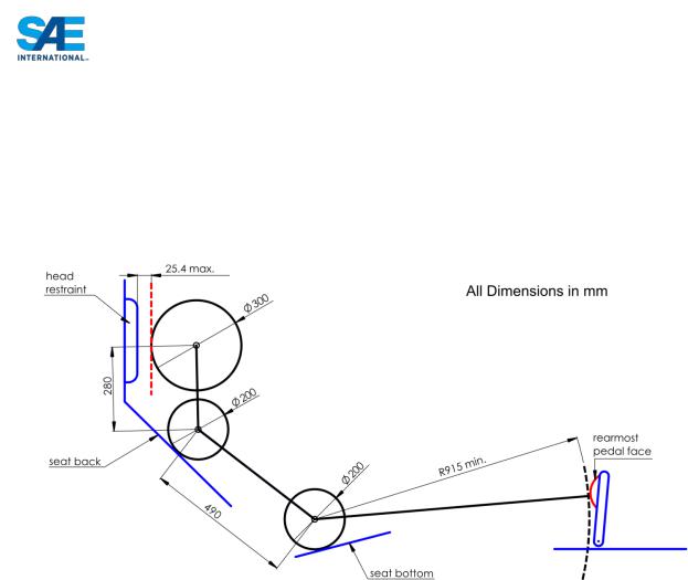
T3.10.4 The 95th percentile male template will be positioned as follows: (See Figure 2.)
a.The seat will be adjusted to the rearmost position,
b.The pedals will be placed in the most forward position.
c.The bottom 200 mm circle will be placed on the seat bottom such that the distance between the center of this circle and the rearmost face of the pedals is no less than 915 mm (36 inches).
d.The middle 200 mm circle, representing the shoulders, will be positioned on the seat back.
e.The upper 300 mm circle will be positioned no more than 25.4 mm (1 inch) away from the head restraint (i.e. where the driver’s helmet would normally be located while driving).
T3.10.5 If the requirements of T3.10.4 are not met with the 95th percentile male template, the car will NOT receive a Technical Inspection Sticker and will not be allowed to compete in the dynamic events.
T3.10.6 Drivers who do not meet the helmet clearance requirements of T3.10.3 will not be allowed to drive in the competition.
T3.10.7 The minimum radius of any bend, measured at the tube centerline, must be at least three times the tube outside diameter. Bends must be smooth and continuous with no evidence of crimping or wall failure.
T3.10.8 The Main Hoop and Front Hoop must be securely integrated into the Primary Structure using proper triangulation.
T3.11 Main Hoop
T3.11.1 The Main Hoop must be constructed of a single piece of uncut, continuous, closed section steel tubing per Rule T3.4.1.
T3.11.2 The use of aluminum alloys, titanium alloys or composite materials for the Main Hoop is prohibited.
T3.11.3 The Main Hoop must extend from the lowest Frame Member on one side of the Frame, up, over and down the lowest Frame Member on the other side of the Frame.
|
33 |
© 2015 SAE International. All Rights Reserved |
2016 Formula SAE® Rules – May 11, 2015 |

T3.11.4 In the side view of the vehicle, the portion of the Main Roll Hoop that lies above its attachment point to the Major Structure of the Frame (the point where it attaches to the upper Side Impact Tube) must be within ten degrees (10°) of the vertical.
T3.11.5 In the side view of the vehicle, any bends in the Main Roll Hoop above its attachment point to the Major Structure of the Frame must be braced to a node of the Main Hoop Bracing Support structure with tubing meeting the requirements of Roll Hoop Bracing as per Rule T3.4.1.
T3.11.6 In the side view of the vehicle, the portion of the Main Roll Hoop that lies below the upper side impact member attachment point may be inclined at any angle to the vertical in the forward direction but, it can only be inclined rearward within ten degrees (10°) of the vertical.
T3.11.7 In the front view of the vehicle, the vertical members of the Main Hoop must be at least 380 mm (15 inch) apart (inside dimension) at the location where the Main Hoop is attached to the bottom tubes of the Major Structure of the Frame.
T3.12 Front Hoop
T3.12.1 The Front Hoop must be constructed of closed section metal tubing per Rule T3.4.1.
T3.12.2 The Front Hoop must extend from the lowest Frame Member on one side of the Frame, up, over and down to the lowest Frame Member on the other side of the Frame.
T3.12.3 With proper triangulation, it is permissible to fabricate the Front Hoop from more than one piece of tubing.
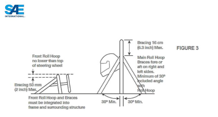
T3.12.4 The top-most surface of the Front Hoop must be no lower than the top of the steering wheel in any angular position.
T3.12.5 The Front Hoop must be no more than 250 mms (9.8 inches) forward of the steering wheel. This distance shall be measured horizontally, on the vehicle centerline, from the rear surface of the Front Hoop to the forward most surface of the steering wheel rim with the steering in the straight-ahead position.
T3.12.6 In side view, no part of the Front Hoop can be inclined at more than twenty degrees (20°) from the vertical.
T3.13 Main Hoop Bracing
T3.13.1 Main Hoop braces must be constructed of closed section steel tubing per Rule T3.4.1.
T3.13.2 The Main Hoop must be supported by two braces extending in the forward or rearward direction on both the left and right sides of the Main Hoop.
T3.13.3 In the side view of the Frame, the Main Hoop and the Main Hoop braces must not lie on the same side of the vertical line through the top of the Main Hoop, i.e. if the Main Hoop leans forward, the braces must be forward of the Main Hoop, and if the Main Hoop leans rearward, the braces must be rearward of the Main Hoop.
T3.13.4 The Main Hoop braces must be attached as near as possible to the top of the Main Hoop but not more than 160 mm (6.3 in) below the top-most surface of the Main Hoop. The included angle formed by the Main Hoop and the Main Hoop braces must be at least thirty degrees (30°). See Figure 3.
|
34 |
© 2015 SAE International. All Rights Reserved |
2016 Formula SAE® Rules – May 11, 2015 |
T3.13.5 The Main Hoop braces must be straight, i.e. without any bends.
T3.13.6 The Main Hoop Braces must be securely integrated into the Frame and be capable of transmitting all loads from the Main Hoop into the Major Structure of the Frame without failing.
T3.13.7 The lower end of the Main Hoop Braces must be supported back to the Main Hoop by a minimum of two Frame Members on each side of the vehicle; an upper member and a lower member in a properly triangulated configuration.
a.The upper support member must attach to the node where the upper Side Impact Member attaches to the Main Hoop.
b.The lower support member must attach to the node where the lower Side Impact Member attaches to the Main Hoop.
NOTE: Each of the above members can be multiple or bent tubes provided the requirements of T3.5.5 are met.
T3.13.8 All the Frame Members of the Main Hoop Bracing Support system listed above must be constructed of closed section tubing per Section T3.4.1.
T3.13.9 If any item which is outside the envelope of the Primary Structure is attached to the Main Hoop braces, then additional bracing must be added to prevent bending loads in the braces in any rollover attitude
T3.14 Front Hoop Bracing
T3.14.1 Front Hoop braces must be constructed of material per Rule T3.4.1.
T3.14.2 The Front Hoop must be supported by two braces extending in the forward direction on both the left and right sides of the Front Hoop.
T3.14.3 The Front Hoop braces must be constructed such that they protect the driver’s legs and should extend to the structure in front of the driver’s feet.
|
35 |
© 2015 SAE International. All Rights Reserved |
2016 Formula SAE® Rules – May 11, 2015 |
T3.14.4 The Front Hoop braces must be attached as near as possible to the top of the Front Hoop but not more than 50.8 mm (2 in) below the top-most surface of the Front Hoop. See Figure 3.
T3.14.5 If the Front Hoop leans rearwards by more than ten degrees (10°) from the vertical, it must be supported by additional bracing to the rear. This bracing must be constructed of material per Rule T3.4.1.
T3.14.6 The driver’s feet and legs must be completely contained within the Major Structure of the Frame. While the driver’s feet are touching the pedals, in side and front views, no part of the driver’s feet or legs can extend above or outside of the Major Structure of the Frame.
T3.15 Other Bracing Requirements
Where the braces are not welded to steel Frame Members, the braces must be securely attached to the Frame using 8 mm Metric Grade 8.8 (5/16 in SAE Grade 5), or stronger, bolts. Mounting plates welded to the Roll Hoop braces must be at least 2.0 mm (0.080 in) thick steel.
T3.16 Other Side Tube Requirements
If there is a Roll Hoop brace or other frame tube alongside the driver, at the height of the neck of any of the team’s drivers, a metal tube or piece of sheet metal must be firmly attached to the Frame to prevent the drivers’ shoulders from passing under the roll hoop brace or frame tube, and his/her neck contacting this brace or tube.
T3.17 Mechanically Attached Roll Hoop Bracing
T3.17.1 Roll Hoop bracing may be mechanically attached.
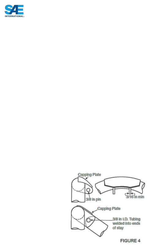
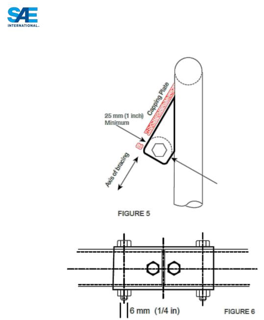
T3.17.2 Any non-permanent joint at either end must be either a double-lug joint as shown in Figures 4 and 5, or a sleeved butt joint as shown in Figure 6.
|
36 |
© 2015 SAE International. All Rights Reserved |
2016 Formula SAE® Rules – May 11, 2015 |
T3.17.3 The threaded fasteners used to secure non-permanent joints are considered critical fasteners and must comply with ARTICLE 11:
T3.17.4 No spherical rod ends are allowed.
T3.17.5 For double-lug joints, each lug must be at least 4.5 mm (0.177 in) thick steel, measure 25 mm (1.0 in) minimum perpendicular to the axis of the bracing and be as short as practical along the axis of the bracing.
T3.17.6 All double-lug joints, whether fitted at the top or bottom of the tube, must include a capping arrangement (Figures 4 & 5).
T3.17.7 In a double-lug joint the pin or bolt must be 10 mm Metric Grade 9.8 (3/8 in. SAE Grade 8) minimum. The attachment holes in the lugs and in the attached bracing must be a close fit with the pin or bolt.
|
37 |
© 2015 SAE International. All Rights Reserved |
2016 Formula SAE® Rules – May 11, 2015 |

T3.17.8 For sleeved butt joints (Figure 6), the sleeve must have a minimum length of 76 mm (3 inch); 38 mm (1.5 inch) either side of the joint, and be a close-fit around the base tubes. The wall thickness of the sleeve must be at least that of the base tubes. The bolts must be 6 mm Metric Grade 9.8 (1/4 inch SAE Grade 8) minimum. The holes in the sleeves and tubes must be a close-fit with the bolts.
T3.18 Bulkhead
T3.18.1 The Front Bulkhead must be constructed of closed section tubing per Rule T3.4.1.
T3.18.2 Except as allowed by T3.18.3, The Front Bulkhead must be located forward of all non-crushable objects, e.g. batteries, master cylinders, hydraulic reservoirs.
T3.18.3 The Front Bulkhead must be located such that the soles of the driver’s feet, when touching but not applying the pedals, are rearward of the bulkhead plane. (This plane is defined by the forward-most surface of the tubing.) Adjustable pedals must be in the forward most position.
T3.19 Front Bulkhead Support
T3.19.1 The Front Bulkhead must be securely integrated into the Frame.
T3.19.2 The Front Bulkhead must be supported back to the Front Roll Hoop by a minimum of three Frame Members on each side of the vehicle; an upper member; lower member and diagonal brace to provide triangulation.
a.The upper support member must be attached within 50mm (2”) of the top surface of the Front Bulkhead, and attach to the Front Roll Hoop within a zone extending 100mm (4”) above and 50mm (2”) below the Upper Side Impact member. If the upper support member is further than 100mm (4”) above the Upper Side Impact member then properly triangulated bracing is required to transfer load to the attachment of the Upper Side Impact member to the Front Roll Hoop.
b.The lower support member must be attached to the base of the Front Bulkhead and the base of the Front Roll Hoop.
c.The diagonal brace must properly triangulate the upper and lower support members
NOTE: Each of the above members can be multiple or bent tubes provided the requirements of T3.5.5 are met.
T3.19.3 All the Frame Members of the Front Bulkhead Support system listed above must be constructed of closed section tubing per Section T3.4.1.
T3.20 Impact Attenuator (IA)
T3.20.1 Forward of the Front Bulkhead must be an energy-absorbing Impact Attenuator.
T3.20.2 The Impact Attenuator must be:
a.Installed forward of the Front Bulkhead.
b.At least 200 mm (7.8 in) long, with its length oriented along the fore/aft axis of the Frame.
c.At least 100 mm (3.9 in) high and 200 mm (7.8 in) wide for a minimum distance of 200 mm (7.8 in) forward of the Front Bulkhead.
d.Such that it cannot penetrate the Front Bulkhead in the event of an impact.
e.Attached securely and directly to the Front Bulkhead and not by being part of non-structural bodywork.
|
38 |
© 2015 SAE International. All Rights Reserved |
2016 Formula SAE® Rules – May 11, 2015 |

T3.20.3 On all cars, a 1.5 mm (0.060 in) solid steel or 4.0 mm (0.157 in) solid aluminum “anti-intrusion plate” must be integrated into the Impact Attenuator. If the Impact Attenuator and Anti-Intrusion Plate (Impact Attenuator Assembly) are bolted to the Front Bulkhead, it must be the same size as the outside dimensions of the Front Bulkhead. If it is welded to the Front Bulkhead, it must extend at least to the centerline of the Front Bulkhead tubing in all directions.
T3.20.4 Alternative designs of the anti-intrusion plate are permissible; equivalency to T3.20.3 must be proven as per T3.38.
T3.20.5 If the Impact Attenuator Assembly is not integral with the frame, i.e. welded, a minimum of four (4) 8 mm Metric Grade 8.8 (5/16 inch SAE Grade 5) bolts must attach the Impact Attenuator Assembly to the Front Bulkhead.
T3.20.6 The attachment of the Impact Attenuator Assembly must be constructed to provide an adequate load path for transverse and vertical loads in the event of off-center and off-axis impacts.
NOTE: Segmented foam attenuators must have the segments bonded together to prevent sliding or parallelogramming
T3.20.7 The attachment of the Impact Attenuator Assembly to a monocoque structure requires an approved
“Structural Equivalency Spreadsheet” per Article T3.9 that shows equivalency to a minimum of four
(4) 8 mm Grade 8.8 (5/16 inch Grade 5) bolts.
T3.20.8 If a team uses the “standard” FSAE Impact Attenuator, and the outside edge of the Front Bulkhead extends beyond the Impact Attenuator Assembly by more than 25.4 mm on any side, a diagonal or X- brace made from 1.00” x 0.049” wall steel tubing, or an approved equivalent per T3.5, must be included in the Front Bulkhead.
T3.20.9 Where the standard IA is used but does not comply with edge distance limits of rule T3.20.8 and does not include a diagonal brace, physical testing must be carried out to prove that the Anti-Intrusion Plate does not permanently deflect more than 25.4mm (1.00 inch)
T3.21 Impact Attenuator Data Requirement
T3.21.1 All teams, whether they are using their own design of IA or the “standard” FSAE Impact Attenuator, must submit an Impact Attenuator Data Report using the Impact Attenuator Data (IAD) Template found at “Downloads” at http://www.fsaeonline.com.
T3.21.2 The team must submit test data to show that their Impact Attenuator Assembly, when mounted on the front of a vehicle with a total mass of 300 kg (661 lbs.) and run into a solid, non-yielding impact barrier with a velocity of impact of 7.0 meters/second (23.0 ft/sec), would give an average deceleration of the vehicle not to exceed 20 g’s, with a peak deceleration less than or equal to 40 g’s.
Total energy absorbed must meet or exceed 7350 Joules.
NOTE 1: These are the attenuator functional requirements not test requirements. Quasi-static testing is allowed.
NOTE 2: The calculations of how the reported absorbed energy, average deceleration, and peak deceleration figures have been derived from the test data MUST be included in the report and appended to the report template.
|
39 |
© 2015 SAE International. All Rights Reserved |
2016 Formula SAE® Rules – May 11, 2015 |

T3.21.3 Teams using a front wing must prove the combined Impact Attenuator Assembly and front wing do not exceed the peak deceleration of rule T3.21.2. Teams can use the following methods to show the designs does not exceed 300 kg times 40g or 120 kN:
a.Physical testing of the Impact Attenuator Assembly with wing mounts, links, vertical plates, and a structural representation of the aerofoil section to determine the peak force. See fsaeonline.com FAQs for an example of the structure to be included in the test.
b.Combine the peak force from physical testing of the Impact Attenuator Assembly with the wing mount failure load calculated from fastener shear and/or link buckling.
c.Combine the Standard Impact Attenuator peak load of 95kN with the wing mount failure load calculated from fastener shear and/or link buckling.
T3.21.4 When using acceleration data, the average deceleration must be calculated based on the raw data. The peak deceleration can be assessed based on the raw data, and if peaks above the 40g limit are apparent in the data, it can then be filtered with a Channel Filter Class (CFC) 60 (100 Hz) filter per SAE
Recommended Practice J211 “Instrumentation for Impact Test”, or a 100 Hz, 3rd order, low pass Butterworth (-3dB at 100 Hz) filter.
T3.21.5 A schematic of the test method must be supplied along with photos of the attenuator before and after testing.
T3.21.6 The test piece must be presented at technical inspection for comparison to the photographs and the attenuator fitted to the vehicle.
T3.21.7 The test data and calculations must be submitted electronically in Adobe Acrobat ® format (*.pdf file) to the address and by the date provided in the Action Deadlines provided on the relevant competition website. This material must be a single file (text, drawings, data or whatever you are including).
T3.21.8 The Impact Attenuator Data must be named as follows: carnumber_schoolname_competition code_IAD.pdf using the assigned car number, the complete school name and competition code
[Example: 087_University of SAE_FSAEM_IAD.pdf]
Competition Codes are listed in Rule A.2.6
T3.21.9 Teams that submit their Impact Attenuator Data Report after the due date will be penalized 10 points per day up to a maximum of 50 points, which will be taken off the team’s Total Score.
T3.21.10 Impact Attenuator Reports will be evaluated by the organizers and the evaluations will be passed to the Design Event Captain for consideration in that event.
T3.21.11 During the test, the Impact Attenuator must be attached to the Anti-Intrusion plate using the intended vehicle attachment method. The anti-intrusion plate must be spaced at least 50 mm (2 inches) from any rigid surface. No part of the anti-intrusion plate may permanently deflect more than 25.4 mm (1 inch) beyond the position of the anti-intrusion plate before the test. The anti-intrusion plate must be attached to a structurally representative section of the intended chassis that extends a minimum of 50.8mm (2 inches) away from the Front Bulkhead.
NOTE 1: The 25.4 mm (1 inch) spacing represents the front bulkhead support and insures that the plate does not intrude excessively into the cockpit
|
40 |
© 2015 SAE International. All Rights Reserved |
2016 Formula SAE® Rules – May 11, 2015 |