

|
MSP430G2x11 |
|
MSP430G2x01 |
www.ti.com |
SLAS695G –FEBRUARY 2010 –REVISED DECEMBER 2011 |
MIXED SIGNAL MICROCONTROLLER
FEATURES
• Low Supply-Voltage Range: 1.8 V to 3.6 V |
• |
16-Bit Timer_A With Two Capture/Compare |
|
• Ultralow Power Consumption |
• |
Registers |
|
– Active Mode: 220 µA at 1 MHz, 2.2 V |
Brownout Detector |
||
– Standby Mode: 0.5 µA |
• |
On-Chip Comparator for Analog Signal |
|
– Off Mode (RAM Retention): 0.1 µA |
|
Compare Function or Slope A/D (See Table 1) |
|
• |
Serial Onboard Programming, |
||
• Five Power-Saving Modes |
|||
|
No External Programming Voltage Needed, |
||
• Ultrafast Wake-Up From Standby Mode in Less |
|
||
|
Programmable Code Protection by Security |
||
Than 1 µs |
|
||
|
Fuse |
||
• 16-Bit RISC Architecture, 62.5-ns Instruction |
|
||
• On-Chip Emulation Logic With Spy-Bi-Wire |
|||
Cycle Time |
|||
|
Interface |
||
• Basic Clock Module Configurations |
|
||
• For Family Members Details, See Table 1 |
|||
– Internal Frequencies up to 16 MHz With |
|||
• Available in a 14-Pin Plastic Small-Outline Thin |
|||
One Calibrated Frequency |
|||
|
Package (TSSOP) (PW), 14-Pin Plastic Dual |
||
– Internal Very Low Power Low-Frequency |
|
||
|
Inline Package (PDIP) (N), and 16-Pin QFN |
||
(LF) Oscillator |
|
(RSA) |
|
– 32-kHz Crystal |
• |
For Complete Module Descriptions, See the |
|
– External Digital Clock Source |
|
MSP430x2xx Family User’s Guide (SLAU144) |
|
DESCRIPTION
The Texas Instruments MSP430™ family of ultralow-power microcontrollers consists of several devices featuring different sets of peripherals targeted for various applications. The architecture, combined with five low-power modes, is optimized to achieve extended battery life in portable measurement applications. The device features a powerful 16-bit RISC CPU, 16-bit registers, and constant generators that contribute to maximum code efficiency. The digitally controlled oscillator (DCO) allows wake-up from low-power modes to active mode in less than 1 µs.
The MSP430G2x01/MSP430G2x11 series is an ultralow-power mixed signal microcontroller with a built-in 16-bit timer and ten I/O pins. The MSP430G2x11 family members have a versatile analog comparator. For configuration details see Table 1.
Typical applications include low-cost sensor systems that capture analog signals, convert them to digital values, and then process the data for display or for transmission to a host system.
Please be aware that an important notice concerning availability, standard warranty, and use in critical applications of Texas
Instruments semiconductor products and disclaimers thereto appears at the end of this data sheet.
MSP430 is a trademark of Texas Instruments.
PRODUCTION DATA information is current as of publication date. |
Copyright © 2010–2011, Texas Instruments Incorporated |
Products conform to specifications per the terms of the Texas |
|
Instruments standard warranty. Production processing does not |
|
necessarily include testing of all parameters. |
|

MSP430G2x11
MSP430G2x01
SLAS695G –FEBRUARY 2010–REVISED DECEMBER 2011 www.ti.com
Table 1. Available Options(1)
Device |
BSL |
EEM |
Flash |
RAM |
Timer_A |
Comp_A+ |
Clock |
I/O |
Package |
(KB) |
(B) |
Channel |
Type(2) |
||||||
MSP430G2211IRSA16 |
|
|
|
|
|
|
|
|
16-QFN |
MSP430G2211IPW14 |
- |
1 |
2 |
128 |
1x TA2 |
8 |
LF, DCO, VLO |
10 |
14-TSSOP |
MSP430G2211IN14 |
|
|
|
|
|
|
|
|
14-PDIP |
|
|
|
|
|
|
|
|
|
|
MSP430G2201IRSA16 |
|
|
|
|
|
|
|
|
16-QFN |
MSP430G2201IPW14 |
- |
1 |
2 |
128 |
1x TA2 |
- |
LF, DCO, VLO |
10 |
14-TSSOP |
MSP430G2201IN14 |
|
|
|
|
|
|
|
|
14-PDIP |
|
|
|
|
|
|
|
|
|
|
MSP430G2111IRSA16 |
|
|
|
|
|
|
|
|
16-QFN |
MSP430G2111IPW14 |
- |
1 |
1 |
128 |
1x TA2 |
8 |
LF, DCO, VLO |
10 |
14-TSSOP |
MSP430G2111IN14 |
|
|
|
|
|
|
|
|
14-PDIP |
|
|
|
|
|
|
|
|
|
|
MSP430G2101IRSA16 |
|
|
|
|
|
|
|
|
16-QFN |
MSP430G2101IPW14 |
- |
1 |
1 |
128 |
1x TA2 |
- |
LF, DCO, VLO |
10 |
14-TSSOP |
MSP430G2101IN14 |
|
|
|
|
|
|
|
|
14-PDIP |
|
|
|
|
|
|
|
|
|
|
MSP430G2001IRSA16 |
|
|
|
|
|
|
|
|
16-QFN |
MSP430G2001IPW14 |
- |
1 |
0.5 |
128 |
1x TA2 |
- |
LF, DCO, VLO |
10 |
14-TSSOP |
MSP430G2001IN14 |
|
|
|
|
|
|
|
|
14-PDIP |
|
|
|
|
|
|
|
|
|
|
(1)For the most current package and ordering information, see the Package Option Addendum at the end of this document, or see the TI web site at www.ti.com.
(2)Package drawings, thermal data, and symbolization are available at www.ti.com/packaging.
2 |
Submit Documentation Feedback |
Copyright © 2010–2011, Texas Instruments Incorporated |
|
|
|
|
|
MSP430G2x11 |
|
|
|
|
|
MSP430G2x01 |
www.ti.com |
|
|
SLAS695G –FEBRUARY 2010 –REVISED DECEMBER 2011 |
||
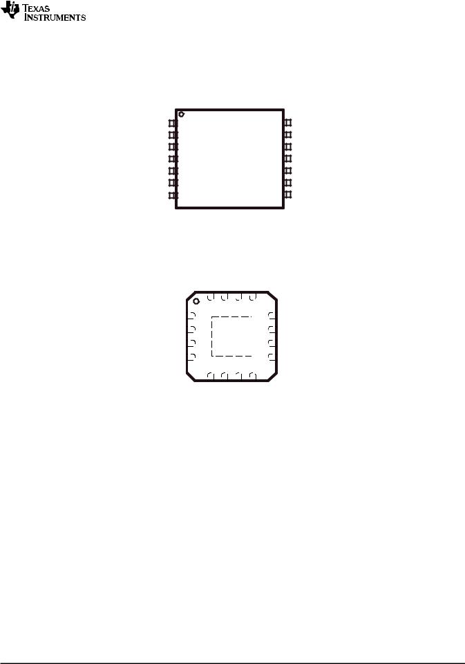
Device Pinout, MSP430G2x01 |
|
|
|
|
|
|
|
N or PW PACKAGE |
|
|
|
|
|
(TOP VIEW) |
|
|
|
DVCC |
1 |
14 |
|
DVSS |
|
P1.0/TA0CLK/ACLK |
2 |
13 |
|
XIN/P2.6/TA0.1 |
|
P1.1/TA0.0 |
3 |
12 |
|
XOUT/P2.7 |
|
P1.2/TA0.1 |
4 |
11 |
|
TEST/SBWTCK |
|
|
|
|
|
|
|
P1.3 |
5 |
10 |
RST/NMI/SBWTDIO |
||
P1.4/SMCLK/T CK |
6 |
9 |
P1.7/TDO/TDI |
||
P1.5/TA0.0/TMS |
7 |
8 |
P1.6/TA0.1/TDI/TCLK |
||
NOTE: See port schematics in Application Information for detailed I/O information.
RSA PACKAGE (TOP VIEW)
|
DVCC |
NC |
DVSS |
NC |
|
|
|
16 |
15 14 13 |
|
|
||
P1.0/TA0CLK/ACLK |
1 |
|
|
12 |
XIN/P2.6/TA0.1 |
|
P1.1/TA0.0 |
2 |
|
|
11 |
XOUT/P2.7 |
|
P1.2/TA0.1 |
3 |
|
|
10 |
TEST/SBWTCK |
|
|
|
|
|
|
|
|
P1.3 |
4 |
|
|
9 |
RST/NMI/SBWTDIO |
|
|
5 |
6 |
7 |
8 |
|
|
|
P1.4/SMCLK/TCK |
P1.5/TA0.0/TMS |
P1.6/TA0.1/TDI/TCLK |
P1.7/TDO/TDI |
|
|
NOTE: See port schematics in Application Information for detailed I/O information.
Copyright © 2010–2011, Texas Instruments Incorporated |
Submit Documentation Feedback |
3 |

MSP430G2x11
MSP430G2x01
SLAS695G –FEBRUARY 2010–REVISED DECEMBER 2011 |
|
|
|
www.ti.com |
Device Pinout, MSP430G2x11 |
|
|
|
|
|
|
N or PW PACKAGE |
|
|
|
|
(TOP VIEW) |
|
|
DVCC |
1 |
14 |
DVSS |
|
P1.0/TA0CLK/ACLK/CA0 |
2 |
13 |
XIN/P2.6/TA0.1 |
|
P1.1/TA0.0/CA1 |
3 |
12 |
XOUT/P2.7 |
|
P1.2/TA0.1/CA2 |
4 |
11 |
TEST/SBWTCK |
|
|
|
|
|
|
P1.3/CAOUT/CA3 |
5 |
10 |
RST/NMI/SBWTDIO |
|
P1.4/SMCLK/CA4/TCK |
6 |
9 |
P1.7/CAOUT/CA7/TDO/TDI |
|
P1.5/TA0.0/CA5/TMS |
7 |
8 |
P1.6/TA0.1/CA6/TDI/TCLK |
|
NOTE: See port schematics in Application Information for detailed I/O information.
RSA PACKAGE (TOP VIEW)
|
DVCC |
NC |
DVSS |
NC |
|
|
|
16 |
15 14 13 |
|
|
||
P1.0/TA0CLK/ACLK/CA0 |
1 |
|
|
12 |
XIN/P2.6/TA0.1 |
|
P1.1/TA0.0/CA1 |
2 |
|
|
11 |
XOUT/P2.7 |
|
P1.2/TA0.1/CA2 |
3 |
|
|
10 |
TEST/SBWTCK |
|
P1.3/CAOUT/CA3 |
4 |
|
|
9 |
|
|
|
|
RST/NMI/SBWTDIO |
||||
|
5 |
6 |
7 |
8 |
|
|
|
P1.4/SMCLK/CA4/TCK |
P1.5/TA0.0/CA5/TMS |
P1.6/TA0.1/CA6/TDI/TCLK |
P1.7/CAOUT/CA7/TDO/TDI |
|
|
NOTE: See port schematics in Application Information for detailed I/O information.
4 |
Submit Documentation Feedback |
Copyright © 2010–2011, Texas Instruments Incorporated |

MSP430G2x11
MSP430G2x01
www.ti.com |
SLAS695G –FEBRUARY 2010 –REVISED DECEMBER 2011 |
Functional Block Diagram, MSP430G2x11
XIN |
XOUT |
|
DVCC |
DVSS |
|
P1.x |
P2.x |
|
|
|
|
|
|
8 |
2 |
|
|
ACLK |
|
|
|
|
|
Clock |
|
|
|
|
Port P1 |
Port P2 |
|
|
|
|
|
|
|
||
System |
SMCLK |
Flash |
RAM |
|
8 I/O |
2 I/O |
|
|
|
|
|
|
|||
|
|
|
2KB |
|
|
Interrupt |
Interrupt |
|
|
|
128B |
|
capability |
capability |
|
|
MCLK |
|
1KB |
|
|||
|
|
|
|
pullup/down |
pullup/down |
||
|
|
|
|
|
|
||
|
|
|
|
|
|
resistors |
resistors |
16MHz |
MAB |
|
|
|
|
||
CPU |
|
|
|
|
|
|
|
incl. 16 |
|
|
|
|
|
|
|
Registers |
MDB |
|
|
|
|
||
Emulation |
|
|
|
|
|
|
|
2BP |
|
|
|
Comp_A+ Watchdog Timer0_A2 |
|
||
|
|
|
Brownout |
|
WDT+ |
|
|
JTAG |
|
Protection |
8 |
|
2 CC |
|
|
Interface |
|
|
Channels |
15-Bit |
Registers |
|
|
Spy-Bi |
|
|
|
|
|
|
|
Wire |
|
|
|
|
|
|
|
|
|
|
RST/NMI |
|
|
|
|
Functional Block Diagram, MSP430G2x01
XIN XOUT |
DVCC |
DVSS |
P1.x |
P2.x |
||||||
|
|
|
|
|
|
|
|
8 |
|
2 |
|
|
|
|
|
|
|
|
|
||
|
|
|
|
|
|
|
|
|
|
|
|
|
|
|
|
|
|
|
|
|
|
|
|
|
|
|
|
|
|
|
|
|
|
|
|
|
|
|
|
|
|
|
|
|
ACLK |
|
|
|
|
|
Clock |
|
|
|
|
Port P1 |
Port P2 |
|
Flash |
|
|
|
|
|
System |
SMCLK |
|
|
|
|
|
|
RAM |
|
8 I/O |
2 I/O |
||
|
|
|
||||
|
|
|
|
|||
|
|
2KB |
|
|
Interrupt |
Interrupt |
MCLK |
|
1KB |
128B |
|
capability |
capability |
|
0.5KB |
|
|
pull-up/down pull-up/down |
||
|
|
|
|
|||
|
|
|
|
|
resistors |
resistors |
16MHz |
MAB |
|
|
|
|
|
CPU |
|
|
|
|
|
|
incl. 16 |
|
|
|
|
|
|
Registers |
MDB |
|
|
|
|
|
Emulation |
|
|
|
|
|
|
2BP |
|
|
|
Watchdog |
Timer0_A2 |
|
|
|
Brownout |
|
WDT+ |
|
|
JTAG |
|
Protection |
|
|
2 CC |
|
Interface |
|
|
|
15-Bit |
Registers |
|
Spy-Bi |
|
|
|
|
|
|
Wire |
|
|
|
|
|
|
|
|
RST/NMI |
|
|
|
|
Copyright © 2010–2011, Texas Instruments Incorporated |
Submit Documentation Feedback |
5 |

MSP430G2x11
MSP430G2x01
SLAS695G –FEBRUARY 2010–REVISED DECEMBER 2011 www.ti.com
|
|
|
|
|
|
|
|
Table 2. Terminal Functions |
|
|
|
|
|
|
|
|
|
|
|
|
TERMINAL |
|
|
|
||
|
|
|
|
|
|
|
|
|
|
|
|
|
NO. |
|
I/O |
DESCRIPTION |
|
|
|
NAME |
|
|
|
|
||
|
|
|
14 |
|
16 |
|
|
|
|
|
|
|
N, PW |
|
RSA |
|
|
|
|
|
|
|
|
|
|
|
|
P1.0/ |
|
|
|
|
|
General-purpose digital I/O pin |
|
|
TA0CLK/ |
|
2 |
|
1 |
I/O |
Timer0_A, clock signal TACLK input |
|
|
ACLK/ |
|
|
ACLK signal output |
||||
|
|
|
|
|
|
|||
|
CA0 |
|
|
|
|
|
Comparator_A+, CA0 input(1) |
|
|
P1.1/ |
|
|
|
|
|
General-purpose digital I/O pin |
|
|
TA0.0/ |
|
3 |
|
2 |
I/O |
Timer0_A, capture: CCI0A input, compare: Out0 output |
|
|
CA1 |
|
|
|
|
|
Comparator_A+, CA1 input(1) |
|
|
P1.2/ |
|
|
|
|
|
General-purpose digital I/O pin |
|
|
TA0.1/ |
|
4 |
|
3 |
I/O |
Timer0_A, capture: CCI1A input, compare: Out1 output |
|
|
CA2 |
|
|
|
|
|
Comparator_A+, CA2 input(1) |
|
|
P1.3/ |
|
|
|
|
|
General-purpose digital I/O pin |
|
|
CA3/ |
|
5 |
|
4 |
I/O |
Comparator_A+, CA3 input(1) |
|
|
CAOUT |
|
|
|
|
|
Comparator_A+, output(1) |
|
|
P1.4/ |
|
|
|
|
|
General-purpose digital I/O pin |
|
|
SMCLK/ |
|
6 |
|
5 |
I/O |
SMCLK signal output |
|
|
CA4/ |
|
|
Comparator_A+, CA4 input(1) |
||||
|
|
|
|
|
|
|||
|
TCK |
|
|
|
|
|
JTAG test clock, input terminal for device programming and test |
|
|
|
|
|
|
|
|
|
|
|
P1.5/ |
|
|
|
|
|
General-purpose digital I/O pin |
|
|
TA0.0/ |
|
7 |
|
6 |
I/O |
Timer0_A, compare: Out0 output |
|
|
CA5/ |
|
|
Comparator_A+, CA5 input(1) |
||||
|
|
|
|
|
|
|||
|
TMS |
|
|
|
|
|
JTAG test mode select, input terminal for device programming and test |
|
|
|
|
|
|
|
|
|
|
|
P1.6/ |
|
|
|
|
|
General-purpose digital I/O pin |
|
|
TA0.1/ |
|
8 |
|
7 |
I/O |
Timer0_A, compare: Out1 output |
|
|
CA6/ |
|
|
Comparator_A+, CA6 input(1) |
||||
|
|
|
|
|
|
|||
|
TDI/TCLK |
|
|
|
|
|
JTAG test data input or test clock input during programming and test |
|
|
|
|
|
|
|
|
|
|
|
P1.7/ |
|
|
|
|
|
General-purpose digital I/O pin |
|
|
CA7/ |
|
9 |
|
8 |
I/O |
CA7 input(1) |
|
|
CAOUT/ |
|
|
Comparator_A+, output(1) |
||||
|
|
|
|
|
|
|||
|
TDO/TDI(2) |
|
|
|
|
|
JTAG test data output terminal or test data input during programming and test |
|
|
XIN/ |
|
|
|
|
|
Input terminal of crystal oscillator |
|
|
P2.6/ |
|
13 |
|
12 |
I/O |
General-purpose digital I/O pin |
|
|
TA0.1 |
|
|
|
|
|
Timer0_A, compare: Out1 output |
|
|
|
|
|
|
|
|
|
|
|
XOUT/ |
|
12 |
|
11 |
I/O |
Output terminal of crystal oscillator(3) |
|
|
P2.7 |
|
|
General-purpose digital I/O pin |
||||
|
|
|
|
|
|
|||
|
|
|
|
|
|
|
|
|
|
|
|
|
|
|
|
|
Reset |
|
RST/ |
|
|
|
|
|
||
|
NMI/ |
|
10 |
|
9 |
I |
Nonmaskable interrupt input |
|
|
SBWTDIO |
|
|
|
|
|
Spy-Bi-Wire test data input/output during programming and test |
|
|
|
|
|
|
|
|
|
|
|
TEST/ |
|
11 |
|
10 |
I |
Selects test mode for JTAG pins on Port 1. The device protection fuse is connected to TEST. |
|
|
SBWTCK |
|
|
Spy-Bi-Wire test clock input during programming and test |
||||
|
|
|
|
|
|
|||
|
|
|
|
|
|
|
|
|
|
DVCC |
|
1 |
|
16 |
NA |
Supply voltage |
|
|
|
|
|
|
|
|
|
|
|
DVSS |
|
14 |
|
14 |
NA |
Ground reference |
|
|
|
|
|
|
|
|
|
|
|
NC |
|
- |
|
15 |
NA |
Not connected |
|
|
|
|
|
|
|
|
|
|
|
QFN Pad |
|
- |
|
Pad |
NA |
QFN package pad connection to VSS recommended. |
|
(1)MSP430G2x11 only
(2)TDO or TDI is selected via JTAG instruction.
(3)If XOUT/P2.7 is used as an input, excess current flows until P2SEL.7 is cleared. This is due to the oscillator output driver connection to this pad after reset.
6 |
Submit Documentation Feedback |
Copyright © 2010–2011, Texas Instruments Incorporated |