Fig.14.19. Schematic of the gas turbine starters:
1 – compressor; 2 – turbine; 3 – reduction gear; 4 – hydraulic clutch; 5 – ratchet clutch; 6 – free turbine
Gas turbine starter with hydraulic clutch consists of (see Fig. 14.19, b):
- axial or centrifugal compressor;
- annular spiral (helical, curtailed type) combustion chamber;
- axial single-stage turbine;
- reduction gear, three couplings – roller free wheel, hydraulic and ratchet with "centrifugal" rotated ratchets;
- exhaust unit.
The free wheel coupling links gas turbine starter rotor with the direct acting electric starter at a starting stage.
The hydraulic clutch provides smooth starting. After gas turbine is started and its rotor reaches operational rotational speed the centrifugal sensor of the fuel regulator is opened by valve an oil supply from an oil pump (under pressure of 0,35...0,45 MPa) to internal cavity of a hydraulic clutch (see Fig. 14.20). As a result, the coupling begins to transmit torque smoothly to starter output shaft, which is connected with started engine rotor through the ratchet coupling.
The hydraulic clutch consists of two parts – driving and driven. The driving part is a hydropump with radial blades, and driven part is hydromotor of the same type. The driving part is rotated from gas turbine starter rotor. As a result, oil between the blades of a driving part gets the kinetic energy. It is transmitted then to blades of a driven part and will be converted to mechanical work of its rotation. Efficiency of the hydraulic clutch at the initial moment is equal to zero (all energy thus is spent on oil heating). During smoothly varying increase of the coupling driven part rotational speed up to nominal value, the efficiency of the hydraulic clutch increases up to maximum value. Thus the rotational speed of a driven part of the coupling is 4...6 % less than the rotational speed of a driving part.
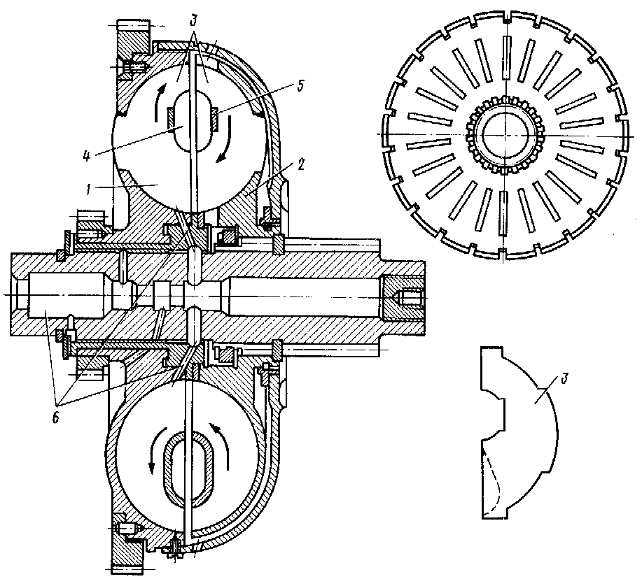
Fig. 14.20. Hydraulic clutch:
1 – hydropump; 2 – turbine; 3 – blades; 4, 5 – rings; 6 – oil supply channels
Gas turbine starter is disconnected by fuel supply discontinuance in the starter engine combustion chamber. During starter rotor stop oil from internal cavity of the hydraulic clutch is discharged in the main line of scavenging and the coupling is set ready for the following engine start-up. The disconnection of gas turbine starter rotor and started engine is provided by the ratchet coupling.
Gas turbine starter with the differential reduction gear (Fig. 14.19, a) consists of a compressor, a combustion chamber and a turbine, which through the differential reduction gear transmits a torque in two directions – to starter compressor rotor and to an output shaft, jointed with started engine rotor.
At the initial moment of starter compressor rotor motoring by the turbine, when compressor rotor antitorque moment is insignificant, the main torque from the turbine is transmitted to the started engine rotor. With increase in rotational speed of a compressor rotor and its stabilization at a maximum level by propellant consumption limitation a part of turbine power, which is transmitted to starter output shaft, is augmented proportionally to rotational speed of this shaft. Thus the torque on starter output shaft will be constant (МSD = М0 = const).
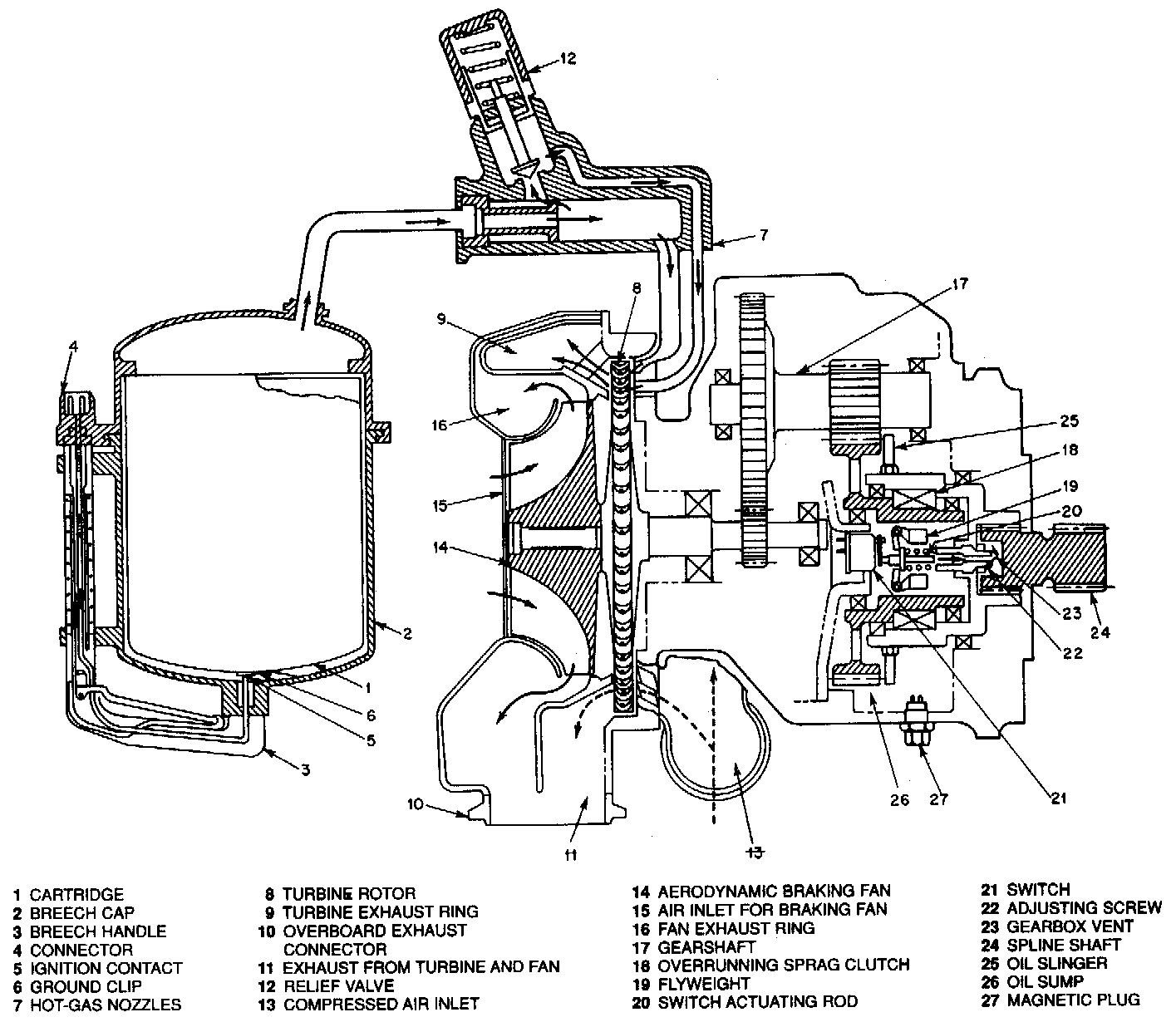
Originally, cartridge or solid-propellant starters were constructed to operate solely by means of high-pressure, high-temperature gas generated by the burning of a solid-propellant charge. Changes in the cartridge-type starter have added the possibility of starting with compressed air from an external source.
The turbine rotor in powder turbine starter (cartridge starter) is rotated under affection of powder gases energy (Fig. 14.21.), which is received in special chambers during combustion of pyrocartridges (up to 6 pyrocartridges with mass of 1…4 kg of smokeless powder or ammonium nitrate). It is connected with engine rotor through the reduction gear and clutch gear.