

a
DSP Microcomputer
ADSP-2171/ADSP-2172/ADSP-2173
FEATURES
30 ns Instruction Cycle Time (33 MIPS) from
16.67 MHz Crystal at 5.0 V
50 ns Instruction Cycle Time (20 MIPS) from 10 MHz Crystal at 3.3 V
ADSP-2100 Family Code & Function Compatible with New Instruction Set Enhancements for Bit Manipulation Instructions, Multiplication Instructions, Biased Rounding, and Global Interrupt Masking
Bus Grant Hang Logic
2K Words of On-Chip Program Memory RAM
2K Words of On-Chip Data Memory RAM
8K Words of On-Chip Program Memory ROM (ADSP-2172)
8- or 16-Bit Parallel Host Interface Port
300 mW Typical Power Dissipation at 5.0 V at 30 ns 70 mW Typical Power Dissipation at 3.3 V at 50 ns
Powerdown Mode Featuring Less than 0.55 mW (ADSP- 2171/ADSP-2172) or 0.36 mW (ADSP-2173) CMOS Standby Power Dissipation with 100 Cycle Recovery from Powerdown
Dual Purpose Program Memory for Both Instruction and Data Storage
Independent ALU, Multiplier/Accumulator, and Barrel Shifter Computational Units
Two Independent Data Address Generators Powerful Program Sequencer Provides
Zero Overhead Looping Conditional Instruction Execution
Two Double-Buffered Serial Ports with Companding Hardware and Automatic Data Buffering
Programmable 16-Bit Interval Timer with Prescaler Programmable Wait State Generation
Automatic Booting of Internal Program Memory from Byte-Wide External Memory, e.g., EPROM, or Through Host Interface Port
Stand-Alone ROM Execution (Optional) Single-Cycle Instruction Execution Single-Cycle Context Switch Multifunction Instructions
Three Edgeor Level-Sensitive External Interrupts Low Power Dissipation in Standby Mode 128-Lead TQFP and 128-Lead PQFP
GENERAL DESCRIPTION
The ADSP-2171, ADSP-2172, and ADSP-2173 are single-chip microcomputers optimized for digital signal processing (DSP) and other high-speed numeric processing applications. The ADSP-2171 and ADSP-2172 are designed for 5.0 V applications. The ADSP-2173 is designed for 3.3 V applications. The ADSP-2172 also has 8K words (24-bit) of program ROM.
REV. A
Information furnished by Analog Devices is believed to be accurate and reliable. However, no responsibility is assumed by Analog Devices for its use, nor for any infringements of patents or other rights of third parties which may result from its use. No license is granted by implication or otherwise under any patent or patent rights of Analog Devices.
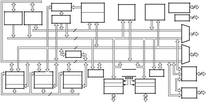
FUNCTIONAL BLOCK DIAGRAM
|
|
|
PROGRAM |
MEMORY |
POWERDOWN |
|
|
|
|
CONTROL |
|||
|
|
|
ROM |
|
||
|
|
|
|
LOGIC |
||
DATA |
|
8K x 24 |
|
|||
|
|
|
||||
|
|
|
|
|||
ADDRESS |
PROGRAM |
PROGRAM |
DATA |
|
||
GENERATORS |
FLAGS |
|||||
SEQUENCER |
RAM |
MEMORY |
||||
DAG 1 |
DAG 2 |
|
2K x 24 |
2K x 16 |
|
|
|
|
|
|
|
EXTERNAL |
|
|
|
|
|
|
ADDRESS |
|
|
|
PROGRAM MEMORY ADDRESS |
|
BUS |
||
|
|
DATA MEMORY ADDRESS |
|
|
||
|
|
PROGRAM MEMORY DATA |
|
|
||
|
|
DATA MEMORY DATA |
|
|
|
|
|
|
|
|
|
EXTERNAL |
|
|
|
|
|
|
DATA |
|
ARITHMETIC UNITS |
|
TIMER |
BUS |
|||
|
|
|||||
|
|
|
SERIAL PORTS |
HOST |
||
ALU |
MAC SHIFTER |
|
||||
|
|
INTERFACE |
||||
|
|
|
SPORT 0 SPORT 1 |
|
||
|
|
|
|
PORT |
||
ADSP-2100 BASE
ARCHITECTURE
The ADSP-217x combines the ADSP-2100 base architecture (three computational units, data address generators, and a program sequencer) with two serial ports, a host interface port, a programmable timer, extensive interrupt capabilities, and onchip program and data memory.
In addition, the ADSP-217x supports new instructions, which include bit manipulations–bit set, bit clear, bit toggle, bit test– new ALU constants, new multiplication instruction (x squared), biased rounding, and global interrupt masking, for increased flexibility. The ADSP-217x also has a Bus Grant Hang Logic
(BGH) feature.
The ADSP-217x provides 2K words (24-bit) of program RAM and 2K words (16-bit) of data memory. The ADSP-2172 provides an additional 8K words (24-bit) of program ROM. Powerdown circuitry is also provided to meet the low power needs of battery operated portable equipment. The ADSP-217x is available in 128-pin TQFP and 128-pin PQFP packages.
Fabricated in a high-speed, double metal, low power, CMOS process, the ADSP-217X operates with a 30 ns instruction cycle time. Every instruction can execute in a single processor cycle.
The ADSP-217x’s flexible architecture and comprehensive instruction set allow the processor to perform multiple operations in parallel. In one processor cycle the ADSP-217x can:
∙generate the next program address
∙fetch the next instruction
∙perform one or two data moves
∙update one or two data address pointers
∙perform a computational operation
This takes place while the processor continues to:
∙receive and transmit data through the two serial ports
∙receive and/or transmit data through the host interface port
∙decrement timer
©Analog Devices, Inc., 1995
One Technology Way, P.O. Box 9106, Norwood, MA 02062-9106, U.S.A. Tel: 617/329-4700 Fax: 617/326-8703
ADSP-2171/ADSP-2172/ADSP-2173
Development System
The ADSP-2100 Family Development Software, a complete set of tools for software and hardware system development, supports the ADSP-217x. The System Builder provides a high-level method for defining the architecture of systems under development. The Assembler has an algebraic syntax that is easy to program and debug. The Linker combines object files into
an executable file. The Simulator provides an interactive instruction-level simulation with a reconfigurable user interface to display different portions of the hardware environment. A PROM Splitter generates PROM programmer compatible files. The C Compiler, based on the Free Software Foundation’s GNU C Compiler, generates ADSP-217x assembly source code. The Runtime Library includes over 100 ANSI-standard mathematical and DSP-specific functions.
EZ-Tools, low cost, easy-to-use hardware tools, also support the ADSP-217x.
The ADSP-217x EZ-ICE® Emulator aids in the hardware debugging of ADSP-217x systems. The emulator consists of hardware, host computer resident software, the emulator probe, and the pin adaptor. The emulator performs a full range of emulation functions including stand-alone operation or operation in the target, setting up to 20 breakpoints, single-step or full-speed operation in the target, examining and altering registers and memory values, and PC upload/download functions. If you plan to use the emulator, you should consider the emulator’s restrictions (differences between emulator and processor operation).
The EZ-LAB® Evaluation Board is a PC plug-in card, but it can operate in stand-alone mode. The evaluation board/system development board executes EPROM-based or downloaded programs. Modular Analog Front End daughter cards with different codecs will be made available.
EZ-ICE and EZ-LAB are registered trademarks of Analog Devices, Inc.
Additional Information
This data sheet provides a general overview of ADSP-217x functionality. For additional information on the architecture and instruction set of the processor, refer to the ADSP-2100 Family User’s Manual. For more information about the Development System and ADSP-217x programmer’s reference information, refer to the ADSP-2100 Family Assembler Tools & Simulator Manual.
ARCHITECTURE OVERVIEW
Figure 1 is an overall block diagram of the ADSP-217x. The processor contains three independent computational units: the ALU, the multiplier/accumulator (MAC) and the shifter. The computational units process 16-bit data directly and have provisions to support multiprecision computations. The ALU performs a standard set of arithmetic and logic operations; division primitives are also supported. The MAC performs single-cycle multiply, multiply/add and multiply/subtract operations with 40 bits of accumulation. The shifter performs logical and arithmetic shifts, normalization, denormalization, and derive exponent operations. The shifter can be used to efficiently implement numeric format control including multiword and block floating-point representations.
The internal result (R) bus directly connects the computational units so that the output of any unit may be the input of any unit on the next cycle.
A powerful program sequencer and two dedicated data address generators ensure efficient delivery of operands to these computational units. The sequencer supports conditional jumps, subroutine calls and returns in a single cycle. With internal loop counters and loop stacks, the ADSP-217x executes looped code with zero overhead; no explicit jump instructions are required to maintain the loop.
|
|
INSTRUCTION |
PROGRAM ROM |
|
|
|
POWER DOWN |
|
2 |
|
|
|
|
|
CONTROL |
|
|
||
|
|
REGISTER |
DATA |
|
BOOT |
|
|
||
|
|
8K X 24 |
|
|
|
||||
|
|
|
LOGIC |
|
|
||||
|
|
|
|
SRAM |
|
ADDRESS |
|
|
|
DATA |
DATA |
|
|
|
|
|
|
||
|
PROGRAM SRAM |
2K X 16 |
|
GENERATOR |
|
|
3 |
||
ADDRESS |
ADDRESS |
PROGRAM |
|
|
|
FLAGS |
|
|
|
2K X 24 |
|
|
|
|
|
||||
GENERATOR |
GENERATOR |
|
|
|
|
|
|||
SEQUENCER |
|
|
|
|
|
|
|
||
#1 |
#2 |
|
|
|
|
|
|
|
|
|
|
|
|
|
|
EXTERNAL |
|||
|
|
|
|
|
|
|
|
||
|
|
14 |
PMA BUS |
|
|
|
|
|
ADDRESS |
|
|
|
|
|
|
|
BUS |
||
|
|
|
|
|
|
|
|
|
|
|
|
|
|
|
|
|
MUX |
14 |
|
|
|
14 |
DMA BUS |
|
|
|
|
|
|
|
|
|
|
|
|
|
|
||
|
|
24 |
PMD BUS |
|
|
|
|
EXTERNAL |
|
|
|
|
|
|
|
|
DATA |
||
|
|
|
|
|
|
|
|
|
|
|
|
|
|
|
|
|
|
|
BUS |
|
|
BUS |
|
|
|
|
|
|
24 |
|
|
|
|
|
|
MUX |
|
|
|
|
|
EXCHANGE |
|
|
|
|
|
|
|
|
|
|
|
|
|
|
|
|
|
|
|
16 |
DMD BUS |
|
|
|
|
|
|
|
|
|
CONTROL |
COMPANDING |
TIMER |
HIP |
11 |
||
INPUT REGS |
INPUT REGS |
INPUT REGS |
|
||||||
LOGIC |
CIRCUITRY |
|
CONTROL |
||||||
|
|
|
|
|
|||||
ALU |
MAC |
SHIFTER |
TRANSMIT REG |
TRANSMIT REG |
|
|
HIP |
||
|
|
|
|
|
|||||
OUTPUT REGS |
OUTPUT REGS |
OUTPUT REGS |
RECEIVE REG |
|
RECEIVE REG |
|
|
DATA |
|
|
|
|
BUS |
||||||
SERIAL |
|
|
SERIAL |
|
|
||||
|
|
|
|
|
HIP |
16 |
|||
|
16 |
|
PORT 0 |
|
|
PORT 1 |
|
||
|
R BUS |
|
|
|
|
REGISTERS |
|||
|
5 |
|
|
5 |
|
|
|
||
|
|
|
|
|
|
|
|
||
Figure 1. ADSP-217x Block Diagram
–2– |
REV. A |

ADSP-2171/ADSP-2172/ADSP-2173
Two data address generators (DAGs) provide addresses for simultaneous dual operand fetches (from data memory and program memory). Each DAG maintains and updates four address pointers. Whenever the pointer is used to access data (indirect addressing), it is post-modified by the value of one of four possible modify registers. A length value may be associated with each pointer to implement automatic modulo addressing for circular buffers.
Efficient data transfer is achieved with the use of five internal buses.
∙Program Memory Address (PMA) Bus
∙Program Memory Data (PMD) Bus
∙Data Memory Address (DMA) Bus
∙Data Memory Data (DMD) Bus
∙Result (R) Bus
The two address buses (PMA and DMA) share a single external address bus, allowing memory to be expanded off-chip, and the two data buses (PMD and DMD) share a single external data bus.
Program memory can store both instructions and data, permitting the ADSP-217x to fetch two operands in a single cycle, one from program memory and one from data memory. The ADSP217x can fetch an operand from on-chip program memory and the next instruction in the same cycle.
The memory interface supports slow memories and memorymapped peripherals with programmable wait state generation. External devices can gain control of external buses with bus request/grant signals (BR and BG). One execution mode (Go Mode) allows the ADSP-217x to continue running from internal memory. Normal execution mode requires the processor to halt while buses are granted.
In addition to the address and data bus for external memory connection, the ADSP-217x has a configurable 8- or 16-bit Host Interface Port (HIP) for easy connection to a host processor. The HIP is made up of 16 data/address pins and 11 control pins. The HIP is extremely flexible and provides a simple interface to a variety of host processors. For example, the Motorola 68000 series, the Intel 80C51 series and the Analog Devices’ ADSP-2101 can be easily connected to the HIP. The host processor can initialize the ASDP-217x’s on-chip memory through the HIP.
The ADSP-217x can respond to eleven interrupts. There can be up to three external interrupts, configured as edge or level sensitive, and eight internal interrupts generated by the Timer, the Serial Ports (“SPORTs”), the HIP, the powerdown circuitry, and software. There is also a master RESET signal.
The two serial ports provide a complete synchronous serial interface with optional companding in hardware and a wide variety of framed or frameless data transmit and receive modes of operation. Each port can generate an internal programmable serial clock or accept an external serial clock.
Boot circuitry provides for loading on-chip program memory automatically from byte-wide external memory. After reset, seven wait states are automatically generated. This allows, for example, a 30 ns ADSP-217x to use an external 200 ns EPROM as boot memory. Multiple programs can be selected
and loaded from the EPROM with no additional hardware. The on-chip program memory can also be initialized through the HIP.
The ADSP-217x features three general-purpose flag outputs whose states can be simultaneously changed through software. You can use these outputs to signal an event to an external device. In addition, the data input and output pins on SPORT1 can be alternatively configured as an input flag and an output flag.
A programmable interval timer generates periodic interrupts. A 16-bit count register (TCOUNT) is decremented every n processor cycles, where n-l is a scaling value stored in an 8-bit register (TSCALE). When the value of the count register reaches zero, an interrupt is generated and the count register is reloaded from a 16-bit period register (TPERIOD).
The ADSP-217x instruction set provides flexible data moves and multifunction (one or two data moves with a computation) instructions. Every instruction can be executed in a single processor cycle. The ADSP-217x assembly language uses an algebraic syntax for ease of coding and readability. A comprehensive set of development tools supports program development.
Serial Ports
The ADSP-217x incorporates two complete synchronous serial ports (SPORT0 and SPORT1) for serial communications and multiprocessor communication.
Here is a brief list of the capabilities of the ADSP-217x SPORTs. Refer to the ADSP-2100 Family User’s Manual for further details.
∙SPORTs are bidirectional and have a separate, doublebuffered transmit and receive section.
∙SPORTs can use an external serial clock or generate their own serial clock internally.
∙SPORTs have independent framing for the receive and transmit sections. Sections run in a frameless mode or with frame synchronization signals internally or externally generated.
Frame sync signals are active high or inverted, with either of two pulse widths and timings.
∙SPORTs support serial data word lengths from 3 to 16 bits and provide optional A-law and μ-law companding according to CCITT recommendation G.711.
∙SPORT receive and transmit sections can generate unique interrupts on completing a data word transfer.
∙SPORTs can receive and transmit an entire circular buffer of data with only one overhead cycle per data word. An interrupt is generated after a data buffer transfer.
∙SPORT0 has a multichannel interface to selectively receive and transmit a 24 or 32 word, time-division multiplexed, serial bitstream.
∙SPORT1 can be configured to have two external interrupts (IRQ0 and IRQ1) and the Flag In and Flag Out signals. The internally generated serial clock may still be used in this configuration.
REV. A |
–3– |

ADSP-2171/ADSP-2172/ADSP-2173
Pin Description
The ADSP-217x is available in 128-lead TQFP and 128-lead PQFP packages. Table I contains the pin descriptions.
Table I. ADSP-217x Pin List
Pin |
# |
|
|
||||||||||||||||
Group |
of |
Input/ |
|
||||||||||||||||
Name |
Pins |
Output Function |
|||||||||||||||||
|
|
|
|
|
|
|
|
|
|
|
|
|
|
|
|
|
|
|
|
Address |
14 |
O |
Address output for program, |
||||||||||||||||
|
|
|
|
|
|
|
|
|
|
|
|
|
|
|
|
|
|
|
data and boot memory spaces |
Data |
24 |
I/O |
Data I/O pins for program |
||||||||||||||||
|
|
|
|
|
|
|
|
|
|
|
|
|
|
|
|
|
|
|
and data memories. Input |
|
|
|
|
|
|
|
|
|
|
|
|
|
|
|
|
|
|
|
only for boot memory space, |
|
|
|
|
|
|
|
|
|
|
|
|
|
|
|
|
|
|
|
with two MSBs used as boot |
|
|
|
|
|
|
|
|
|
|
|
|
|
|
|
|
|
|
|
space addresses. |
|
|
|
|
|
|
|
|
|
|
|
|
|
|
|
|
|
1 |
I |
Processor reset input |
RESET |
|||||||||||||||||||
|
|
|
|
|
|
|
|
|
|
|
|
|
|
|
|
1 |
I |
External interrupt request #2 |
|
IRQ2 |
|||||||||||||||||||
|
|
|
|
|
|
|
|
|
|
|
|
|
|
|
1 |
I |
External bus request input |
||
BR |
|||||||||||||||||||
|
|
|
|
|
|
|
|
|
|
|
|
|
|
1 |
O |
External bus grant output |
|||
BG |
|||||||||||||||||||
|
|
|
|
|
|
|
|
|
|
|
|
|
1 |
O |
External bus grant hang output |
||||
BGH |
|||||||||||||||||||
|
|
|
|
|
|
|
|
|
|
|
|
1 |
O |
External program memory select |
|||||
PMS |
|||||||||||||||||||
|
|
|
|
|
|
|
|
|
|
|
1 |
O |
External data memory select |
||||||
DMS |
|||||||||||||||||||
|
|
|
|
|
|
|
|
|
|
1 |
O |
Boot memory select |
|||||||
BMS |
|||||||||||||||||||
|
|
|
|
|
|
|
|
|
1 |
O |
External memory read enable |
||||||||
RD |
|||||||||||||||||||
|
|
|
|
|
|
|
|
1 |
O |
External memory write enable |
|||||||||
WR |
|||||||||||||||||||
MMAP |
1 |
I |
Memory map select |
||||||||||||||||
CLKIN, |
|
|
|
||||||||||||||||
XTAL |
2 |
I |
External clock or quartz crystal |
||||||||||||||||
|
|
|
|
|
|
|
|
|
|
|
|
|
|
|
|
|
|
|
input |
CLKOUT |
1 |
O |
Processor clock output |
||||||||||||||||
|
|
|
|
|
|
|
1 |
I |
HIP select input |
||||||||||
HSEL |
|||||||||||||||||||
|
|
|
|
|
|
1 |
O |
HIP acknowledge output |
|||||||||||
HACK |
|||||||||||||||||||
HSIZE |
1 |
|
8/16 bit host select input |
||||||||||||||||
|
|
|
|
|
|
|
|
|
|
|
|
|
|
|
|
|
|
|
0 = 16-bit; 1 = 8-bit |
BMODE |
1 |
I |
Boot mode select input |
||||||||||||||||
|
|
|
|
|
|
|
|
|
|
|
|
|
|
|
|
|
|
|
0 = EPROM/data bus; 1 = HIP |
HMD0 |
1 |
I |
Bus strobe select input |
||||||||||||||||
|
|
|
|
|
|
|
|
|
|
|
|
|
|
|
|
|
|
|
0 = RD, WR; 1 = RW, DS |
HMD1 |
1 |
I |
HIP address/data mode select |
||||||||||||||||
|
|
|
|
|
|
|
|
|
|
|
|
|
|
|
|
|
|
|
input 0 = separate; 1 = |
|
|
|
|
|
|
|
|
|
|
|
|
|
|
|
|
|
|
|
multiplexed |
|
/HRW |
1 |
I |
HIP read strobe/read/write |
|||||||||||||||
HRD |
|||||||||||||||||||
|
|
|
|
|
|
|
|
|
|
|
|
|
|
|
|
|
|
|
select input |
|
/ |
|
|
1 |
I |
HIP write strobe/host data |
|||||||||||||
HWR |
HDS |
||||||||||||||||||
|
|
|
|
|
|
|
|
|
|
|
|
|
|
|
|
|
|
|
strobe select input |
HD15–0/ |
|
|
|
||||||||||||||||
HAD15-0 |
16 |
I/O |
HIP data/data and address |
||||||||||||||||
HA2/ALE |
1 |
I |
Host address 2/Address latch |
||||||||||||||||
|
|
|
|
|
|
|
|
|
|
|
|
|
|
|
|
|
|
|
enable input |
HA1–0/ |
|
|
|
||||||||||||||||
Unused |
2 |
I |
Host addresses 1 and 0 inputs |
||||||||||||||||
SPORT0 |
5 |
I/O |
Serial port 0 I/O pins (TFS0, |
||||||||||||||||
|
|
|
|
|
|
|
|
|
|
|
|
|
|
|
|
|
|
|
RFS0, DT0, DR0, SCLK0) |
SPORT1 |
5 |
I/O |
Serial port 1 I/O pins |
||
or |
|
|
|
||
IRQ1 |
|
(TFS1) |
1 |
I |
External interrupt request #1 |
|
|
(RFS1) |
1 |
I |
External interrupt request #0 |
IRQ0 |
|||||
SCLK1 |
1 |
O |
Programmable clock output |
||
FO (DT1) |
1 |
O |
Flag Output pin |
||
FI (DR1) |
1 |
I |
Flag Input pin |
||
FL2–0 |
3 |
O |
General purpose flag output |
||
|
|
|
|
|
pins |
VDD |
6 |
|
Power supply pins |
||
GND |
11 |
|
Ground pins |
||
|
|
1 |
I |
Powerdown pin |
|
PWD |
|||||
PWDACK |
1 |
O |
Powerdown acknowledge pin |
||
|
|
|
|
|
|
Host Interface Port
The ADSP-217x host interface port is a parallel I/O port that allows for an easy connection to a host processor. Through the HIP, the ADSP-217x can be used as a memory-mapped peripheral to a host computer. The HIP can be thought of as an area of dual-ported memory, or mailbox registers, that allow communication between the computational core of the ADSP-217x and the host computer.
The HIP is completely asynchronous. The host processor can write data into the HIP while the ADSP-217x is operating at full speed.
The HIP can be configured with the following pins:
∙HSIZE configures HIP for 8-bit or 16-bit communication with the host processor.
∙BMODE (when MMAP = 0) determines whether the ADSP217x boots from the host processor (through the HIP) or external EPROM (through the data bus).
∙HMD0 configures the bus strobes as separate read and write strobes, or a single read/write select and a host data strobe.
∙HMD1 selects separate address (3-bit) and data (16-bit) buses, or a multiplexed, 16-bit address/data bus with address latch enable.
Tying these pins to appropriate values configures the ADSP217x for straight-wire interface to a variety of industry-standard microprocessors and microcomputers.
In 8-bit reads, the ADSP-217x three-states the upper eight bits of the bus. When the host processor writes an 8-bit value to the HIP, the upper eight bits are all zeros. For additional information refer to the ADSP-2100 Family User’s Manual.
HIP Operation
The HIP contains six data registers (HDR5–0) and two status registers (HSR7–6) with an associated HMASK register for masking interrupts from individual HIP data registers. All HIP data registers are memory-mapped into the internal data memory of the ADSP-217x. HIP transfers can be managed using either interrupts or a polling scheme. These registers are shown in the section “ADSP-217x Registers.”
The HIP allows a software reset to be performed by the host processor. The internal software reset signal is asserted for five ADSP-217x processor cycles.
–4– |
REV. A |
ADSP-2171/ADSP-2172/ADSP-2173
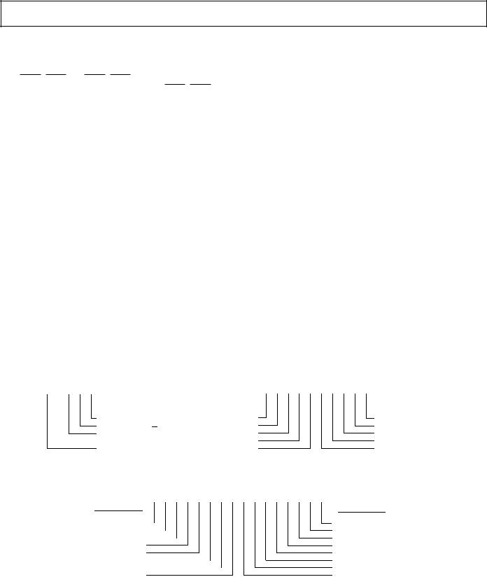
Interrupts
The interrupt controller allows the processor to respond to the eleven possible interrupts and reset with minimum overhead. The ADSP-217x provides up to three external interrupt input pins, IRQ0, IRQ1 and IRQ2. IRQ2 is always available as a dedicated pin; SPORT1 may be reconfigured for IRQ0, IRQ1, and the flags. The ADSP-217x also supports internal interrupts from the timer, the host interface port, the two serial ports, software, and the powerdown control circuit. The interrupt levels are internally prioritized and individually maskable (except powerdown and reset). The input pins can be programmed to be either levelor edge-sensitive. The priorities and vector addresses of all interrupts are shown in Table II, and the interrupt registers are shown in Figure 2.
Interrupts can be masked or unmasked with the IMASK register. Individual interrupt requests are logically ANDed with the bits in IMASK; the highest priority unmasked interrupt is then selected.The powerdown interrupt is nonmaskable.
The ADSP-217x masks all interrupts for one instruction cycle following the execution of an instruction that modifies the IMASK register. This does not affect autobuffering.
The interrupt control register, ICNTL, allows the external interrupts to be either edgeor level-sensitive. Interrupt routines can either be nested with higher priority interrupts taking precedence or processed sequentially.
The IFC register is a write-only register used to force and clear interrupts generated from software.
Table II. Interrupt Priority & Interrupt Vector Addresses
|
|
|
|
|
|
Interrupt Vector |
|
Source of Interrupt |
Address (Hex) |
||||||
|
|
|
|
|
|
|
|
Reset (or Power-Up with PUCR = 1) |
0000 |
(Highest Priority) |
|||||
Powerdown (Nonmaskable) |
002C |
|
|||||
IRQ2 |
|
|
|
|
|
0004 |
|
HIP Write |
0008 |
|
|||||
HIP Read |
000C |
|
|||||
SPORT0 Transmit |
0010 |
|
|||||
SPORT0 Receive |
0014 |
|
|||||
Software Interrupt 1 |
0018 |
|
|||||
Software Interrupt 0 |
001C |
|
|||||
SPORT1 Transmit or |
IRQ1 |
|
0020 |
|
|||
SPORT1 Receive or |
IRQ0 |
|
0024 |
|
|||
Timer |
0028 |
(Lowest Priority) |
|||||
|
|
|
|
|
|
|
|
On-chip stacks preserve the processor status and are automatically maintained during interrupt handling.
The stacks are twelve levels deep to allow interrupt nesting.
The following instructions allow global enable or disable servicing of the interrupts (including powerdown), regardless of the state of IMASK. Disabling the interrupts does not affect autobuffering.
ENA INTS;
DIS INTS;
When you reset the processor, the interrupt servicing is enabled.
|
|
ICNTL |
|
|
|
|
|
|
|
|
|
|
|
|
IMASK |
|
|
|
|
|
|
|
||||
4 |
3 |
2 |
1 |
0 |
|
|
|
|
15 |
14 |
13 |
12 |
11 |
10 |
9 |
8 |
7 |
6 |
5 |
4 |
3 |
2 |
1 |
0 |
|
|
|
0 |
|
|
|
|
|
|
|
|
0 |
0 |
0 |
0 |
0 |
0 |
0 |
0 |
0 |
0 |
0 |
0 |
0 |
0 |
0 |
0 |
1 = enable, 0 = disable |
|
|
|
|
|
|
|
|
|
|
|
|
|
|
|
|
|
|
|
|
|
|
|
|
|
|
|
|
|
|
|
|
|
IRQ0 Sensitivity |
|
|
1 = edge |
|
|
|
|
IRQ2 |
|
|
|
|
|
|
|
|
|
|
Timer |
|
|
|
|
|
|
|
|
|
|
|
|
|
|
|
|
|
|
|
|
|
|||||||
|
|
|
|
|
|
IRQ1 Sensitivity |
|
|
|
|
HIP Write |
|
|
|
|
|
|
|
|
|
|
IRQ0 or SPORT1 Receive |
||||
|
|
|
|
|
|
IRQ2 Sensitivity |
|
|
0 = level |
|
|
|
HIP Read |
|
|
|
|
|
|
|
|
|
|
IRQ1 or SPORT1 Transmit |
||
|
|
|
|
|
|
|
|
|
|
|
|
|
|
|
|
|
|
|
|
|
|
|||||
|
|
|
|
|
|
|
|
|
|
|
SPORT0 Transmit |
|
|
|
|
|
|
|
|
|
|
Software 0 |
||||
|
|
|
|
|
|
Interrupt Nesting |
|
|
SPORT0 Receive |
|
|
|
|
|
|
|
|
|
|
Software 1 |
||||||
|
|
|
|
|
|
1 = enable, 0 = disable |
|
|
|
|
|
|
|
|
|
|
|
|
|
|
|
|
|
|
||
IFC
15 |
14 |
13 |
12 |
11 |
10 |
9 |
8 |
7 |
6 |
5 |
4 |
3 |
2 |
1 |
0 |
0 |
0 |
0 |
0 |
0 |
0 |
0 |
0 |
0 |
0 |
0 |
0 |
0 |
0 |
0 |
0 |
|
|
|
|
|
|
|
|
|
|
|
|
|
|
|
|
INTERRUPT FORCE
IRQ2 
SPORT0 Transmit 
SPORT0 Receive 
Software 1
Software 0
SPORT1 Transmit or IRQ1 
SPORT1 Receive or IRQ0 
Timer
INTERRUPT CLEAR
Timer
SPORT1 Receive or IRQ0 SPORT1 Transmit or IRQ1 Software 0
Software 1 SPORT0 Receive SPORT0 Transmit IRQ2
Figure 2. Interrupt Registers
REV. A |
–5– |

ADSP-2171/ADSP-2172/ADSP-2173
LOW POWER OPERATION
The ADSP-217x has three low power modes that significantly reduce the power dissipation when the device operates under standby conditions. These modes are:
∙Powerdown
∙Idle
∙Slow Idle
The CLKOUT pin may also be disabled to reduce external power dissipation. The CLKOUT pin is controlled by Bit 14 of SPORT0 Autobuffer Control Register, DM[0x3FF3].
Powerdown
The ADSP-217x processor has a low power feature that lets the processor enter a very low power dormant state through hardware or software control. Here is a brief list of powerdown features. Refer to the ADSP-2100 Family User’s Manual, Chapter 9 “System Interface” for detailed information about the powerdown feature.
∙Powerdown mode holds the processor in CMOS standby with a maximum current of less than 100 μA in some modes.
∙Quick recovery from powerdown. The processor begins executing instructions in as few as 100 CLKIN cycles.
∙Support for an externally generated TTL or CMOS processor clock. The external clock can continue running during powerdown without affecting the lowest power rating and 100 CLKIN cycle recovery.
∙Support for crystal operation includes disabling the oscillator to save power (the processor automatically waits 4096 CLKIN cycles for the crystal oscillator to start and stabilize), and letting the oscillator run to allow 100 CLKIN cycle startup.
∙Powerdown is initiated by either the powerdown pin (PWD) or the software powerdown force bit.
∙Interrupt support allows an unlimited number of instructions to be executed before optionally powering down. The powerdown interrupt also can be used as a non-maskable, edge sensitive interrupt.
∙Context clear/save control allows the processor to continue where it left off or start with a clean context when leaving the powerdown state.
∙The RESET pin also can be used to terminate powerdown, and the host software reset feature can be used to terminate powerdown under certain conditions.
∙Powerdown acknowledge pin indicates when the processor has entered powerdown.
Idle
When the ADSP-217x is in the Idle Mode, the processor waits indefinitely in a low power state until an interrupt occurs. When an unmasked interrupt occurs, it is serviced; execution then continues with the instruction following the IDLE instruction.
Slow Idle
The IDLE instruction is enhanced on the ADSP-217x to let the processor’s internal clock signal be slowed during IDLE, further reducing power consumption. The reduced clock frequency, a
programmable fraction of the normal clock rate, is specified by a selectable divisor given in the IDLE instruction. The format of the instruction is
IDLE (n);
where n = 16, 32, 64, or 128. This instruction keeps the processor fully functional, but operating at the slower clock rate. While it is in this state, the processor’s other internal clock signals, such as SCLK, CLKOUT, and timer clock, are reduced by the same ratio. The default form of the instruction, when no clock divisor is given, is the standard IDLE instruction.
When the IDLE (n) instruction is used, it effectively slows down the processor’s internal clock and thus its response time to incoming interrupts––the 1-cycle response time of the standard idle state is increased by n, the clock divisor. When an enabled interrupt is received, the ADSP-217x will remain in the idle state for up to a maximum of n processor cycles (n = 16, 32, 64, or 128) before resuming normal operation.
When the IDLE (n) instruction is used in systems that have an externally generated serial clock (SCLK), the serial clock rate may be faster than the processor’s reduced internal clock rate. Under these conditions, interrupts must not be generated at a faster rate than can be serviced, due to the additional time the processor takes to come out of the idle state (a maximum of n processor cycles).
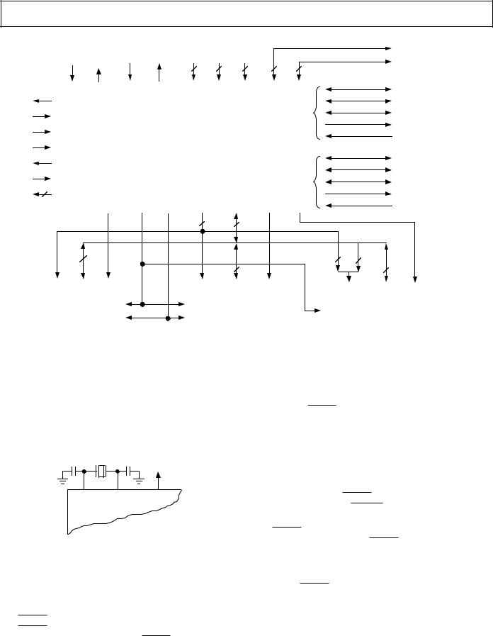
SYSTEM INTERFACE
Figure 3 shows a basic system configuration with the ADSP217x, two serial devices, a host processor, a boot EPROM, and optional external program and data memories. Up to 14K words of data memory and 16K words of program memory can be supported. Programmable wait state generation allows the processor to interface easily to slow memories. The ADSP-217x also provides one external interrupt and two serial ports or three external interrupts and one serial port.
Clock Signals
The ADSP-217x can be clocked by either a crystal or by a TTLcompatible clock signal.
The CLKIN input cannot be halted, changed during operation, or operated below the specified frequency during normal operation. The only exception is while the processor is in the Powerdown State. For additional information, refer to Chapter 9,
ADSP-2100 Family User’s Manual for detailed information on this powerdown feature.
If an external clock is used, it should be a TTL-compatible signal running at half the instruction rate. The signal is connected to the processor’s CLKIN input. When an external clock is used, the XTAL input must be left unconnected.
The ADSP-217x uses an input clock with a frequency equal to half the instruction rate; a 16.67 MHz input clock yields a 30 ns processor cycle (which is equivalent to 33 MHz). Normally, instructions are executed in a single processor cycle. All device timing is relative to the internal instruction clock rate, which is indicated by the CLKOUT signal when enabled.
–6– |
REV. A |
ADSP-2171/ADSP-2172/ADSP-2173
|
|
|
|
|
|
|
|
|
|
|
|
|
|
|
|
|
|
|
|
|
|
|
|
|
|
|
|
|
|
|
|
HIP CONTROL |
|
|
|
|
|
|
HOST |
||||||||
|
|
|
|
|
CLOCK OR |
|
|
|
|
|
|
|
|
|
|
|
|
|
|
|
|
|
|
|
|
|
|
|
|
HIP DATA/ADDR |
|
|
|
|
|
PROCESSOR |
|||||||||||
|
|
|
|
|
CRYSTAL |
|
|
|
|
|
|
|
|
|
|
|
|
|
|
|
|
|
|
|
|
|
|
|
|
|
|
|
|
|
|
|
|
|
|
|
|
(OPTIONAL) |
|||||
|
|
|
|
|
|
|
|
|
|
|
|
|
|
|
|
|
6 |
|
9 |
4 |
|
7 |
|
16 |
|
|
|
|
SCLK |
|
|
|
|
|
|
|
|
|
|||||||||
|
|
|
|
|
|
|
|
|
|
|
|
|
|
|
|
|
|
|
|
|
|
|
|
|
|
|
|
|
|
|
|||||||||||||||||
|
|
|
|
|
|
|
|
|
|
|
|
|
|
|
|
|
|
|
|
|
|
|
|
|
|
|
|
|
|
|
|||||||||||||||||
|
|
|
|
|
|
|
|
|
|
|
|
|
|
|
|
|
|
|
|
|
|
|
|
|
|
|
|
|
|
|
|
|
|
|
|
|
|
|
|
|
|
|
|
||||
|
|
|
CLKIN |
XTAL |
PWD |
PWDACK |
|
VDD |
GND |
|
HOST |
|
|
|
|
|
HIP |
|
|
|
|
|
|
|
|
|
|
|
|||||||||||||||||||
|
|
|
|
|
|
|
|
|
|
|
|
RFS |
|
|
|
|
|
|
|
|
|
||||||||||||||||||||||||||
|
CLKOUT |
|
|
|
|
|
|
|
|
|
|
|
|
|
|
|
|
MODE |
|
|
|
|
|
|
|
|
|
|
|
|
|
|
|
|
|
|
|
||||||||||
|
|
|
|
|
|
|
|
|
|
|
|
|
|
|
|
|
|
|
|
|
|
|
|
|
|
|
|
|
|
|
|
|
|
|
|
|
|
SERIAL DEVICE |
|||||||||
|
|
|
|
|
|
|
|
|
|
|
|
|
|
|
|
|
|
|
|
|
|
|
|
|
|
|
|
|
SERIAL |
|
|
TFS |
|
|
|
|
|
||||||||||
|
|
|
|
|
|
|
|
|
|
|
|
|
|
|
|
|
|
|
|
|
|
|
|
|
|
|
|
|
|
|
|
|
|
|
|
|
|
|
|
||||||||
|
|
|
|
|
|
|
|
|
|
|
|
|
|
|
|
|
|
|
|
|
|
|
|
|
|
|
|
|
|
|
|
|
|
|
|
|
|
|
|
|
|
|
|
||||
|
|
RESET |
|
|
|
|
|
|
|
|
|
|
|
|
|
|
|
|
|
|
|
|
|
|
|
PORT 0 |
|
|
DT |
|
|
|
|
|
(OPTIONAL) |
||||||||||||
|
|
|
|
|
|
|
|
|
|
|
|
|
|
|
|
|
|
|
|
|
|
|
|
|
|
|
|
|
|
|
|
|
|
|
|
|
|
|
|
||||||||
|
|
|
|
|
|
|
|
|
|
|
|
|
|
|
|
|
|
|
|
|
|
|
|
|
|
|
|
|
|
|
|
|
|
DR |
|
|
|
|
|
|
|
|
|
||||
|
IRQ2 |
|
|
|
|
|
|
|
|
|
|
|
|
|
|
|
|
|
|
|
|
|
|
|
|
|
|
|
|
|
|
|
|
|
|
|
|
|
|||||||||
|
|
|
|
|
|
|
|
|
|
|
|
|
|
|
|
ADSP-217x |
|
|
|
|
|
|
|
|
|
|
|
|
|
|
|
|
|
|
|
|
|
|
|
|
|
|
|
||||
|
|
|
|
|
|
|
|
|
|
|
|
|
|
|
|
|
|
|
|
|
|
|
|
|
|
|
|
|
|
|
|
|
|
|
|
|
|
|
|
|
|
|
|||||
|
BR |
|
|
|
|
|
|
|
|
|
|
|
|
|
|
|
|
|
|
|
|
|
|
|
SCLK |
|
|
|
|
|
|
|
|
|
|||||||||||||
|
|
|
|
|
|
|
|
|
|
|
|
|
|
|
|
|
|
|
|
|
|
|
|
|
|
|
|
|
|
|
|
|
|
|
|
|
|
|
|
|
|
|
|
||||
|
|
|
|
|
|
|
|
|
|
|
|
|
|
|
|
|
|
|
|
|
|
|
|
|
|
|
|
|
|
|
|
|
|
|
|
|
|
|
|
|
|
|
|
|
|
|
|
|
BG |
|
|
|
|
|
|
|
|
|
|
|
|
|
|
|
|
|
|
|
|
|
|
|
|
|
|
|
|
RFS or |
|
|
|
|
|
|
|
|
|
|
|||||||
|
|
|
|
|
|
|
|
|
|
|
|
|
|
|
|
|
|
|
|
|
|
|
|
|
|
|
|
|
|
|
|
|
IRQ0 |
|
SERIAL DEVICE |
||||||||||||
|
|
|
|
|
|
|
|
|
|
|
|
|
|
|
|
|
|
|
|
|
|
|
|
|
|
|
|
|
|
|
|
|
|
|
|
|
|
|
|
|
|
|
|
||||
|
|
MMAP |
|
|
|
|
|
|
|
|
|
|
|
|
|
|
|
|
|
|
|
|
|
|
SERIAL |
|
|
TFS or |
IRQ1 |
|
|
|
|
|
|
|
|||||||||||
3 |
|
|
|
|
|
|
|
|
|
|
|
|
|
|
|
|
|
|
|
|
|
|
|
|
|
|
|
|
PORT 1 |
|
|
DT or FO |
|
|
|
|
|
(OPTIONAL) |
|||||||||
|
FL2-0 |
|
|
|
|
|
|
|
|
|
|
|
|
|
|
|
|
|
|
|
|
|
|
|
|
|
|
|
|
|
|
|
|
|
|
|
|
|
|||||||||
|
|
|
|
|
|
|
|
|
|
|
|
|
|
|
|
|
|
|
|
|
|
|
|
|
|
|
|
|
|
|
|
|
|
|
|
|
|
|
|
|
|
|
|||||
|
|
|
|
|
|
|
|
|
|
|
|
|
|
|
|
|
|
|
ADDRESS |
DATA |
|
|
|
|
|
|
|
|
|
|
DR or FI |
|
|
|
|
|
|
|
|
|
|||||||
|
|
|
|
|
|
|
|
PMS |
|
RD |
WR |
|
|
DMS |
|
|
BMS |
|
|
|
|
|
|
|
|
|
|
|
|
|
|
|
|
|
|||||||||||||
|
|
|
|
|
|
|
|
|
|
|
|
|
|
|
|
|
|
|
|
|
|
|
|
|
|
|
|
|
|
|
|
|
|
|
|
|
|
|
|
|
|
|
|
|
|
|
|
|
|
|
|
|
|
|
|
|
|
|
|
|
|
|
|
|
14 |
|
|
24 |
|
|
|
|
|
|
|
|
|
|
|
|
|
|
|
|
|
|
|
|
|
|
|
|
|||
|
|
|
|
|
|
|
|
|
|
|
|
|
|
|
|
|
|
|
|
|
|
|
|
|
|
|
|
|
|
|
|
|
|
|
|
|
|
|
|
|
|
|
|
|
|
||
|
|
|
|
|
|
|
|
|
|
|
|
|
|
|
|
|
|
|
|
|
|
|
|
|
|
|
|
|
|
|
|
|
|
|
|
D23-22 |
|
|
|
|
|
|
|
|
|
||
24 |
|
|
|
|
|
|
|
|
|
|
|
|
|
|
|
|
D23-8 |
|
|
|
|
14 |
|
|
|
|
D15-8 |
|
|
|
|
|
|||||||||||||||
|
|
|
|
|
|
|
|
|
|
|
|
|
|
|
|
|
|
|
|
2 |
|
|
|
|
|
|
|
|
|
|
|||||||||||||||||
|
|
|
|
|
|
|
|
|
|
|
|
|
|
|
|
|
|
|
|
|
|
|
|
|
|
|
|
|
|
|
|
|
|
|
|
|
|
|
|||||||||
|
|
|
|
|
|
|
|
|
|
|
|
|
|
|
|
|
|
|
|
|
|
16 |
|
|
|
|
|
|
8 |
|
|
|
|
|
|||||||||||||
|
|
|
|
|
|
|
|
|
|
|
|
|
|
|
|
|
|
|
|
|
|
|
|
|
|
|
|
|
|
|
|
|
|
|
|
|
|
|
|
|
|
||||||
|
|
|
|
|
|
|
|
|
|
|
|
|
|
|
|
|
|
|
|
|
|
|
|
|
|
|
|
|
|
|
|
|
|
|
|
|
|
|
|
|
|
|
|||||
|
A |
D |
|
CS |
|
|
|
|
|
|
|
|
|
|
A |
|
|
D |
|
CS |
|
|
|
|
|
|
|
|
|
|
|
|
|
|
|
|
|
|
|
|
|
||||||
|
|
|
|
|
|
|
|
|
|
|
|
|
|
|
|
|
|
|
|
|
|
|
A |
|
|
|
D |
|
CS |
|
|||||||||||||||||
|
|
|
|
|
|
|
|
|
|
|
|
|
|
|
|
|
|
|
|
|
|
|
|
|
|
|
|
|
|
|
|
|
|
|
|
|
|
|
|
||||||||
|
|
|
PROGRAM |
|
|
|
|
|
|
|
|
|
|
|
|
|
DATA MEMORY |
|
|
|
|
|
|
|
|
|
|
|
BOOT MEMORY |
|
|||||||||||||||||
|
|
|
|
|
OE |
|
|
|
|
|
|
OE |
|
& |
|
|
|
|
|
|
|
|
|
|
|
|
|
|
|
e.g., EPROM |
|
|
|
|
|||||||||||||
|
|
|
|
MEMORY |
|
|
|
|
|
|
|
|
|
|
|
|
|
|
|
|
|
|
|
|
|
|
|
OE |
|
|
|
|
|
|
|
|
|||||||||||
|
|
|
|
|
|
|
|
|
|
|
|
|
|
|
|
|
PERIPHERALS |
|
|
|
|
|
|
|
|
|
|
|
|
|
|
27C64 |
|
|
|
|
|||||||||||
|
|
|
(OPTIONAL) |
|
|
WE |
|
|
|
|
|
|
WE |
|
|
|
|
|
|
|
|
|
|
|
|
|
|
|
|
|
|
|
|
||||||||||||||
|
|
|
|
|
|
|
|
|
|
|
(OPTIONAL) |
|
|
|
|
|
|
|
|
|
|
|
|
|
|
27C128 |
|
|
|
|
|||||||||||||||||
|
|
|
|
|
|
|
|
|
|
|
|
|
|
|
|
|
|
|
|
|
|
|
|
|
|
|
|
|
|
|
|
|
|
||||||||||||||
|
|
|
|
|
|
|
|
|
|
|
|
|
|
|
|
|
|
|
|
|
|
|
|
|
|
|
|
|
|
|
|
|
|
|
27C256 |
|
|
|
|
||||||||
|
|
|
|
|
|
|
|
|
|
|
|
|
|
|
|
|
|
|
|
|
|
|
|
|
|
|
|
|
|
|
|
|
|
|
|
|
|
|
|
|
|
|
|||||
|
|
|
|
|
|
|
|
|
|
|
|
|
|
|
|
|
|
|
|
|
|
|
|
|
|
|
|
|
|
|
|
|
|
|
|
|
|
|
27C512 |
|
|
|
|
||||
|
|
NOTE: |
|
|
|
|
|
|
|
|
|
|
|
|
|
|
|
|
|
|
|
|
|
|
|
|
|
|
|
|
|
|
|
|
|
|
|
|
|
|
|
|
|
||||
|
|
THE TWO MSBs OF THE DATA BUS ARE USED AS THE MSBs OF THE BOOT EPROM ADDRESS. |
|
|
|
|
|
|
|
|
|
|
|
|
|
||||||||||||||||||||||||||||||||
|
|
THIS IS ONLY REQUIRED FOR THE 27C256 AND 27C512. |
|
|
|
|
|
|
|
|
|
|
|
|
|
|
|
|
|
|
|
|
|
|
|
|
|
|
|||||||||||||||||||
Figure 3. ADSP-217x Basic System Configuration
Because the ADSP-217x includes an on-chip oscillator circuit, an external crystal may be used. The crystal should be connected across the CLKIN and XTAL pins, with two capacitors connected as shown in Figure 4. A parallel-resonant, fundamental frequency, microprocessor-grade crystal should be used.
CLKIN |
XTAL |
CLKOUT |
ADSP-217x
Figure 4. External Crystal Connections
A clock output (CLKOUT) signal is generated by the processor at the processor’s cycle rate. This can be enabled and disabled by the CLKODIS bit in the SPORT0 Autobuffer Control Register, DM[0x3FF3].
Reset
The RESET signal initiates a master reset of the ADSP-217x. The RESET signal must be asserted during the power-up sequence to assure proper initialization. RESET during initial power-up must be held long enough to allow the internal clock
to stabilize. If RESET is activated any time after power-up, the clock continues to run and does not require stabilization time.
The power-up sequence is defined as the total time required for the crystal oscillator circuit to stabilize after a valid VDD is applied to the processor, and for the internal phase-locked loop (PLL) to lock onto the specific crystal frequency. A minimum of 2000 CLKIN cycles ensures that the PLL has locked but does not include the crystal oscillator start-up time. During this
power-up sequence the RESET signal should be held low. On any subsequent resets, the RESET signal must meet the minimum pulse width specification, tRSP.
The RESET input contains some hysteresis; however, if you use an RC circuit to generate your RESET signal, the use of an external Schmidt trigger is recommended.
The master reset sets all internal stack pointers to the empty stack condition, masks all interrupts and clears the MSTAT register. When RESET is released, if there is no pending bus request and the chip is configured for booting (MMAP = 0), the boot-loading sequence is performed. Then the first instruction is fetched from internal program memory location 0x0000.
REV. A |
–7– |

ADSP-2171/ADSP-2172/ADSP-2173
Program Memory Interface
The on-chip program memory address bus (PMA) and the onchip program memory data bus (PMD) are multiplexed with on-chip DMA and DMD buses, creating a single external data bus and a single external address bus. The 14-bit address bus directly addresses up to 16K words. 10K words of memory for ADSP-217x with optional 8K ROM and 2K words of memory for the non-ROM version are on-chip. The data bus is bidirectional and 24 bits wide to external program memory. Program memory may contain code and data.
The program memory data lines are bidirectional. The program memory select (PMS) signal indicates access to the program memory and can be used as a chip select signal. The write (WR) signal indicates a write operation and is used as a write strobe.
The read (RD) signal indicates a read operation and is used as a read strobe or output enable signal.
The ADSP-217x writes data from its 16-bit registers to the 24bit program memory using the PX register to provide the lower eight bits. When it reads data (not instructions) from 24-bit program memory to a 16-bit data register, the lower eight bits are placed in the PX register.
Program Memory Maps ADSP-217x
Program memory can be mapped in two ways, depending on the state of the MMAP pin. Figure 5 shows the different configurations. When MMAP = 0, internal RAM occupies 2K words beginning at address 0x0000. In this configuration, the boot loading sequence (described in “Boot Memory Interface”) is automatically initiated when RESET is released.
|
0000 |
|
0000 |
|
0000 |
|
2K |
2K |
2K |
||||
|
|
|
||||
INTERNAL RAM |
|
|
INTERNAL RAM |
|
||
|
EXTERNAL |
|
|
|||
BOOTED |
07FF |
07FF |
NOT BOOTED |
07FF |
||
|
||||||
|
|
|
||||
|
0800 |
|
0800 |
|
0800 |
|
8K |
|
8K |
|
|
|
|
INTERNAL ROM |
|
INTERNAL ROM |
|
|
|
|
(ROMENABLE = 1) |
|
(ROMENABLE = 1) |
|
|
|
|
|
|
|
|
8K |
|
|
|
|
|
|
INTERNAL ROM |
|
|
OR |
|
OR |
|
(ROMENABLE |
|
|
|
|
|
|
DEFAULTS |
|
|
|
|
|
|
TO 1 |
|
|
|
|
|
|
DURING RESET) |
|
|
8K |
|
8K |
|
|
|
|
EXTERNAL |
|
EXTERNAL |
|
|
|
|
(ROMENABLE = 0) |
|
(ROMENABLE = 0) |
|
|
|
|
|
27FF |
|
27FF |
|
27FF |
|
|
2800 |
4K |
2800 |
|
2800 |
|
|
|
|
|
|
||
6K |
|
EXTERNAL |
|
6K |
|
|
|
|
37FF |
|
|||
|
|
EXTERNAL |
|
|||
EXTERNAL |
|
|
|
|||
|
2K |
3800 |
|
|
||
|
|
|
|
|||
|
|
INTERNAL RAM |
|
|
|
|
|
3FFF |
|
3FFF |
|
3FFF |
|
MMAP = 0 |
MMAP = 1 |
MMAP = 1 |
||||
|
|
|
||||
BMODE = 0 or 1 |
|
BMODE = 0 |
|
BMODE = 1 |
|
Figure 5. ADSP-217x Memory Maps
When MMAP = 1, words of external program memory begin at address 0x0000 and internal RAM is located in the upper 2K words, beginning at address 0x3800. In this configuration, program memory is not loaded although it can be written to and read from under program control.
The optional ROM always resides at locations PM[0x0800] through PM[0x27FF] regardless of the state of the MMAP pin. The ROM is enabled by setting the ROMENABLE bit in the Data Memory Wait State control register, DM[0x3FFE]. When the ROMENABLE bit is set to 1, addressing program memory in this range will access the on-chip ROM. When set to zero, addressing program memory in this range will access external program memory. The ROMENABLE bit is set to 0 on chip reset unless MMAP and BMODE = 1.
The program memory interface can generate 0 to 7 wait states for external memory devices; default is to 7 wait states after
RESET.
Boot Memory Interface
The ADSP-217x can load on-chip memory from external boot memory space. The boot memory space consists of 64K by 8-bit space, divided into eight separate 8K by 8-bit pages. Three bits in the system control register select which page is loaded by the boot memory interface. Another bit in the system control register allows the user to force a boot loading sequence under software control. Boot loading from page 0 after RESET is initiated automatically if MMAP = 0.
The boot memory interface can generate 0 to 7 wait states; it defaults to 7 wait states after RESET. This allows the ADSP217x to boot from a single low cost EPROM such as a 27C256. Program memory is booted one byte at a time and converted to 24-bit program memory words.
The BMS and RD signals are used to select and to strobe the boot memory interface. Only 8-bit data is read over the data bus, on pins D8–D15. To accommodate addressing up to eight pages of boot memory, the two MSBs of the data bus are used in the boot memory interface as the two MSBs of the boot space address.
The ADSP-2100 Family Assembler and Linker support the creation of programs and data structures requiring multiple boot pages during execution.
RD and WR must always be qualified by PMS, DMS, or BMS to ensure the correct program, data, or boot memory accessing.
HIP Booting
The ADSP-217x can also boot programs through its Host Interface Port. If BMODE = 1 and MMAP = 0, the ADSP-217x boots from the HIP. If BMODE = 0, the ADSP-217x boots through the data bus (in the same way as the ADSP-2101), as described above in “Boot Memory Interface.” For additional information about HIP booting, refer to the ADSP-2100 Family User’s Manual, Chapter 7, “Host Interface Port.”
The ADSP-2100 Family Development Software includes a utility program called the HIP Splitter. This utility allows the creation of programs that can be booted via the ADSP-217x’s HIP, in a similar fashion as EPROM-bootable programs generated by the PROM Splitter utility.
–8– |
REV. A |

ADSP-2171/ADSP-2172/ADSP-2173
Stand-Alone ROM Execution
When the MMAP and BMODE pins both are set to 1, the ROM is automatically enabled and execution commences from program memory location 0x0800 at the start of ROM. This feature lets an embedded design operate without external memory components. To operate in this mode, the ROM coded program must copy an interrupt vector table to the appropriate locations in program memory RAM. In this mode, the ROM enable bit defaults to 1 during reset.
Table III. Boot Summary Table
|
BMODE = 0 |
BMODE = 1 |
MMAP = 0 |
Boot from EPROM, |
Boot from HIP, then |
|
then execution starts |
execution starts at |
|
at internal RAM |
internal RAM location |
|
location 0x0000 |
0x0000 |
|
|
|
MMAP = 1 |
No booting, execution |
Stand-Alone Mode, |
|
starts at external memory |
execution starts at |
|
location 0x0000 |
internal ROM location |
|
|
0x0800 |
|
|
|
Ordering Procedure for ADSP-2172 Processors
To place an order for a custom ROM-coded ADSP-2172 processor, you must:
1.Complete the following forms contained in the ADSP ROM Ordering Package, available from your Analog Devices sales representative:
ADSP-2172 ROM Specification Form ROM Release Agreement
ROM NRE Agreement & Minimum Quantity Order (MQO) Acceptance Agreement for Pre-production ROM Products.
2.Return the forms to Analog Devices along with two copies of the Memory Image File (.EXE file) of your ROM code. The files must be supplied on two 3.5" or 5.25" floppy disks for IBM PC (DOS 2.01 or higher).
3.Place a purchase order with Analog Devices for nonrecurring engineering charges (NRE) associated with ROM product development.
After this information is received, it is entered into Analog Devices’ ROM Manager System which assigns a custom ROM model number to the product. This model number will be branded on all prototype and production units manufactured to these specifications.
To minimize the risk of code being altered during this process, Analog Devices verifies that the .EXE files on both floppy disks are identical, and recalculates the checksums for the .EXE file entered into the ROM Manager System. The checksum data, in the form of a ROM memory map, a hard copy of the .EXE file, and a ROM Data Verification Form are returned to you for inspection.
A signed ROM Verification Form and a purchase order for production units are required prior to any product being manufactured. Prototype units may be applied toward the minimum order quantity.
Upon completion of the prototype manufacture, Analog Devices will ship prototype units and a delivery schedule update for production units. An invoice against your purchase order for the NRE charges is issued at this time.
There is a charge for each ROM mask generated and a minimum order quantity. Consult your sales representative for details. A separate order must be placed for parts of a specific package type, temperature range, and speed grade.
Data Memory Interface
The data memory address (DMA) bus is 14 bits wide. The bidirectional external data bus is 24 bits wide, with the upper 16 bits (D8–D23) used for data memory data (DMD) transfers.
The data memory select (DMS) signal indicates access to the data memory and can be used as a chip select signal. The write (WR) signal indicates a write operation and can be used as a write strobe. The read (RD) signal indicates a read operation and can be used as a read strobe or output enable signal.
The ADSP-217x supports memory-mapped I/O, with the peripherals memory mapped into the data or program memory address spaces and accessed by the processor in the same manner.
Data Memory Map
The on-chip data memory RAM resides in the 2K words of data memory beginning at address 0x3000, as shown in Figure 6. In addition, data memory locations from 0x3800 to the end of data memory at 0x3FFF are reserved. Control registers for the system, timer, wait state configuration, host interface port, and serial port operations are located in this region of memory.
|
0000 |
|
0000 |
|
|
|
DWAIT 0 |
|
|
|
|
(1K EXTERNAL) |
03FF |
|
|
|
|
||
|
|
DWAIT 1 |
0400 |
|
12K |
|
|
||
|
(1K EXTERNAL) |
07FF |
||
EXTERNAL |
|
|||
|
|
|||
|
|
0800 |
||
|
|
|
||
|
|
DWAIT 2 |
|
|
|
|
(10K EXTERNAL) |
|
|
|
2FFF |
|
2FFF |
|
|
3000 |
|
3000 |
|
2K |
|
|
|
|
INTERNAL |
|
|
|
|
DATA RAM |
|
|
|
|
|
37FF |
|
|
|
1K |
3800 |
NO WAIT |
|
|
|
STATES |
|
||
RESERVED |
|
|
||
3BFF |
|
|
||
|
|
|
||
MEMORY MAPPED |
3C00 |
|
|
|
|
|
|
||
REGISTERS/ |
|
|
|
|
RESERVED |
|
|
|
|
|
3FFF |
|
3FFF |
|
DATA MEMORY |
WAIT STATES |
|||
|
|
Figure 6. ADSP-217x Data Memory Map
The remaining 12K of data memory is external. External data memory is divided into three zones, each associated with its own wait state generator. By mapping peripherals into different zones, you can accommodate peripherals with different wait state requirements. All zones default to 7 wait states after RESET. For compatibility with other ADSP-2100 Family processors, bit definitions for DWAIT 3 and DWAIT4 are shown in the Data Memory Wait State Control Register, but they are not used by the ADSP-217x.
REV. A |
–9– |
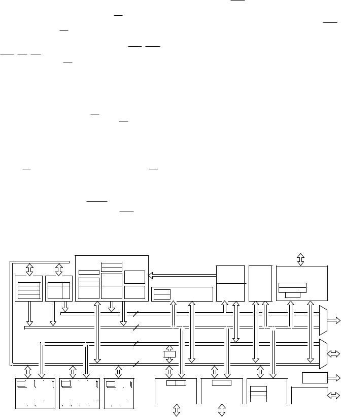
ADSP-2171/ADSP-2172/ADSP-2173
Bus Request & Bus Grant
The ADSP-217x can relinquish control of the data and address buses to an external device. When the external device requires access to memory, it asserts the bus request (BR) signal. If the ADSP-217x is not performing an external memory access, then it responds to the active BR input in the following processor cycle by:
∙three-stating the data and address buses and the PMS, DMS, BMS, RD, WR output drivers,
∙asserting the bus grant (BG) signal, and
∙halting program execution.
If the Go Mode is enabled, the ADSP-217x will not halt program execution until it encounters an instruction that requires an external memory access.
If the ADSP-217x is performing an external memory access when the external device asserts the BR signal, then it will not three-state the memory interfaces or assert the BG signal until the processor cycle after the access completes, which can be up to eight cycles later depending on the number of wait states. The instruction does not need to be completed when the bus is granted. If a single instruction requires two external memory accesses, the bus will be granted between the two accesses.
When the BR signal is released, the processor releases the BG signal, reenables the output drivers and continues program execution from the point where it stopped.
The bus request feature operates at all times, including when the processor is booting and when RESET is active.
The new Bus Grant Hang logic and associated BGH pin allow the ADSP-217x to operate in a multiprocessor environment with a minimal number of “wasted” processor cycles. The bus grant hang pin is asserted when the ADSP-217x desires a cycle,
but cannot execute it because the bus is granted to some other processor. With the BGH signal, the other processor(s) in the system can be alerted that the ADSP-217x is hung and release the bus by deasserting bus request. Once the bus is released the ADSP-217x executes the external access and deasserts BGH.
This is a signal to the other processors that external memory is now available.
ADSP-217X REGISTERS
Figure 7 summarizes all the registers in the ADSP-217x. Some registers store values. For example, AX0 stores an ALU operand; I4 stores a DAG2 pointer. Other registers consist of control bits and fields, or status flags. For example, ASTAT contains status flags from arithmetic operations, and fields in DWAIT control the numbers of wait states for different zones of data memory.
A secondary set of registers in all computational units allows a single-cycle context switch.
The bit and field definitions for control and status registers are given in the rest of this section, except for IMASK, ICNTL and IFC, which are defined earlier in this data sheet. The system control register, DWAIT register, timer registers, HIP control registers, HIP data registers, and SPORT control registers are all mapped into data memory; that is, registers are accessed by reading and writing data memory locations rather than register names. The particular data memory address is shown with each memory-mapped register.
Register bit values shown on the following pages are the default bit values after reset. If no values are shown, the bits are indeterminate at reset. Reserved bits are shown in gray; these bits should always be written with zeros.
|
|
|
|
|
|
|
PROGRAM SEQUENCER |
|
|
|
|
|
|
|
||
|
|
|
|
|
|
|
|
ICNTL |
|
|
|
|
|
|
|
|
|
|
|
|
|
|
|
SSTAT |
IFC |
LOOP |
|
|
PROGRAM |
|
HOST |
|
|
|
|
|
|
|
|
|
IMASK |
|
|
|
ROM |
|
INTERFACE |
|||
|
|
|
|
|
|
|
|
|
|
|
|
|||||
|
|
|
|
|
|
|
|
STACK |
|
|
|
|
||||
DAG 1 |
DAG 2 |
|
CNTR |
MSTAT |
|
|
|
8K X 24 |
DATA |
PORT |
|
|||||
|
4 X 18 |
|
|
|
|
|||||||||||
I0 |
M0 |
L0 |
I4 |
M4 |
L4 |
|
OWRCNTR |
ASTAT |
|
|
|
PROGRAM |
SRAM |
0x3FE0-0x3FE5 |
DATA |
|
I1 |
M1 |
L1 |
I5 |
M5 |
L5 |
|
COUNT |
STATUS |
PC |
|
SYSTEM CONTROL |
2K X 16 |
0x3FE6-0x3FE7 |
STATUS |
||
|
0x3FFF |
|
SRAM |
|||||||||||||
I2 |
M2 |
L2 |
I6 |
M6 |
L6 |
|
STACK |
STACK |
STACK |
|
|
0x3FE8 |
HMASK |
|||
I3 |
M3 |
L3 |
I7 |
M7 |
L7 |
|
4 X 14 |
12 X 25 |
16 X 14 |
0x3FFE |
DM WAIT CONTROL |
|
2K X 24 |
|
||
|
|
|
|
|
|
|||||||||||
|
|
|
|
|
|
|
|
|
14 |
PMA BUS |
|
|
|
|
|
|
|
|
|
|
|
|
|
|
|
14 |
DMA BUS |
|
|
|
|
|
|
|
|
|
|
|
|
|
|
|
24 |
PMD BUS |
|
|
|
|
|
|
|
|
|
|
|
|
|
|
|
|
PX |
|
|
|
|
|
|
|
|
|
|
|
|
|
|
|
16 |
DMD BUS |
|
|
|
|
|
|
|
|
|
|
|
|
|
|
|
|
|
|
|
|
TIMER |
|
FLAGS |
AX0 |
AX1 |
AY0 |
AY1 |
|
MX0 |
MX1 |
MY0 MY1 |
SI SE |
SB |
|
RX0 TX0 |
RX1 |
TX1 |
|
|
|
|
|
|
|
|
|
|
|
|
|
|
|
|
|
|
0x3FFA-0x3FF3 |
|
|
|
0x3FF2-0x3FEF |
|
|
|
0x3FFD |
TPERIOD |
POWERDOWN |
|
||||
ALU |
|
|
MAC |
SHIFTER |
|
CONTROL REGISTERS |
CONTROL REGISTERS |
|
|
0x3FFC |
TCOUNT |
CONTROL |
|
|||||||||||||||||
|
|
|
|
|
|
|
|
|
|
|
|
|
|
|
|
0x3FFB |
TSCALE |
|
||||||||||||
|
|
|
|
|
|
|
|
|
|
|
|
|
|
|
SPORT 0 |
|
SPORT 1 |
|
|
LOGIC |
|
|
||||||||
AR |
|
AF |
|
MR0 |
|
MR1 |
MR2 |
MF |
|
|
SR0 |
SR1 |
|
|
|
|
|
|
|
|
|
|
|
|
|
|
|
|
|
|
|
|
|
|
|
|
|
|
|
|
|
|
|
|
|
|
|
|
|
|
|
|
|
|
|
|
|
|
|
|
|
Figure 7. ADSP-217x Registers Control Register
–10– |
REV. A |