

a
 R DSP
R DSP
|
|
|
|
ADSP-2141L |
|
|
|
|
|
|
|
APPLICATIONS |
|
|
SECURE KERNEL CONTROL |
||
Security Coprocessor for High Speed Networking Prod- |
Tamper-Resistant Isolation of Cryptographic Functions |
||||
ucts (Routers, Switches, Hubs) |
Enforces Security Perimeter Around Crypto Functions |
||||
Cryptographic Core for Firewalls, Hardware Encryptors, |
and Crypto Storage Locations |
||||
and More |
|
|
Anticloning Protection |
||
Crypto Peripheral for Implementing Secure NIC Adapt- |
Secure Algorithm Download |
||||
ers (10/100 Ethernet, Token Ring, ISDN) |
SafeNet CGX LIBRARY |
||||
Secure Modem-on-a-Chip (V.34, ADSL) |
|||||
On-Chip SafeNet CGX Crypto Library with Flexible CGX |
|||||
|
|
|
|
||
FEATURES |
|
|
API |
||
DES CRYPTO BLOCK |
|
|
Includes Chained and Parallel Execution Commands |
||
640 Mbps Sustained Performance—Single DES |
Such as Hash-and-Encrypt |
||||
214 Mbps Sustained Performance—Triple DES |
Embodied as 32K Words (32K 3 24) Kernel Program |
||||
Supports All Modes: ECB; CBC; 64-Bit OFB; and 1-, 8-, |
Mask-Programmed into On-Chip ROM |
||||
64-Bit CFB. Includes Automatic Padding |
On-Chip Protected 4K 3 16 Security Scratchpad RAM |
||||
Implements IPsec ESP Transforms Autonomously at |
RANDOM NUMBER GENERATOR |
||||
OC-3 (155 Mbps) Rates (3-DES, SHA-1) |
|||||
Hardware-Based Nondeterministic Random Number |
|||||
|
|
|
|
||
HASH BLOCK |
|
|
Generator |
||
Hardware-Based SHA-1 and MD-5 Hashing |
Generates Internal Session Keys That Are Never |
||||
253 Mbps Sustained Performance—SHA-1 |
Exposed Outside of the SafeNet DSP |
||||
315 Mbps Sustained Performance—MD-5 |
Redundant Fail-Safe Design |
||||
Implements IPsec AH and HMAC Transforms |
Up to 1.3 Mbits of Random Data Available per Second |
||||
|
|
|
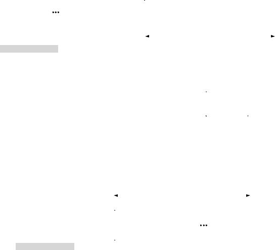
FUNCTIONAL BLOCK DIAGRAM |
||
|
|
|
|
|
|
|
KERNEL |
BUS_MODE |
|
||
|
MODE |
|
|||
|
|
|
|
||
|
CONTROL |
|
|
|
|
|
|
|
|
|
|
|
|
IDMA MODE |
|
|
16 |
IDMA |
16 |
16- |
|
|
|
IDMA |
|
|
|
|
INTERFACE |
|
OR |
INTERRUPTS |
|
BUS |
|
|
|
|
|
|
32-BIT |
ADSP-218x |
|
|
|
|
|
|
|
BUS |
|
|
|
|
|
|
|
|
|
||
|
PCI MODE |
DMA-32 |
|
|
|
|
|
||
|
DSP CORE |
|
|
|
|
|
|||
FLAGS |
|
|
CONTROLLER |
|
|
|
|
||
|
|
|
|
|
|
|
|||
|
|
|
|
|
|
32 |
PCI OR |
32 |
|
|
|
|
|
|
|
|
CARDBUS |
|
|
|
KERNEL ROM |
PROTECTED |
|
|
|
|
INTERFACE |
|
|
SPORT 0 |
ENCRYPT |
HASH |
|
|
|
|
|
||
32K 3 24 |
KERNEL |
RNG |
PUBLIC KEY |
|
|
|
|||
|
|
RAM |
BLOCK |
BLOCK |
BLOCK |
ACCELERATOR |
|
|
|
SERIAL |
|
(DES, 3-DES) |
(MD-5, SHA-1) |
|
|
|
|||
PROG ROM |
(4K 3 16) |
|
|
|
|
|
|||
PORTS |
|
|
|
|
|
BUS_MODE |
|
||
16K 3 24 |
|
|
|
|
|
|
|||
|
|
|
|
|
EMI BUS |
|
|||
SPORT 1 |
|
|
|
|
|
|
|
|
|
DATA ROM |
|
|
|
|
|
BUS_SEL |
|
||
|
INTERRUPT |
APPLICATION |
EXTERNAL |
LASER |
SERIAL |
|
|||
|
|
|
|
||||||
|
16K 3 16 |
MEMORY |
VARIABLE |
EEPROM |
|
|
|
||
|
CONTROLLER |
REGISTERS |
|
|
|
||||
|
|
INTERFACE |
STORE |
INTERFACE |
|
|
|
||
|
|
|
|
|
|
|
|||
TIMER |
26-BITS |
32-BITS |
|
ADDR |
DATA |
|
PF7/INT_H
RAM/ROM
SafeNet is a registered trademark of Information Resource Engineering (IRE).
REV. 0
Information furnished by Analog Devices is believed to be accurate and reliable. However, no responsibility is assumed by Analog Devices for its use, nor for any infringements of patents or other rights of third parties which may result from its use. No license is granted by implication or otherwise under any patent or patent rights of Analog Devices.
One Technology Way, P.O. Box 9106, Norwood, MA 02062-9106, U.S.A.
Tel: 781/329-4700 |
World Wide Web Site: http://www.analog.com |
Fax: 781/326-8703 |
© Analog Devices, Inc., 2000 |
ADSP-2141L
PUBLIC KEY ACCELERATOR
Accelerator for Math-Intensive Public Key Operations Diffie-Hellman Negotiate: <29 ms (1024-Bit Modulus,
180-Bit Exponent)
RSA 1024-Bit Sign: <29 ms; RSA 1024-Bit Verify: 6 ms DSA Sign: <39 ms; DSA Verify: <66 ms
KEY MANAGEMENT BLOCK
Laser-Programmed Unique Triple-DES Cryptovariable Protects Off-Chip Storage
Support for Secure Storage of Both Secret Keys and Public/Private Key Pairs
Trust-Model Rules Enforcement
Only Encrypted Keys May Be Exported Off the Chip Internal Key Cache for 15 Keys—Can Be Expanded to
700 Keys On-Chip
Keys May Also Be Securely Stored Off-Chip, Allowing Unlimited Storage
DSP CORE
40 MIPS Sustained Performance Single-Cycle Instruction Execution Single-Cycle Context Switch Zero-Overhead Looping
Low Power Dissipation
16K Words (16K 3 24) On-Chip Program RAM 16K Words (16K 3 16) On-Chip Data RAM
64M Words Off-Chip Program and Data Memory Programmable 16-Bit Interval Timer with Prescale
PCI BUS/CARDBUS INTERFACE 32-Bit 3.3 V Bus Interface
33 MHz or 40 MHz* Bus Speed Bus Master and Target Modes
Can Directly DMA Between Crypto Functions and Other PCI Bus Agents
*66 MHz speed pending chip characterization.
GENERAL DESCRIPTION
The ADSP-2141L SafeNet DSP is a highly integrated embedded security processor that incorporates a sophisticated, general purpose DSP, along with a number of high performance Cryptographic function blocks, as well as PCI, DMA and Serial EEPROM interfaces. It is fabricated in 0.35 CMOS triplelayer metal technology and uses a 3.3 V power supply. It is available in a 208-lead MQFP package with a commercial (0°C to 70°C) temperature range.
DSP Core
The DSP is a standard Analog Devices ADSP-218x core with full ADSP-2100 family compatibility. The ADSP-218x Core combines the base DSP components from the ADSP-2100 family with the addition of two serial ports, a 16-bit internal DMA port, a byte DMA port, a programmable timer, Flag I/O, extensive interrupt capabilities, and on-chip program and data memory. The external memory interface of the 218x core has been extended to support up to 64M-words addressing for both program and data memory. Some core enhancements have been added in the ADSP-2141L, including on-chip security ROM and interrupt functions. Refer to the Analog Devices ADSP-2183 data sheet for further information.
SafeNet CGX Library–Secure Kernel
The SafeNet CGX Library is a crypto library embodied as firmware (a secure kernel) that is mask-programmed into ROM within the DSP. This solution protects the library from tampering. The CGX Library provides the Application Programming Interface (API) to applications that require security services from the ADSP-2141L. Those applications may be software executing in user mode on the DSP, or they may be external host software accessing the ADSP-2141L via a PCI bus. Approximately 40 Crypto commands—called CGX (CryptoGraphic eXtensions)— are provided at the API and a simple control block structure is used to pass arguments into the secure kernel and return status. The CGX library includes integrated drivers for the various hardware crypto blocks on the chip. This allows the programmer to ignore those details and concentrate on other product design issues.
The CGX library firmware runs under a protected mode state of the DSP as described in the Kernel Mode Control section following. This guarantees the security integrity of the system during the execution of CGX processes and, for example, prevents disclosure of cryptographic key data or tampering with a security operation.
Kernel Mode Control
The Kernel Mode Control subsystem is responsible for enforcing the security perimeter around the cryptographic functions of the ADSP-2141L. The device may operate in either user mode (kernel space is not accessible) or kernel mode (kernel space is accessible) at a given time. When in kernel mode, the kernel RAM and certain protected crypto registers and functions (kernel space) are accessible only to the CGX library firmware. The CGX Library executes host-requested macro-level functions and then returns control to the calling application. The kernel mode control subsystem resets the DSP should any security violation occur, such as attempting to access a protected memory location while in user mode.
–2– |
REV. 0 |

ADSP-2141L
Protected Kernel RAM
The 4K × 16 kernel RAM provides a secure storage area on the ADSP-2141L for sensitive data such as keys or intermediate calculations during public key operations. The Kernel Mode Control subsystem (above) enforces the protection by allowing only internal secure kernel mode access to this RAM. A public keyset and a cache of up to 15 secret keys may be stored in kernel RAM. Secure key storage may be expanded to 700 secret keys by assigning segments of the DSP’s internal data RAM to be protected. Furthermore, a virtually unlimited number of data encryption keys may be stored in an encrypted form in off-chip memory.
Encrypt Block
The encrypt block performs high speed DES and Triple-DES encrypt/decrypt operations. All four standard modes of DES are supported: Electronic Code Book (ECB), Cipher Block Chaining (CBC), 64-bit Output Feedback (OFB) and 1-bit, 8-bit and 64bit Cipher Feedback (CFB). The DES encrypt/decrypt operations are highly pipelined and execute full 16-round DES in only four clock cycles. Hardware support for padding insertion, verification and removal further accelerates the encryption operation. Context switching is provided to minimize the overhead of changing crypto keys and Initialization Vectors (IVs) to nearly zero.
Hash Block
The secure hash block is tightly coupled with the encrypt block and provides hardware accelerated one-way hash functions. Both the MD-5 and SHA-1 algorithms are supported. Combined operations that chain both hashing and encrypt/decrypt functions are provided in order to significantly reduce the processing time for data that needs both operations applied. For hash-then-encrypt and hash-then-decrypt operations, the ADSP-2141L can perform parallel execution of both functions from the same source and destination buffers. For encrypt-then-hash and decrypt-then-hash operations, the processing must be sequential, but minimum latency is still provided through the pipeline chaining design. An offset may be specified between the start of hashing and the start of encryption to support certain protocols such as IPsec. A ‘mutable bit handler’ is also provided on the hash engine to facilitate IPsec AH processing.
Random Number Generator (RNG) Block
The hardware random number generator provides a true, nondeterministic noise source for the purpose of generating keys, Initialization Vectors (IVs), and other random number requirements. Random numbers are provided as 16-bit words to the kernel. The CGX kernel requests random numbers as needed to perform requested CGX commands such as CGX_Gen_Key, and can also directly supply from 1 to 65,535 random bytes to a host application via the CGX_Random command.
Public Key Accelerator
The public key accelerator module works in concert with the CGX kernel firmware to provide full public key services to the host application. The kernel provides macro-level functions to perform Diffie-Hellman key agreement, RSA encrypt or decrypt, DSA compute and verify digital signatures. The hardware accelerator block speeds computation-intensive operations such as large vector multiply, add, subtract, square.
PCI/Cardbus Interface
A full 40 MHz/33 MHz PCI bus interface has been added to the core DSP functions. The 32-bit PCI interface supports both bus master and target modes. The ADSP-2141L is capable of using DMA to directly access data on other PCI entities and pass that data through its encryption/hash engines.
32-Bit DMA Controller
The ADSP-2141L incorporates a high performance 32-bit DMA controller which can be set up to move data efficiently between Host PCI memory, the hash/encrypt blocks, and/or external memory. The DMA controller can be used with the PCI bus in master mode, thus autonomously moving 32-bit data with minimal DSP intervention. Up to 255 long words (1020 bytes) can be moved in a burst at up to 160 Mbytes per second.
Application Registers
The application registers are a set of memory-mapped registers that facilitate communications between the ADSP-2141L and a host processor via the PCI bus. One of the registers is a mailbox that is 44 bytes long and set up to hold the CGX command structure passed between the host and DSP processors. The application registers also provide the mechanism that allows the DSP and the external host to negotiate ownership of the hash/ encrypt block.
Serial EEPROM Interface
The serial EEPROM interface allows an external nonvolatile memory to be connected to the ADSP-2141L for storing PCI configuration information (Plug and Play), as well as generalpurpose nonvolatile storage. For example, encrypted (black) keys could be stored into EEPROM for fast recovery after a power outage.
Interrupt Controller
The DSP core provides support for 14 interrupt sources, including six external and eight internal. All interrupts are prioritized into 12 levels and interrupt nesting may be enabled or disabled under software control. The security block interrupt controller provides enhancements to the DSP interrupt functions.
Primarily, the interrupt controller provides a new interrupt generation capability to the DSP or to an external host processor. Under programmable configuration control, a crypto interrupt may be generated due to completion of certain operations such
as encrypt complete, hash complete. The interrupt may either be directed at the DSP core (on IRQ2), or provided on an out-
put line (PF7/INT_H) to a host subsystem.
Laser Variable Storage
The laser variable storage consists of 256 bits of tamper-proof factory-programmed data that is only accessible to the internal function blocks and the security kernel. Included in these laser variable bits are:
•Local Storage Variable (master key-encryption key)
•Randomizer Seed (to supplement the true entropy fed into the RNG)
•Program Control Data (enables/disables various features and configures the ADSP-2141L)
•CRC of the Laser Data (to verify laser data integrity).
REV. 0 |
–3– |
ADSP-2141L
The Program Control Data Bits (PCDBs) include configuration for permitted key lengths, algorithm enables, Red KEK loading. Most of the PCDB settings may be overridden with a digitally signed token which may be loaded into the ADSP-2141L when it boots. These tokens are created by IRE and each is targeted to a specific ADSP-2141L using a hash of its unique identity.
Downloadable Secure Code
The ADSP-2141L allows additional security functions to be added to the device through a secure download feature. Up to 16K words of code may be downloaded into internal memory within the DSP and this code can be given the security privileges of the CGX kernel firmware. All downloaded firmware is authenticated with a digital signature and verified with an on-chip public key. Additional functions could include new encryption, hash or public key algorithms such as IDEA, RC-4, RIPEMD, elliptic curve, or any other application that needs direct control over the protected cryptographic hardware.
ARCHITECTURE OVERVIEW
This section provides an architecture-level description of the unique function blocks within the ADSP-2141L.
Memory Map
The ADSP-2141L memory map is very similar to that of the ADSP-2183 DSP, except that it includes significantly more offchip memory addressing, and has additional crypto registers which are accessible to the user.
DSP Core
The DSP core is architecturally identical to the ADSP-218x with a few exceptions.
•The memory map includes additional external memory addressing through the PMOVLAY and DMOVLAY mechanisms. For more information, see the Memory Map section.
•Additional memory-mapped crypto registers are available in the kernel data RAM space.
•The PF7/INT_H flag pin may be reassigned to be the host interrupt output.
0x3FFF |
8K KERNEL TOP |
|
|
8K KERNEL BASE |
8K INTERNAL |
|
8K EXTERNAL |
8K EXTERNAL |
|
8K KERNEL |
||||
|
|
|
|
|
|
|||||||||
|
|
KERNEL MODE |
|
|
KERNEL MODE |
PAGE |
|
PAGE = 0 |
PAGE 1 |
|
PAGE 8191 |
|||
|
|
(PMOVLAYL = C) |
|
|
(PMOVLAYL = F) |
(PMOVLAYL = 0) |
|
(PMOVLAYL = 1) |
(PMOVLAYL = 2) |
|
(PMOVLAYL = 2) |
|||
0x2000 |
(PMOVLAYH = 000) |
|
|
(PMOVLAYH = 000) |
(PMOVLAYH = 000) |
(PMOVLAYH = 000) |
(PMOVLAYH = 000) |
|
(PMOVLAYH = FFF) |
|||||
|
|
|
|
|
|
|
|
|
|
|
|
|
||
|
|
|
|
|
|
|
|
|
|
|
|
|
|
|
|
|
|
|
|
0x1FFF |
|
|
|
|
UP TO 64 MEGAWORDS |
|
|
|
|
PMOVLAYL = LS NIBBLE OF PMOVLAY |
8K INTERNAL |
|
|
|
|
|
|
|||||||
|
|
EXTERNAL PROGRAM MEMORY |
|
|
||||||||||
(COMMON BANK) |
|
|
|
|
||||||||||
PMOVLAYH = MS 3 NIBBLES OF PMOVLAY |
|
|
|
|||||||||||
|
|
(PMOVLAYL ALTERNATES 2, 1, 2, 1...) |
||||||||||||
|
|
|
||||||||||||
|
|
|
|
|
0x0000 |
|
|
|
|
|
|
|
|
|
|
SHADED = KERNEL SPACE |
|
|
|
|
|
|
|
|
|
|
|||
|
|
|
|
|
|
|
|
|
|
|
|
|||
|
|
|
|
|
|
|
|
|
|
|||||
|
|
|
|
|
|
|
|
|
|
|
|
|
|
|
Figure 1. Program Memory (MMAP = 0)
|
0x3FFF |
|
8K KERNEL TOP |
|
8K KERNEL |
|
|
|
8K KERNEL |
|
8K KERNEL |
|
8K INTERNAL |
|
|||||||||
|
|
|
|
|
|
|
|
|
|
|
|||||||||||||
|
|
|
|
KERNEL MODE |
|
KERNEL MODE |
|
KERNEL MODE |
|
KERNEL MODE |
|
|
|||||||||||
|
|
|
|
|
|
|
|
(PMOVLAYL = 0) |
|
||||||||||||||
|
|
|
|
(PMOVLAYL = C) |
(PMOVLAYL = D) |
|
(PMOVLAYL = E) |
|
(PMOVLAYL = F) |
|
|
||||||||||||
|
|
|
|
|
|
(PMOVLAYH = 000) |
|
||||||||||||||||
|
0x2000 |
|
(PMOVLAYH = 000) |
(PMOVLAYH = 000) |
(PMOVLAYH = 000) |
(PMOVLAYH = 000) |
|
||||||||||||||||
|
|
|
|
|
|
|
|||||||||||||||||
|
|
|
|
|
|
|
|
|
|
|
|
|
|
|
|
|
|
|
|
|
|
||
|
|
|
|
|
|
|
|
|
|
|
|
|
|
|
|
|
|
|
|
|
|
|
|
|
PMOVLAYL = LS NIBBLE OF PMOVLAY |
|
|
|
|
|
|
|
0x1FFF |
|
|
|
|
|
|||||||||
|
|
|
|
|
|
|
|
|
|
|
8K EXTERNAL |
|
|||||||||||
|
PMOVLAYH = MS 3 NIBBLES OF PMOVLAY |
|
|
|
|
|
|
|
|
|
|
|
|||||||||||
|
|
|
|
|
|
|
|
|
|
|
|
|
|
|
|
|
|
|
|
||||
|
|
SHADED = KERNEL SPACE |
|
|
|
|
|
|
|
|
0x0000 |
|
|
|
|
|
|||||||
|
|
|
|
|
|
|
Figure 2. Program Memory (MMAP = 1) |
|
|
|
|
|
|||||||||||
|
|
|
|
0x3FFF |
|
|
|
|
|
|
|
|
|
|
|
|
|
|
|
|
|
|
|
|
|
|
|
|
|
|
32 |
|
|
|
|
|
|
|
|
|
|
|
|
|
|
||
|
|
|
|
|
|
|
MEMORY-MAPPED |
|
|
|
|
|
|
|
|
|
|
|
|
|
|
||
|
|
|
|
0x3FE0 |
|
|
|
REGISTERS |
|
|
|
|
|
|
UP TO 64 MEGAWORDS |
|
|
|
|
|
|||
|
|
|
|
|
|
|
|
|
|
|
|
|
|
|
|
|
|
|
|
||||
|
|
|
|
0x3FDF |
|
|
|
8160 WORDS |
|
|
|
|
|
EXTERNAL DATA MEMORY |
|
|
|||||||
|
|
|
|
|
|
|
|
|
|
|
|
|
|||||||||||
|
|
|
|
|
|
|
|
|
|
|
|
(DMOVLAYL ALTERNATES 2, 1, 2, 1...) |
|||||||||||
|
|
|
|
|
|
|
|
INTERNAL |
|
|
|
|
|||||||||||
|
|
|
|
0x2000 |
|
|
|
|
|
|
|
|
|
|
|
|
|
|
|
|
|
||
|
|
|
|
|
|
|
|
|
|
|
|
|
|
|
|
|
|
|
|
|
|
|
|
0x1FFF |
MEMORY-MAPPED |
|
|
|
|
|
|
|
|
|
|
|
|
|
|
|
|
|
|
|
|||
0x1800 |
|
|
REGISTERS |
|
|
|
8K INTERNAL |
|
|
|
8K EXTERNAL |
|
8K EXTERNAL |
|
|
8K KERNEL |
|||||||
0x17FF |
|
|
PROTECTED |
|
|
|
|
|
|
PAGE = 0 |
|
|
PAGE 1 |
|
|
PAGE 8191 |
|||||||
|
|
|
|
(DMOVLAYL = 0) |
|
|
|
|
|
|
|
||||||||||||
0x1000 |
4K KERNEL RAM |
|
|
|
|
(DMOVLAYL = 1) |
|
(DMOVLAYL = 2) |
|
|
(DMOVLAYL = 2) |
||||||||||||
|
|
(DMOVLAYH = 000) |
|
|
|
|
|
||||||||||||||||
0x0FFF |
(DMOVLAY = 000F) |
|
|
(DMOVLAYH = 000) |
(DMOVLAYH = 000) |
|
|
(DMOVLAYH = FFF) |
|||||||||||||||
|
|
|
|
|
|
|
|||||||||||||||||
0x0000 |
|
KERNEL MODE |
|
|
|
|
|
|
|
|
|
|
|
|
|
|
|
|
|
|
|
||
|
|
|
|
|
|
|
|
|
|
|
|
|
|
|
|
|
|
|
|
||||
|
SHADED = KERNEL SPACE |
|
|
|
|
|
|
|
|
|
|
|
|
|
|
|
|
|
|
||||
|
|
|
|
|
|
|
|
|
|
|
|
|
|
|
|
|
|
|
|
|
|
|
|
Figure 3. Data Memory
–4– |
REV. 0 |
ADSP-2141L
•IRQ2 now can include interrupt sources from the crypto subsystem, depending on interrupt mask registers.
•A new read register has been added to indicate the state of interrupt enable and interrupt masks.
•The kernel mode control subsystem has been added to supervise the protected mode of operation of the DSP core.
•Internal RAM protection logic has been added to allow the kernel to seize increments of 1K word of internal PRAM and DRAM.
•Bus mode configuration (218x vs. PCI) pins have been added.
•32K words of kernel program ROM have been added to the DSP memory space. (See the Memory Map section.)
Kernel Mode Control
The kernel mode control subsystem provides the following functions which serve to enforce the security integrity of the ADSP-2141L:
•Provide a means to securely enter the kernel mode.
•Provide a means to properly exit the kernel mode.
•Prevent user mode access to protected memory and register locations.
•Manage interrupts during kernel mode executions.
•Manage the reset function to ensure that sensitive variables in DSP registers are erased.
Most of the kernel mode control functions are implemented in the hardware of the ADSP-2141L and are not directly visible to nonkernel applications (user mode). Any attempt by a user mode application program running on the DSP to access a kernel space addresses (PRAM 0x2001 – 0x3FFF, PMOVLAY 000C – 000F; or DRAM 0x0000 – 0x17FF, DMOVLAY 000F) results in an immediate chip reset and all sensitive registers and memory locations are erased. Kernel mode may only be entered via a call, jump or increment to address 0x2000 with PMOVLAY
set to 0x000F. Once in kernel mode, any branch to nonkernel space program memory causes the DSP to return to user mode. (Note: For security reasons when in kernel mode, the DSP does not respond to Emulator bus requests.)
The kernel mode can be interrupted during execution; however, during certain periods where sensitive data is being moved, all interrupts are disabled. Within the interrupt service routine, another call to the kernel (CGX call) may be made if desired, although there are limitations on which CGX commands may preempt another. (For information, see the ADSP-2141L CGX Interface Programmer’s Guide http://www.ire-ma.com/proddoc.htm.) Only one level of kernel mode nesting is permitted. An interrupt to a user mode vector location while in nested kernel mode will also trigger the violation reset logic.
Once the interrupt service routine is finished, the return-from- interrupt must return control back to the kernel at the address/ overlay that was originally interrupted, otherwise the protection logic will issue a chip reset.
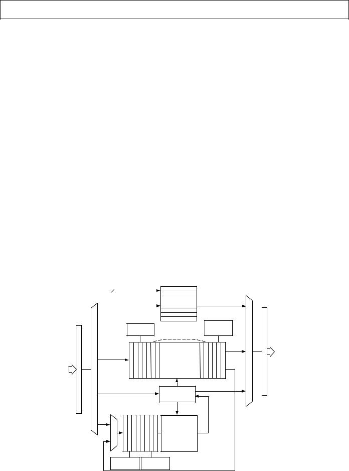
Hash and Encrypt Block Overview
The encrypt block is tightly coupled to the hash block in the ADSP-2141L and therefore the two are discussed together. Refer to Figure 4, Hash/Encrypt Functional Block Diagram, for the following description.
The algorithms implemented in the combined hash and encryption block are: DES, Triple DES, MD-5 and SHA-1. Data can be transferred to and from the module once to perform both hashing and encryption on the same data stream. The DES encrypt/decrypt operations are highly paralleled and pipelined, and execute full 16-round DES in only four clock cycles. The internal data flow and buffering allows parallel execution of hashing and encryption where possible, and allows processing of data concurrently with I/O of previous and subsequent blocks.
REGISTER |
7 |
ADDRESS |
|
WR |
|
|
RD |
|
|
|
|
PAD |
|
PAD |
|
CONSUME |
||
INSERTION |
512-BIT |
AND VERIFY |
||
|
|
FIFO |
|
|
|
|
|
DSP |
|
|
|
|
OR |
|
|
|
ENCRYPT/ |
PCI |
|
DSP |
|
DECRYPT |
|
|
|
BLOCK |
|
||
OR |
|
|
|
|
PCI |
|
|
|
|
WRITE |
|
READ |
||
|
CONTEXT |
|||
CONTEXT |
CONTEXT |
|||
|
||||
|
|
|
||
|
STORAGE (0/1) |
16-/32-BIT |
||
|
|
|
||
512-BIT |
|
OUTPUT |
||
|
BUS |
|||
FIFO |
|
|
||
|
|
HASH |
||
|
|
|
||
16-/32-BIT |
|
|
DIGEST |
|
INPUT |
|
|
|
|
BUS |
|
|
|
|
|
|
HASH |
|
|
|
|
BLOCK |
|
|
MUTABLE BIT |
PAD |
(ENCRYPT-THEN-HASH) |
||
PROCESSING |
INSERTION |
(DECRYPT-THEN-HASH) |
||
Figure 4. Hash/Encrypt Functional Block Diagram
REV. 0 |
–5– |
ADSP-2141L
Context switching is optimized to minimize the overhead of changing cryptographic keys to near zero.
The software interface to the module consists of a set of memory-mapped registers, all of which are visible to the DSP and most of which can be enabled for host access via the PCI bus. A set of five, 16-bit registers define the operation to be performed, the length of the data buffer to be processed, in bytes, the offset between the start of hashing and encryption (or vice versa), and the padding operation. If the data length is unknown at the time the encrypt/decrypt operation is started, the data length register may be set to zero, which specifies special handling. In this case, data may be passed to the hash/encrypt block indefinitely until the end of data is encountered. At that time, the operation is terminated by writing a new control word to the hash/encrypt control register (either to process the next packet or to invoke the idle state if there is no further work to do). This will close out the processing for the packet, including the addition of the selected crypto padding.
A set of seven status registers provides information on when a new operation can be started, when there is space available to accept new data, when there is data available to be read out, and the results from the padding operation.
Crypto Contexts
There are two sets of crypto-context registers. Each context contains a DES or triple DES key, initialization vector, and precomputed hashes (inner and outer) of the authentication key for HMAC operations. The contexts also contain registers to reload the byte count from a previous operation (which is part of the hashing context), as well as an IV (also called salt) for decrypting a black key, if necessary.
Once a crypto-context has been loaded and the operation defined, data is processed by writing it to a data input FIFO. At the I/O interface, data is always written to, or read from, the same address. Internally, the hash and encryption functions have separate 512-bit FIFOs, each with their own FIFO management pointers. Incoming data is automatically routed to one or both of these FIFOs, depending on the operation in progress. Output from the encryption block is read from the data output FIFO. In encrypt-hash or decrypt-hash operations, the data is also automatically passed to the hashing data input FIFO. Output from the hash function is always read from the digest register of the appropriate crypto-context.
The initialization vector to be used for a crypto operation can be loaded as part of a crypto-context. When an operation is complete, the same context will contain the resulting IV produced at the end, which can be saved away and restored later to continue the operation with more data.
In certain packet-based applications such as IPsec, a feature is available that avoids the need for the control software to generate and load random IVs for outgoing (encrypted) packets. Effectively, the IV register can be configured to be automatically updated with new random numbers for each encrypted packet, with almost no software intervention.
Padding
When the input data is not a multiple of eight bytes (a 64-bit DES block), the encrypt module can be configured to automatically append pad bytes. There are several options for how the padding is constructed, which are specified using the pad control word of the operation description. Options include zero padding, pad-length character padding (PKCS#7), incrementing count,
with trailing pad length and next header byte (for IPsec), or fixed character padding. Note that for the IPsec and PKCS#7 pad protocols, there are cases where the padding not only fills out the last 8-byte block, but also causes an additional 8-byte block of padding to be added.
For the hash operations, padding is automatically added as specified in the MD-5 and SHA-1 standards. When the hash final command is issued indicating the last of the input data, the algorithm-specified padding and data count bits are added to the end of the hash input buffer prior to computing the hash.
Data Offsets
Certain security protocols, including IPsec, require portions of a data packet to be hashed while the remainder of the data is both hashed and encrypted. The ADSP-2141L supports this requirement through the OFFSET register, which allows specifying the number of 32-bit dwords of offset between the hash and encrypt/ decrypt operations.
Black Key Loads
The cryptographic keys loaded as part of a crypto-context can be stored off-chip in a black, or encrypted, form. If the appropriate control bit is set (HECNTL Bit 15), the DES or 3-DES key will be decrypted immediately after it is written into the context register. The hardware handles this decryption automatically. The Key Encryption Key (KEK) that covers the black keys
is loaded in a dedicated write-only KEK register within the ADSP-2141L. The IV for decrypting the black secret key is called ‘salt’ and must be stored along with the black key (as part of the context). Note that 3-DES CBC mode is used for protecting 3-DES black keys and single DES CBC is used for single DES black keys.
When black keys are used, the key-decrypt operation adds a 6-cycle overhead (0.15 s @ 40 MHz) for DES keys or 36-cycle overhead (0.9 s @ 40 MHz) for triple DES keys each time a new crypto-context is loaded. (Note that if the same context is used for more than one packet operation, the key decryption does not need to be performed again.) Depending on the sequencing of operations, this key decryption may in fact be hidden (from a performance impact perspective) if other operations are underway. This is because the black key decryption process only requires that the DES hardware be available. For example, if the DSP is reading the previous hash result from the output FIFO, the black key decryption can be going on in parallel. Also note that the data driver firmware does NOT have to wait for the key to be decrypted before writing data to the input FIFO. The hardware automatically waits for the key to be decrypted before beginning to process data for a given packet. So, with efficient pipeline programming, it is possible to make the impact of black key essentially zero.
The KEK for key decryption is loaded via the secure kernel firmware using one of the CGX key manipulation commands. (For more information, see the Command Summary section.)
This KEK is typically the same for all black keys, since it is usually protecting local storage only. It is designated the DKEK in the CGX API.
One of the laser-programmed configuration bits specifies whether red (plaintext) keys are allowed to be loaded into the ADSP2141L from a host. If the AllowRedKeyLoad laser bit is not set, keys may only be loaded in their black form. This is useful in systems where export restrictions limit the key length that may be used or where the external storage environment is untrusted.
–6– |
REV. 0 |

ADSP-2141L
If the AllowRedKeyLoad bit is set, keys may be loaded either in their black form, or in the red or unencrypted form. Note that the laser configuration bit may be overridden with a signed enabler token. (For more information, see the Laser Variable Storage section.)
Depending on the definition of the security module boundary in a given application, FIPS 140-1 may require the use of black keys to protect key material. In other words, if the security boundary does not enclose the database where keys are stored, those keys must be protected from compromise. Black key is a satisfactory way to meet this FIPS requirement.
Random Number Generator (RNG) Block
The random number generator is designed to provide highly random, nondeterministic binary numbers at a high delivery rate with little software intervention. The random numbers are accessible to the kernel firmware in a 16-bit register that may be read by the DSP in kernel mode. Once the register is read, the RNG immediately generates a new 16-bit value that is available within 12 microseconds.
All application-level access to random numbers should occur through the Kernels CGX_RANDOM command (see the Command Summary section).
The random number generator is designed using a “shot noise” true entropy source which is sampled by the master 40 MHz clock of the ADSP-2141L. The entropy source then feeds a complex nonlinear combinatorial circuit that produces the final RNG output based on the interaction of the entropy source and the 40 MHz system clock. Over 200 stages of Linear Feedback Shift Register (LFSR) are incorporated into the RNG design.
In order to facilitate FIPS 140-1 compliance, an option may be selected during CGX kernel initialization to enable an ANSI X9.17 Annex C post-randomizer to be applied to the output of the RNG. This randomizer applies the DES ECB algorithm multiple times to further disperse and whiten the random source. Although this is not necessary to ensure the quality of the random numbers, it meets the criteria for a NIST-approved random number generation algorithm.
Public Key Accelerator (PKAC)
The public key arithmetic coprocessor (otherwise known as a BigNum processor) is designed to support long vector calculations of the kind needed to perform RSA, Diffie-Hellman and Elliptic Curve operations.
The PKAC can perform multiplication, squaring, addition and subtraction on arbitrary length bit vectors. The CGX software is responsible for setting the address register for the operands and
result, as well as specifying the length and operation type. Once the operation type field is written, the processor polls the operation complete status while the calculation is carried out.
The PKAC utilizes the protected kernel RAM for input, output and intermediate variable storage. It may only be accessed from the secure kernel mode. Since public key computations typically take many milliseconds to complete, they may be preempted using a DSP interrupt.
Most application interaction with the public key accelerator will occur via the CGX software interface (see the Command Interface section). Both high level public key operations such as RSA Sign or Create Diffie-Hellman Key, as well as primitive operations such as Multiply Vector, Add Long Vector, etc., are presented via the CGX interface.
PCI/Cardbus Interface
The ADSP-2141L appears as a target on the PCI Bus as a single contiguous memory space of 128k bytes. In this memory space, the host can access the following:
•The unprotected internal crypto registers of the ADSP-2141L
•IDMA access to the DSP’s internal program memory (PM) and data memory (DM)
•Paged access to external memory connected to the ADSP-2141L
•The Kernel RAM (KRAM) if it has been unprotected by an extended mode program
As a PCI Master, the ADSP-2141L can transfer data between:
•The unprotected internal crypto registers and FIFOs of the ADSP-2141L and PCI Host memory
•External memory and PCI Host memory
A 32-bit DMA engine within the ADSP-2141L facilitates these transfers and permits full PCI bandwidth use.
Serial EEPROM Interface
The serial EEPROM interface allows the ADSP-2141L to automatically read the PCI configuration parameters at chip power-up. IRE can provide the data content for the EEPROM to properly set the chip device vendor ID, type and properties for full compliance with the PCI Plug and Play standards.
In addition to being used for storage of host bus parameters, any extra space in the EEPROM may be accessed by the DSP, either in user mode or kernel mode. Support for this function is not included in the standard CGX command set. Refer to the ADSP-2141 User’s Manual for the information on the data contents of the EEPROM. Refer to http://www.analog.com/ industry/dsp/ire.html.
Table I. Interrupt Sources
Internal Interrupt Sources |
External Interrupt Sources |
||
|
|
|
|
Interrupt |
Notes |
Interrupt |
Notes |
|
|
|
|
Reset |
or Power-Up (PUCR = 1) |
IRQ2 |
Edgeor Level-Sensitive |
Power-Down |
|
IRQL1 |
Level-Sensitive |
SPORT0 Transmit |
|
IRQL0 |
Level-Sensitive |
SPORT0 Receive |
|
IRQE |
Edge-Sensitive |
BDMA Interrupt |
|
IRQ1 |
Edgeor Level-Sensitive |
SPORT1 Transmit |
Mixed with IRQ1 |
IRQ0 |
Edgeor Level-Sensitive |
SPORT1 Receive |
Mixed with IRQ0 |
|
|
Timer |
|
|
|
|
|
|
|
REV. 0 |
–7– |
ADSP-2141L
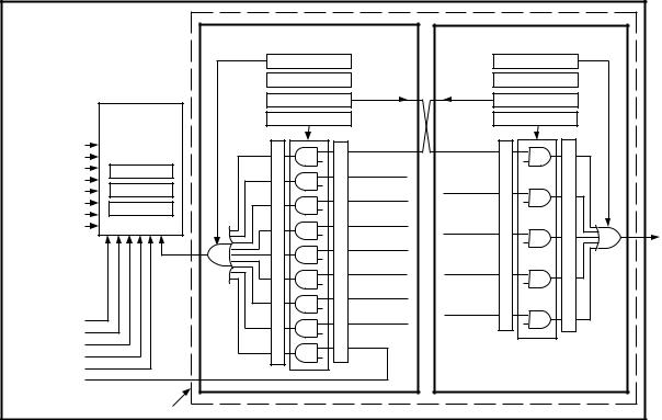
Interrupt Controller
The DSP core of the ADSP-2141L provides a powerful set of interrupt sources. A total of 14 interrupt sources are available, although two pairs are multiplexed, yielding 12 simultaneous sources. Refer to Table I.
The ADSP-2141L enhances the existing interrupt controller within the ADSP-218x DSP Core with some additional functions related to the crypto functional blocks and the external host bus interfaces. Two additional interrupt controller subsystems have been added to the basic interrupt controller as shown in Figure 5.
The DSP interrupt controller allows programming between one and nine sources for the IRQ2 interrupt to the DSP. The DIMASK register provides the mask to select which interrupt source is enabled. A pair of status registers, DUMSTAT and DMSTAT, allow the DSP firmware to read the status of any interrupt source either before or after the mask is applied.
The host interrupt controller allows programming between one and five sources for the PF7/INT_H interrupt output signal (which may be connected to the interrupt input of the host system). The HMASK register provides the mask to select which interrupt source is enabled. A pair of status registers, HUMSTAT and HMSTAT, allow the host firmware to read the status of any interrupt source either before or after the mask is applied.
Laser Variable Storage
The laser variables are configured through 256 Fuses in the ADSP-2141L, which are programmed during IC manufacture. Each ADSP-2141L produced is programmed with a unique set of Laser Variables.
•Local Storage Variable (LSV—the Master Key-Encryption-Key)
•Internal Seed Variable
•48-Bit Program Control Data (enables/disables various features and configures the ADSP-2141L)
•CRC of the Laser Data (to verify integrity of the laser bits)
The LSV is a unique triple DES master key-encrypting key that allows the ADSP-2141L to securely store data (primarily other keys) off-chip for later reloading. This is necessary if more storage space is needed than is available with on-chip RAM, or if keys need to be saved and restored after a power outage. Each ADSP-2141L produced is programmed with a unique, randomly generated local storage variable.
The internal seed variable is used to randomly initialize the RNG circuits before the entropy is mixed in. Each ADSP-2141L produced is programmed with a unique, randomly generated internal seed variable which is loaded into the RNG at chip boot time and cannot ever be read by software.
The 48 Program Control Data Bits (PCDBs) include configuration for permitted key lengths, algorithm enables, red KEK loading, internal IC pulse timing characteristics. The PCDBs provide configuration data that falls into three categories:
•Internal IC pulse-timing characteristics
•ADSP-2141L hardware version number field
•ADSP-2141L feature enables
The first two categories consist of data that cannot be altered once the ADSP-2141L has been fabricated.
The feature enables can be overridden using a factory token enabler which may be passed to the CGX kernel as part of the CGX_INIT command. This token is digitally signed with an IRE private key and verified internal to the ADSP-2141L with its public key. The CGX_INIT command is documented in the
ADSP-2141 CGX Interface Programmer’s Guide (available from http://www.ire-ma.com/proddoc.htm).
DSP |
|
|
|
|
|
|
|
DSP INTERRUPT CONTROLLER |
HOST INTERRUPT CONTROLLER |
||||
|
|
DICFG |
|
|
|
HICFG |
|
|
DICLR |
|
|
|
HICLR |
|
|
DIFRC |
|
|
|
HIFRC |
INTERNAL |
ADSP-2183 |
DIMASK |
|
|
|
HIMASK |
INTERRUPTS |
|
|
|
|
|
|
INTERRUPT |
|
HOST |
DSP |
|
|
|
|
|
|
|
|||
RESET |
CONTROLLER |
|
|
|
||
|
INTERRUPT |
INTERRUPT |
HOST UNMASKED STATUS REGISTER |
|
||
POWER DOWN |
|
|
H/E CONTEXT1 |
|
|
|
SPORT0 Tx |
|
|
|
|
||
ICNTL |
|
DONE |
H/E CONTEXT1 |
|
||
SPORT0 Rx |
|
|
|
|
||
IMASK |
|
H/E CONTEXT0 |
DONE |
|
||
BDMA INT |
|
|
||||
|
DONE |
|
|
|||
TIMER INT |
|
|
|
|
||
IFC |
|
HOST |
|
|
||
SPORT1 Tx |
|
H/E CONTEXT0 |
|
|||
|
|
WROTE CMD |
|
|||
SPORT1 Rx |
|
|
|
|||
|
|
DMA xFER |
DONE |
INTH |
||
|
|
|
|
|||
|
IRQ2 |
|
DONE |
DSP |
TO HOST |
|
|
DSP REGISTERMASKEDSTATUS |
DSPUNMASKEDREGISTERSTATUS |
DMA xFER |
WROTE |
HOSTREGISTERMASKEDSTATUS |
|
|
QUEUED |
CMD |
||||
|
EXT MEM |
|
||||
EXTERNAL |
CONFLICT |
HASH/ENC |
||||
INTERRUPTS |
HASH/ENC |
ERROR |
||||
IRQE |
ERROR |
|
||||
|
|
|
|
|
|
|
IRQL0 |
|
|
IRQ2 |
|
|
|
IRQL1 |
|
|
|
|
|
|
|
|
|
|
|
|
|
IRQ0 |
|
|
|
|
|
|
IRQ1 |
|
|
|
|
|
|
IRQ2 |
|
|
|
|
|
|
CRYPTO INTERRUPT |
|
|
|
|
|
|
SUBSYSTEM BOUNDRY |
|
|
|
|
|
|
Figure 5. Interrupt Controller Block Diagram
–8– |
REV. 0 |

ADSP-2141L
PIN FUNCTIONS
I/O Descriptions
This section describes the physical I/O hardware on the ADSP-2141L.
PIN FUNCTION DESCRIPTIONS–I/O Hardware
|
# of |
Input/ |
|
|
Pin Name |
Pins |
Output |
Function |
|
|
|
|
|
|
External Memory Bus |
|
|
|
|
Address [25:0] |
26 |
O |
Address Output Pins for Program, Data, Byte and I/O Spaces (13 Bits 2183, 13 Bits |
|
|
|
|
from Overlay Register) Note: A0 not used for 32-bit memory. |
|
Data [31:0] |
32 |
I/O |
Data I/O Pins for Program and Data Memory Spaces |
|
|
|
|
D31:0 are used for wide-bus data memory. |
|
|
|
|
D23:0 are used for DSP Program RAM. |
|
|
|
|
D23:8 are used for I/O Space. |
|
|
|
|
D23:8 are used for DSP Data RAM. |
|
|
|
|
D15:8 are used for byte memory. |
|
|
|
|
D23:16 are also used as Byte Space Addresses |
|
|
|
|
|
|
Interrupts |
|
|
|
|
IRQ2 |
1 |
I |
Edgeor Level-Sensitive Interrupt Request |
|
IRQL0 |
1 |
I |
Level-Sensitive Interrupt Requests |
|
IRQL1 |
1 |
I |
Level-Sensitive Interrupt Requests |
|
IRQE |
1 |
I |
Edge-Sensitive Interrupt Request |
|
|
|
|
|
|
Bus Signals |
|
|
|
|
BR |
1 |
I |
Bus Request Input |
|
BG |
1 |
O |
Bus Grant Output |
|
BGH |
1 |
O |
Bus Grant Hung Output |
|
PMS |
1 |
O |
Program Memory Select Output |
|
DMSL |
1 |
O |
Data Memory Select Output (Lower 16 Bits for 32-Bit DM) |
|
DMSH |
1 |
O |
Upper Memory Select Output (Upper 16 Bits for 32-Bit DM, Not Used for 16-Bit DM) |
|
BMS |
1 |
O |
Byte Memory Select Output |
|
IOMS |
1 |
O |
I/O Space Memory Select Output |
|
CMS |
1 |
O |
Combined Memory Select Output (PMS, DMS*, IOMS, BMS) |
|
RD |
1 |
O |
Memory Read Enable Output |
|
WR |
1 |
O |
Memory Write Enable Output |
|
|
|
|
|
|
Miscellaneous |
|
|
|
|
MMAP |
1 |
I |
Memory Map Select Input (1 = Overlay External at 0x0000) |
|
BMODE |
1 |
I |
Boot Option Control Input (0 = BDMA, 1 = IDMA) |
|
CLKIN, XTAL |
2 |
I |
Clock or Quartz Crystal Input (1/2 of the ADSP-2141 Clock) |
|
CLKOUT |
1 |
O |
Processor Clock Output |
|
|
|
|
|
|
Serial Ports |
|
|
|
|
SPORT0 |
|
|
|
|
SCLK0 |
1 |
I/O |
Serial Port 0 Clock |
|
DR0 |
1 |
I |
Serial Port 0 Receive Data Input |
|
RFS0 |
1 |
I/O |
Serial Port 0 Receive Frame Sync |
|
DT0 |
1 |
O |
Serial Port 0 Transmit Data Output |
|
TFS0 |
1 |
I/O |
Serial Port 0 Transmit Frame Sync |
|
SPORT1 |
|
|
|
|
Port Configuration |
|
|
|
|
(System Control Reg) –> |
|
|
1 = Serial Port |
0 = Other |
SCLK1 |
1 |
I/O |
Serial Port 1 |
Clock |
DR1 |
1 |
I |
Serial Port 1 Receive Data Input |
Flag In |
RFS1 |
1 |
I/O |
Serial Port 1 Receive Frame Sync |
IRQ0 |
DT1 |
1 |
O |
Serial Port 1 Transmit Data Output |
Flag Out |
TFS1 |
1 |
I/O |
Serial Port 1 Transmit Frame Sync |
IRQ1 |
|
|
|
|
|
Power-Down |
|
|
|
|
PWD |
1 |
I |
Power-Down Initiate Control |
|
PWDACK |
1 |
O |
Power-Down Acknowledge |
|
|
|
|
|
|
REV. 0 |
–9– |
ADSP-2141L
|
# of |
Input/ |
|
Pin Name |
Pins |
Output |
Function |
|
|
|
|
Flags |
|
|
|
PF6:0 |
7 |
I/O |
Programmable I/O Pins |
PF7/INT_H |
1 |
I/O |
Programmable I/O Pin–or–Interrupt Output (Host Mode) |
|
|
|
|
Emulator |
|
|
|
EE |
1 |
|
(Emulator Only) |
EBR |
1 |
|
(Emulator Only) |
EBG |
1 |
|
(Emulator Only) |
ERESET |
1 |
|
(Emulator Only) |
EMS |
1 |
|
(Emulator Only) |
EINT |
1 |
|
(Emulator Only) |
ECLK |
1 |
|
(Emulator Only) |
ELIN |
1 |
|
(Emulator Only) |
ELOUT |
1 |
|
(Emulator Only) |
|
|
|
|
Serial EEPROM Interface |
|
|
|
EE_DI |
1 |
O |
Serial EEPROM Data In |
EE_DO |
1 |
I |
Serial EEPROM Data Out |
EE_CS |
1 |
O |
Serial EEPROM Chip Select |
EE_SK |
1 |
O |
Serial EEPROM Clock |
|
|
|
|
Bus Select |
|
|
|
BUS_MODE |
1 |
I |
Processor Bus Select |
BUS_SEL |
1 |
I |
Bus Select |
|
|
|
|
PCI Bus (Dedicated Pins) |
|
|
|
PCI_CLK |
1 |
I |
PCI Clock |
PCI_PAR |
1 |
I/O |
PCI Parity Bit |
PCI_IRDY |
1 |
I/O |
PCI Initiator Ready |
PCI_STOP |
1 |
I/O |
PCI Abort Transfer |
|
|
|
|
*When DMS is enabled for generation of CMS, the CMS is activated for DSP access to external memory only, NOT for DMA controller accesses.
Bus Mode Descriptions
The Pin Function Descriptions, Bus Mode table, shows the multiplexed pins in 2183 and PCI mode. For more information on the PCI pins MPLX1–MPLX12, see the Pin Functions Description–PCI Mode Multiplex Bus table on the following page.
PIN FUNCTION DESCRIPTIONS—Bus Mode
|
# of |
Input/ |
2183 Mode |
PCI Mode |
Bus Mode |
Pins |
Output |
(bus_mode = 0, bus_sel = 0) |
(bus_mode = 1, bus_sel = 0) |
|
|
|
|
|
MPLX_RESET |
1 |
I |
RESET_1 |
Pci_rst |
MPLX1 |
1 |
I/O |
|
Pci_cbe3 |
MPLX2 |
1 |
I/O |
|
Pci_cbe2 |
MPLX3 |
1 |
I/O |
|
Pci_cbe1 |
MPLX4 |
1 |
I/O |
|
Pci_cbe0 |
MPLX5 |
1 |
I |
IRD |
Pci_idsel |
MPLX6 |
1 |
I |
IWR |
Pci_gnt |
MPLX7 |
1 |
I/O |
IS |
Pci_frame |
MPLX8 |
1 |
I/O |
IAL |
Pci_devsel |
MPLX9 |
1 |
I/O |
IACK |
Pci_trdy |
MPLX10 |
1 |
I/O |
FL0 |
Pci_perr |
MPLX11 |
1 |
I/O |
FL1 |
Pci_serr |
MPLX12 |
1 |
O |
FL2 |
Pci_req |
MPLX_BUS[31:0] |
32 |
I/O |
IAD15:0 |
Pci_ad15:0 |
|
|
|
N/C 31:16 |
Pci_ad31:16 |
|
|
|
|
|
Power |
|
|
|
|
GND |
24 |
– |
Ground Pins |
|
VDD |
22 |
– |
Power Supply Pins (3.3 V) |
|
Total: |
208 |
Includes the pins from this table and the I/O Hardware Pin Function Description table. |
||
|
|
|
|
|
–10– |
REV. 0 |