

4 - Position Reference Systems and Equipment
4.1 - General
Accurate, reliable and continuous position information is essential for dynamic positioning. Some DP operations require better than 3m relative accuracy. A DP control system requires data at a rate of once per second to achieve high accuracy. Reliability is, of course, of vital importance, to operations where life and property may be put at extreme risk through incorrect position data10.
All DP vessels have position reference systems (PRS), (sometimes referred to as position monitoring equipment or PME), independent of the vessel's normal navigation suite. Five types of PRS are in common use in DP vessels; Hydroacoustic Position Reference (HPR), Taut Wire, DGPS, Laser-based systems (Fanbeam and CyScan) and Artemis. A brief description will be given of each.
DP control systems ‘pool’, or combine, position reference data from two or more position reference systems. If only one position reference system is enabled into the DP then it is simply checked, filtered and used. If two or more are available, then the system needs to use both equally or according to their individual performance.
In all modern DP systems the weighted average option can be selected, whereby individual position references are weighted in inverse proportion to the variance or ‘spread’ of position data; the higher the weighting for an individual position reference system, the greater the influence of that system in the position calculation.
Early DP control systems did not have the capability to learn from the past performance other than by the integral terms of the controller. Modern systems are able to improve station keeping performance by using a Karman filter, which provides a model of recent performance to improve present performance.
For any operations requiring DP redundancy (equipment Class 2 or 3 operations) it is necessary to utilise three position references. Two PRSs are not adequate, because if one has failed, contradictory reference data provides an impass, whereas three systems provide two-out-of-three voting to identify a rogue sensor.
Where three PRSs are required, the DPO should choose systems that are different. This reduces the probability of common-mode failure, where one event may result in a loss of position.
A brief description will be given of the five commonly used position reference systems.
4.2 - Hydroacoustic Position Reference (HPR)
Underwater acoustics have many applications, one of which is the provision of position reference for DP purposes13.
Acoustic positioning is also used for tracking of underwater vehicles or equipment, the marking of underwater features or hardware and the control of subsea equipment by means of acoustic telemetry.
There are three types of acoustic position reference systems in common use - ultraor supershort baseline systems (USBL or SSBL), short baseline systems (SBL) and long baseline
systems (LBL). Each has advantages and disadvantages which determine when and how each is used.
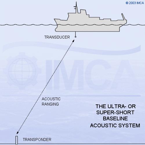
4.2.1 - Ultraor Super-Short Baseline Acoustic System
The principle of position measurement involves communication at hydroacoustic frequencies between a hull-mounted transducer and one or more seabed-located transponders. The ultraor super-short baseline (SSBL) principle means that the measurement of the solid angle at the transducer is over a very short baseline (the transducer head).
Sketch 4.1 SSBL principles
An interrogating pulse is transmitted from the transducer. This pulse is received by the transponder on the seabed, which is triggered to reply. The transmitted reply is received at the transducer. The transmit/receive time delay is proportional to the slant and range. So range and direction are determined. The angles and range define the position of the ship relative to that of the transponder. The measured angles must be compensated for values of roll and pitch.
The vessel must deploy at least one battery-powered transponder. They can be deployed by downline from the vessel, by an ROV or simply dropped overboard.
The performance of an acoustic system is often limited by acoustic conditions in the water. Noise from vessel thrusters and other sources, aeration and turbulence12, 13 will all be detrimental
to efficient acoustic positioning. Thus the limits of the system are ill-defined. In addition, layering can cause errors, especially when the horizontal displacement from the vessel is large.
Acoustic systems are supplied by a number of manufacturers, notably Kongsberg Simrad, Sonardyne and Nautronix. All use frequencies in the 20-30 kHz band. Some transponders are compatible with more than one supplier’s equipment.
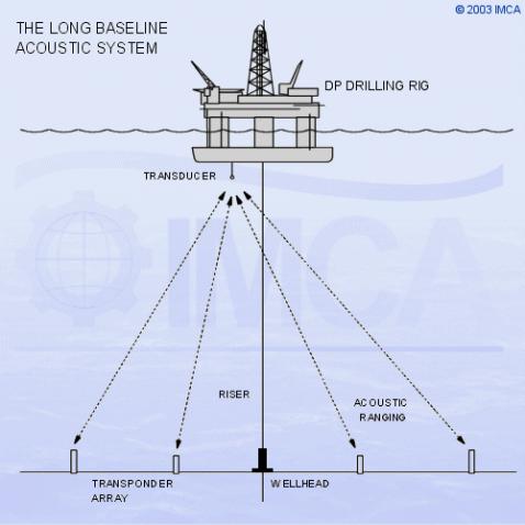
4.2.2 - Long Baseline System
In deepwater locations, where the accuracy of the other types degrades, the long baseline (LBL) becomes more appropriate. LBL systems are in extensive use in drilling operations in deep water areas (>1,000m).
Sketch 4.2 LBL system
The long baseline system uses an array of three or more transponders laid on the seabed in the vicinity of the worksite. Typically the array will form a pentagon (5 transponders) on the seabed, with the drillship at the centre above. One transducer upon the vessel interrogates the transponder array, but instead of measuring range and angular information, ranges only are measured, because the baseline distances have already been calibrated (distances between transponders). Position reference is obtained from range-range geometry from the transponder locations. Calibration is done by allowing each transponder to interrogate all the others in the array, in turn. If, at the same time, the vessel has a DGPS or other geographically-referenced system, then the transponder array may also be geographically calibrated. Accuracy is of the