

5.10 - Offtake Tanker and FPSO Operations
Tankers intended to load at Offshore Loading Terminals (OLTs) will be fitted with systems very similar to those in any other DP-capable vessel, but configured specifically for the offshore loading function.
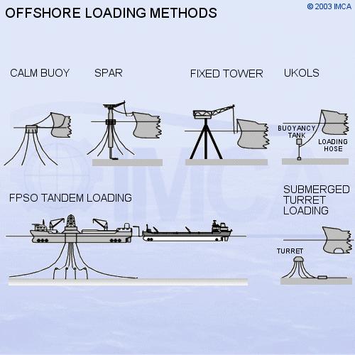
The installations which support offtake tanker operations vary from field to field. Typical installations are Spar buoys, which are large floating tower structures moored by a spread of mooring lines. Spar buoys usually carry a rotating turntable at the top to handle vessel moorings and hose handling equipment.
Sketch 5.11 - OLT configurations
A UKOLS facility has a loading hose connected to a mid-water buoy. The buoy is positively buoyant and is moored at a fixed depth, above a gravity-based housing or pipeline end manifold (PLEM). Vessels using this facility have no need for a mooring hawser; the only connection to the buoy is the hose. A more recent development is the submerged turret loading (STL) system, where the loading connections are located in a subsea buoy. The buoy is moored above the PLEM at a depth greater than the draught of the offtake vessel. The STL is mated into a docking port built into the forebody of the vessel, and carries the flowline connections to the vessel. Once locked into position, the vessel is able to weathervane using the swivel through the centre of the STL. A development of the STL is used for production.
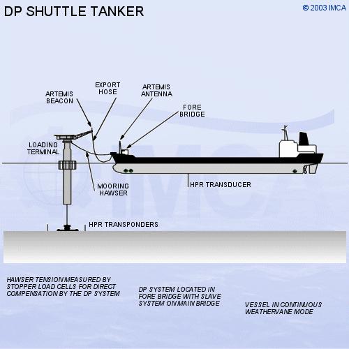
Sketch 5.12 - Shuttle tanker
5.11 - FPSO Unit Operation
Floating Production, Storage and Offtake units are becoming common in many parts of the world. Many FPSOs are able to weathervane around the turret and maintain heading into the weather.
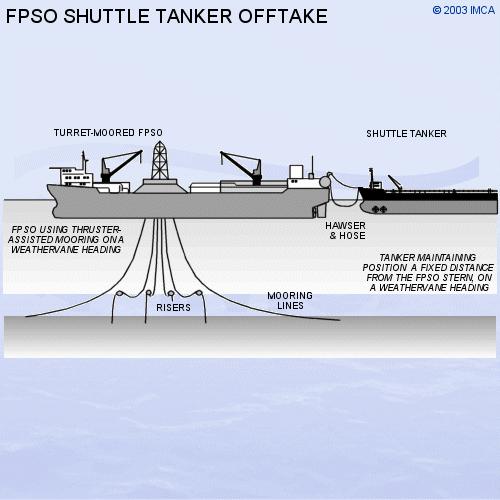
Sketch 5.13 - FPSO/shuttle tanker offtake arrangement
Most FPSOs utilise offtake tankers for export of oil, and these tankers are usually DP-capable. With any FPSO/offtake tanker operation, the tanker will experience more positioning problems than when loading from an ALP. The offtake vessel keeps position within a circle defined by the length of the loading hose. The reference position is the hose terminal point on the stern of the FPSO. The mooring and positioning system in the FPSO allows a degree of movement, especially in deep water, so the FPSO may be continually weathervaning, so that the shuttle tanker reference point will be moving. The shuttle tanker can try to follow this movement or position absolutely to pre-set limits.
In FPSO offtake operations, a relative position reference is essential. One such position reference is the relative GPS (DARPS) system, yielding position information reduced to range/bearing data from the FPSO terminal location. Another position reference is Artemis, with the fixed station located on the FPSO and the mobile station located on the tanker. The prime consideration is the clearance distance from the FPSO so that the collision risk is minimised7