

3 - Elements of a DP System
3.1 - Computers
The processors operating the DP control software are generally known as the DP computers. The main distinction of concern to the DPO is the number of computers, their methods of operation, and the level of redundancy they provide.
The computers may be installed in single, dual or triple configurations, depending upon the level of redundancy required. Modern systems communicate via an ethernet, or local area network (LAN), which may incorporate many other vessel control functions in addition to the DP.
In all DP vessels, the DP control computers are dedicated specifically for the DP function, with no other tasks. A single-computer system, or ‘simplex’ DP control system provides no redundancy. A dual or two-computer system provides redundancy and auto-changeover if the online system fails. A triple or ‘triplex’ system provides an extra element of security and an opportunity for 2-out-of-3 voting. The level of redundancy depends on the equipment class selected by the vessel (see Section 7 on system redundancy).
3.2 - Control Console
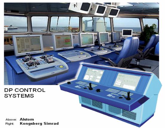
The bridge console is the facility for the DPO to send and receive data. It is the location of all control input, buttons, switches, indicators, alarms and screens. In a well-designed vessel, position reference system control panels, thruster panels and communications are located close to the DP control consoles.
3.1 Photos - Kongsberg Simrad SDP console and Alstom ‘A’ Series console
The DP control console is not always located on the forward bridge - many vessels, including most offshore support vessels have the DP console located on the after bridge, facing aft. Shuttle tankers may have the DP system situated in the bow control station although most newbuild tankers incorporate the DP system on the bridge. Possibly the least satisfactory location for the DP console is in a compartment with no outside view. This is the case in a few older drilling rigs.
The facilities for the operator vary from push-buttons and/or touch-screens to pull-down menus activated by roller balls and ‘enable’ buttons.
3.3 - Position Reference Systems
The number of position references enabled depends on a number of factors. In particular, the level of risk involved in the operation, the redundancy level that is sensible for the operation, the availability of references of a suitable type, and the consequences of loss of one or more position references.
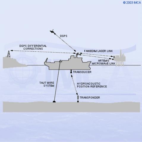
A variety of position reference systems is used by DP systems. The most common are: differential global positioning (DGPS - see Section 4.5), taut wires, hydroacoustics (HPR), and line-of-sight laser or microwave systems.
The reliability of position references is a major consideration. Each has advantages and disadvantages, so that a combination is essential for high reliability10. Individual position reference systems are described in Section 4.
Sketch 3.2 Position reference systems
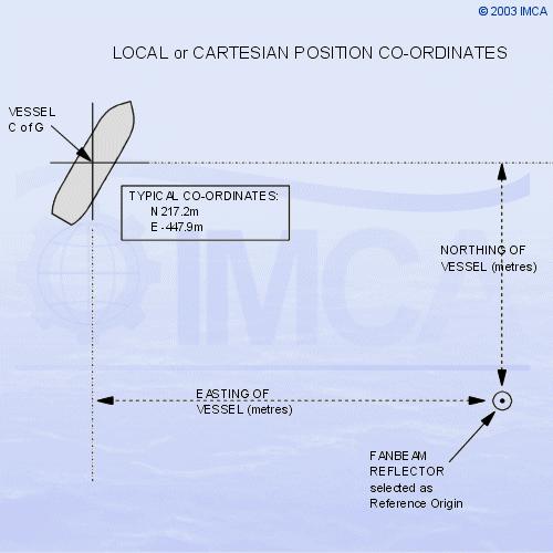
Position information from position-reference systems may be received by the DP system in many forms. In addition, the type of co-ordinate system used may be cartesian or geodetic. The DP control system is able to handle information based on either co-ordinate system. A Cartesian, or local, co-ordinate system is based upon a flat-surface two-dimensional measurement of the North/South (X) and East/West (Y) distances from a locally defined reference origin. This reference origin will be taken from one of the position reference systems (e.g. HPR transponder, fanbeam reflector, taut wire depressor weight location). This type of co-ordinate reference system is purely local, or relative, not absolute or earth-fixed.
Sketch 3.3 Local reference co-ordinates
For the DP system to handle earth-referenced type of data it is necessary to configure the DP system to accept geodetic data, or global references, such as GPS.
A DGPS system, provides co-ordinates in terms of latitude and longitude referenced to the WGS84 datum14. Most offshore operations are conducted using UTM (Universal Transverse Mercator) as the chart or worksite diagram projection. This reduces the positional co-ordinates into Northings and Eastings in metres. A fuller description of the UTM projection and coordinate system is given in Section 6.
Most modern DP control systems enable the DPO to select the type of presentation required, e.g. cartesian, geographic (lat/long or UTM). If the latter, the system will automatically calculate the UTM zone from received geodetic position measurements. The datum is usually selectable from a menu.
3.4 - Heading Reference
The DP vessel’s heading is provided by one or more gyro compasses, which transmit data to the DP control system. In vessels where redundancy is necessary, then two or three gyros are fitted.
If three gyros are fitted, then the DP system may use two-out-of-three voting to detect a gyro failure, and give an appropriate warning to the DPO. Three gyros are typically fitted in vessels complying with equipment Class 2 or 31.
A heading reference may also be available from multiple GPS receivers - see 3.5 below.
3.5 - Environment Reference
There are three main environmental forces which cause the vessel to move away from her setpoint position and/or heading. They are the forces created by wind, waves and current. (A description has been given in Section 2 relating to the determination of current values.) Current meters to provide feed forward to the DP control system are hardly ever used by DP control systems, because they are expensive, especially if high reliability is required, and generally the current forces change slowly, so that integral term of the controller is adequate. However, a facility exists in some systems for ‘quick current update’, or ‘fast learn’. This is a function which reduces the time constant of the integral term and allows the mathematical model build-period to be radically reduced. This is intended to allow the system to better react to rapidly changing tidal conditions or the new conditions after a large change of heading.
The DP control system provides no direct active compensation for waves. In practice, the frequency of the waves is such that it is not feasible to provide compensation for individual waves and the forces are too high. Wave drift forces build slowly and appear in the DP control system as current or sea force.
The roll, pitch and heave motions of the vessel are not compensated for by the DP control system, but it is necessary for the DP control system to be provided with accurate values of roll and pitch. This is to allow compensation to be applied to all the various position reference sensor inputs for their offset from the centre of gravity of the vessel. Instrumentation to measure these values is provided in the form of a vertical reference sensor (VRS), vertical reference unit (VRU) or a motion reference unit (MRU). The MRU measures accelerations by the use of linear accelerometers and calculates inclination angles.
A recent development is the provision of a system which utilises two or more DGPS receivers with antennae mounted some distance apart. The GPS fixes and motion-sensors provide data on vessel position, heading, roll, pitch and heave values. This is able to provide a reference for position and heading as well as motion in and about each axis.
All DP systems have wind sensors. This data is used to calculate wind-induced forces acting upon the vessel's hull and structure, allowing these forces to be compensated before they cause a position or heading change. Typically, a wind sensor consists of a simple transmitting anemometer, usually of the rotating-cup type.
The direction of the wind is important for vessels needing to wind or weathervane, or find the minimum power heading. A correct assessment of this heading is vitally important to some vessels, e.g. the shuttle tanker and floating production vessels, which are reliant upon finding the best heading to maximise uptime.