


2 OPERATOR MODE
2.1Introduction
Operator Mode (Level 1) is the normal day-to-day mode of the COMMANDER 250.
Frames displayed in level 1 are determined by the control strategy which is selected during configuration of the instrument – see Section 4.
 Note. Only the operating frames relevant to the configured strategy are displayed in Operator Mode.
The five control strategies are:
• |
Standard controller |
– |
page 9 |
• |
Heat/Cool controller |
– |
page 10 |
• Remote Set Point controller |
– |
page 12 |
|
• |
Profile controller |
– |
page 14 |
• Multiple Fixed Set Points controller |
– |
page 16 |
|
2-8

2 OPERATOR MODE…
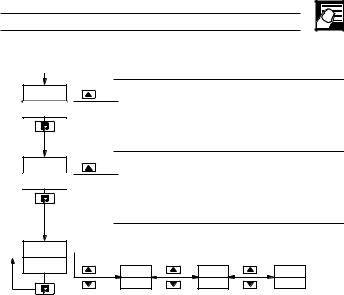
2.2Standard Controller
Auto
Man
•1
125.2 |
Process Variable Value |
|
|
||
125.8 |
Control Set Point Value (Local set point) |
|
|
[Set point low limit to set point high limit] |
|
125.2 |
Process Variable Value |
|
|
||
70 |
Control Output Value (%) |
|
OP1 |
[0 to 100% (–10% to 110% for analog output)] |
|
Adjustable in manual mode only. |
||
|
||
SPrP |
Ramping Set Point Value (Read only) |
|
The actual set point value is displayed i.e. the |
||
120.5 |
||
instantaneous value the controller is working to. |
||
CodE |
Security Code |
|
[0 to 9999] |
0Select the appropriate security code to access:
Auto-tune enable frame (Level 1),
Set Up mode (Levels 2, 3, 4).
AtnE |
Auto-tune Enable |
||
ON – |
Auto-tune on |
||
OFF |
|||
OFF – |
Auto-tune off |
||
Refer to page 16 for the Auto-tune procedure.
|
Level 1 (Operator mode) |
|
|
LEV1 |
Refer to Section 3 for levels 2, 3 and 4. |
||
|
|
|
|
OPEr |
LEV2 |
LEV3 |
LEV4 |
|
tUnE |
SEtP |
PrFL |
•1 Not displayed if the ramping set point facility is turned off – refer to Section 3.3.
2-9

…2 OPERATOR MODE
2.3Heat/Cool Controller
Auto |
125.2 |
Process Variable Value |
|
|
|||
|
125.8 |
Control Set Point Value (Local set point) |
|
|
|
[Set point low limit to set point high limit] |
|
|
125.2 |
Process Variable Value |
|
|
|
||
|
70 |
Control Output Value (Heat %) |
|
Man |
OP1 (Heat) |
[0% to 100% (0% to 110% for analog output)] |
|
125.2 |
If adjusted below 0% the 'Cool' frame is displayed. |
||
|
|||
|
|
||
|
-30 |
Control Output 2 Value (Cool %) |
|
|
OP2 (Cool) |
[0% to –100% (0% to –110% for analog output)] |
|
|
|
If adjusted above 0% the 'Heat' frame is displayed. |
|
•1 |
SPrP |
Ramping Set Point Value (Read only) |
|
|
120.5 |
The actual set point value is displayed i.e. the |
|
|
instantaneous value the controller is working to. |
CodE
0Continued on next page.
•1 Not displayed if the ramping set point facility is turned off – refer to Section 3.3.
2-10
2 OPERATOR MODE…
…2.3 Heat/Cool Controller
CodE
0 


AtnE
OFF


LEV1
OPEr
Security Code
[0 to 9999]
Select the appropriate security code to access: Auto-tune enable frame (Level 1),
Set Up mode (Levels 2, 3, 4).
Auto-tune Enable
ON – Auto-tune on
OFF – Auto-tune off
Refer to page 16 for the Auto-tune procedure.
Level 1 (Operator mode)
See Section 3 for levels 2, 3 and 4.
LEV2 |
LEV3 |
LEV4 |
tUnE |
SEtP |
PrFL |
2-11