

Alfa Laval
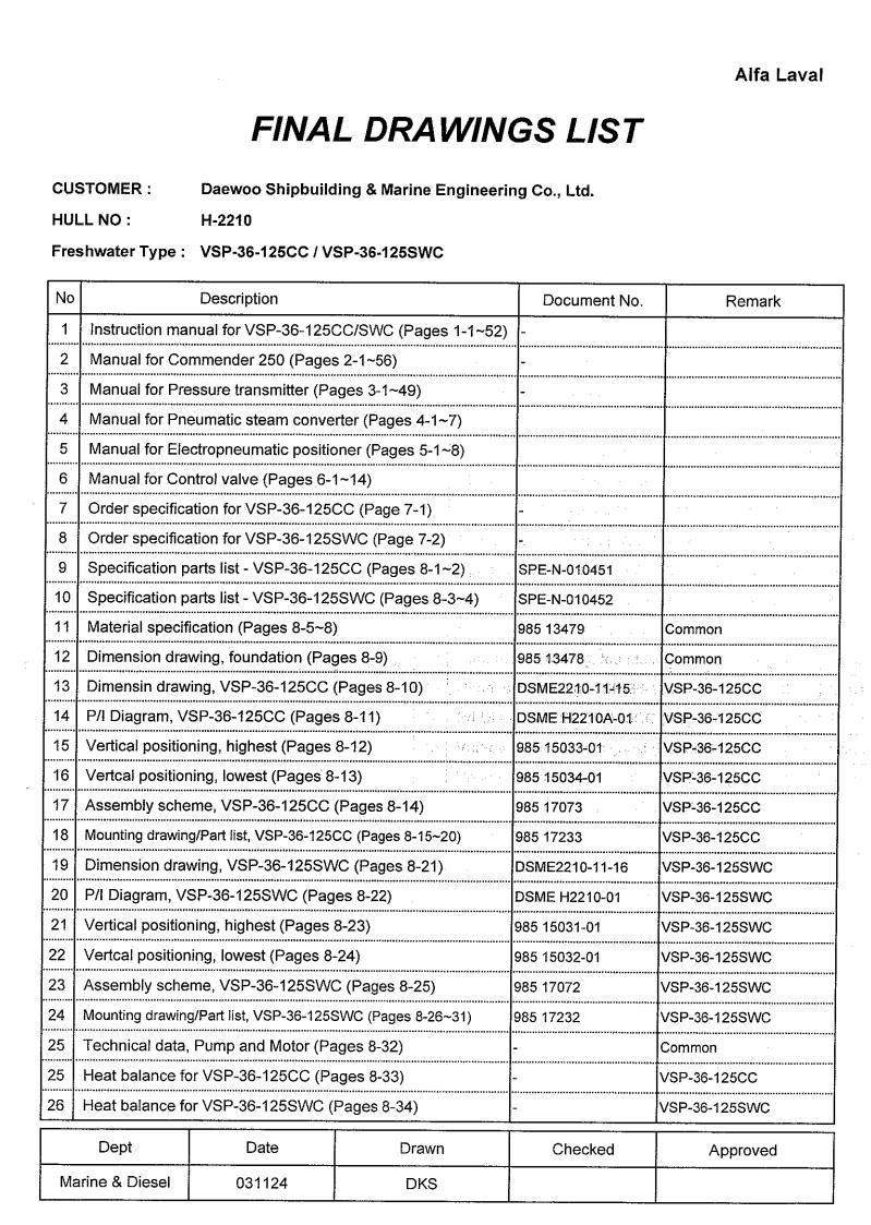
FINAL DRAWINGS LIST
CUSTOMER : |
Daewoo Shipbuilding & Marine Engineering Co., Ltd. |
|
|
|
||||
HULL NO : |
H-2210 |
|
|
|
|
|
||
Freshwater Type : VSP-36-125CC / VSP-36-125SWC |
|
|
|
|
||||
|
|
|
|
|
|
|
|
|
No |
|
Description |
|
Document No. |
Page |
|
Remark |
|
|
|
|
|
|
|
|||
1 |
Instruction manual for VSP-36-125CC/SWC |
- |
1-1~52 |
|
|
|||
2 |
Manual for Commender 250 |
|
- |
2-1~56 |
|
|
||
3 |
Manual for Pressure transmitter |
|
- |
3-1~49 |
|
|
||
4 |
Manual for Pneumatic steam converter |
|
|
4-1~7 |
|
|
||
5 |
Manual for Electropneumatic positioner |
|
|
5-1~8 |
|
|
||
6 |
Manual for desuperheating control valve |
|
|
6-1~14 |
|
|
||
7 |
Order specification for VSP-36-125CC |
|
- |
7-1 |
|
|
||
8 |
Order specification for VSP-36-125SWC |
|
- |
7-2 |
|
|
||
9 |
Specification parts list - VSP-36-125CC |
|
SPE-N-010451 |
8-1~2 |
|
|
||
10 |
Specification parts list - VSP-36-125SWC |
|
SPE-N-010452 |
8-3~4 |
|
|
||
11 |
Material specification |
|
985 13479 |
8-5~8 |
|
Common |
||
12 |
Dimension drawing, foundation |
|
985 13478 |
8-9 |
|
Common |
||
13 |
Dimensin drawing, VSP-36-125CC |
|
DSME2210-11-15 |
8-10 |
|
VSP-36-125CC |
||
14 |
P/I Diagram, VSP-36-125CC |
|
DSME H2210A-01 |
8-11 |
|
VSP-36-125CC |
||
15 |
Vertical positioning, highest |
|
985 15033-01 |
8-12 |
|
VSP-36-125CC |
||
16 |
Vertcal positioning, lowest |
|
985 15034-01 |
8-13 |
|
VSP-36-125CC |
||
17 |
Assembly scheme, VSP-36-125CC |
|
985 17073 |
8-14 |
|
VSP-36-125CC |
||
18 |
Mounting drawing/Part list, VSP-36-125CC |
|
985 17233 |
8-15~20 |
|
VSP-36-125CC |
||
19 |
Dimension drawing, VSP-36-125SWC |
|
DSME2210-11-16 |
8-21 |
|
VSP-36-125SWC |
||
20 |
P/I Diagram, VSP-36-125SWC |
|
DSME H2210-01 |
8-22 |
|
VSP-36-125SWC |
||
21 |
Vertical positioning, highest |
|
985 15031-01 |
8-23 |
|
VSP-36-125SWC |
||
22 |
Vertcal positioning, lowest |
|
985 15032-01 |
8-24 |
|
VSP-36-125SWC |
||
23 |
Assembly scheme, VSP-36-125SWC |
|
985 17072 |
8-25 |
|
VSP-36-125SWC |
||
24 |
Mounting drawing/Part list, VSP-36-125SWC |
|
985 17232 |
8-26~31 |
|
VSP-36-125SWC |
||
25 |
Technical data, Pump and Motor |
|
- |
8-32 |
|
Common |
||
25 |
Heat balance for VSP-36-125CC |
|
- |
8-33 |
|
VSP-36-125CC |
||
26 |
Heat balance for VSP-36-125SWC |
|
- |
8-34 |
|
VSP-36-125SWC |
||
|
|
|
|
|
|
|
|
|
|
|
|
|
|
|
|
|
|
|
Dept |
Date |
|
Drawn |
Checked |
|
Approved |
|
|
|
|
|
|
|
|
|
|
Marine & Diesel |
031124 |
|
DKS |
|
|
|
YHM |
|
|
|
|
|
|
|
|
|
|

No |
Description |
Document No. |
Page |
Remark |
|
|
|
|
|
|
|
27 |
Fresh water pump & Condansate pump |
984 70069.00 / |
8-35~37 |
Common |
|
984 10230.00 |
|||||
|
|
|
|
||
28 |
Control panel build on frame |
N-009859/62-03 |
8-38 |
Common |
|
29 |
Arrangement drawing for control panel |
N-010451-00-00 |
8-39 |
Common |
|
30 |
Electric diagram for control panel |
N-010451-01-00 |
8-40~51 |
Common |
|
31 |
Feed water treatment build on frame |
N-009837/38-02 |
8-52 |
Common |
|
32 |
Dimension drawing / Part list, Feed water treatment |
985 16184 |
8-53~54 |
Common |
|
33 |
Steam pressure transmitter (PT-SS-01) |
- |
8-55~56 |
Common |
|
34 |
Pressure gauge valve |
985 20103 |
8-57 |
Common |
|
35 |
Vaccuum switch (PT-E1-01) |
- |
8-58~59 |
Common |
|
36 |
Solenoid valve (VA-FR-02) |
- |
8-60~61 |
Common |
|
37 |
Strainer (ST-CO-01) |
- |
8-62~63 |
Common |
|
38 |
Steam conditioning unit automatic control valve |
N-010451/54-10 |
8-64~67 |
Common |
|
39 |
Assembly drawing, Air arrangement |
985 16458 |
8-68~69 |
Common |
|
40 |
Flow regulating valve |
- |
8-70~71 |
Common |
|
41 |
Combined brine/air ejector |
984 12230.00 |
8-72~73 |
Common |
|
42 |
T-pice for electrode unit |
984 57672 |
8-74~75 |
Common |
|
43 |
Spring loaded valve on feed water line |
984 35535.00 |
8-76~77 |
Common |
|
44 |
Spring loaded valve on fresh water line |
984 35516.00 |
8-78~79 |
Common |
|
45 |
Solenoid valve |
984 23482.00 |
8-80~81 |
Common |
|
46 |
Steel box for spare part kits |
9.2.9.2-3 |
8-82 |
Common |
|
47 |
Spare parts kit for VSP-36-125CC |
SPARES-N-010451 |
9-1 |
VSP-36-125CC |
|
48 |
Spare parts kit for VSP-36-125SWC |
SPARES-N-010452 |
9-2 |
VSP-36-125SWC |
|
49 |
Spare parts for F.W Generator |
985 16721K |
9-3~6 |
Common |
Dept |
Date |
Drawn |
Checked |
Approved |
|
|
|
|
|
Marine & Diesel |
031124 |
DKS |
|
YHM |
|
|
|
|
|
,QVWUXFWLRQ 0DQXDO IRU )UHVKZDWHU *HQHUDWRU
7\SH 963 && 6:&
%RRN 1XPEHU 2 963 IP
Alfa Laval reserve the right to make changes at any time without prior notice.
Any comments regarding possible errors and omissions or suggestions for improvement of this publication would be gratefully appreciated.
Copies of this publication can be ordered from your local Alfa Laval company.
3XEOLVKHG E\ Alfa Laval Desalt A/S
Maskinvej 5
DK-2860 Søborg
(Copenhagen) Denmark
©&RS\ULJKW $OID /DYDO 'HVDOW
This document and it content must not be copied, reproduced, transmitted or disclosed to any third party without consent of Alfa Laval Desalt.
1-2 |
O-VSP-36.fm |

7DEOH RI &RQWHQWV
6DIHW\ ,QVWUXFWLRQV DQG :DUQLQJV
1.0.0 Safety Instructions and Warnings . . . . . . . . . . . . . . . . . . . . . . . . . . . . . . . . . page 5
6\VWHP 'HVFULSWLRQ
1.0.0 Main Components. . . . . . . . . . . . . . . . . . . . . . . . . . . . . . . . . . . . . . . . . . . . . page 7 1.1.0 Working Principle . . . . . . . . . . . . . . . . . . . . . . . . . . . . . . . . . . . . . . . . . . . . . page 9 1.2.0 Freshwater Quality . . . . . . . . . . . . . . . . . . . . . . . . . . . . . . . . . . . . . . . . . . . . page 9 1.3.0 Automatic Equipment . . . . . . . . . . . . . . . . . . . . . . . . . . . . . . . . . . . . . . . . . . page 10 1.3.1 Steam Pressure . . . . . . . . . . . . . . . . . . . . . . . . . . . . . . . . . . . . . . . . . . . . . . page 10 1.3.2 Desuperheating . . . . . . . . . . . . . . . . . . . . . . . . . . . . . . . . . . . . . . . . . . . . . . page 11 1.3.3 Solenoid Valves . . . . . . . . . . . . . . . . . . . . . . . . . . . . . . . . . . . . . . . . . . . . . . page 11
1.3.4 Set Point for Operating System . . . . . . . . . . . . . . . . . . . . . . . . . . . . . . . . . . page 11 1.3.5 Set Point for Alarm System . . . . . . . . . . . . . . . . . . . . . . . . . . . . . . . . . . . . . page 12
2SHUDWLQJ ,QVWUXFWLRQV
1.0.0 Starting and Stopping Procedure . . . . . . . . . . . . . . . . . . . . . . . . . . . . . . . . . page 13 1.1.0 Starting . . . . . . . . . . . . . . . . . . . . . . . . . . . . . . . . . . . . . . . . . . . . . . . . . . . . . page 13
1.1.1 Evaporation . . . . . . . . . . . . . . . . . . . . . . . . . . . . . . . . . . . . . . . . . . . . . . . . . page 14
1.1.2 Condensation . . . . . . . . . . . . . . . . . . . . . . . . . . . . . . . . . . . . . . . . . . . . . . . . page 14 1.2.0 Adjustment of Sea Cooling Water. . . . . . . . . . . . . . . . . . . . . . . . . . . . . . . . . page 15
1.3.0 Stopping the Plant . . . . . . . . . . . . . . . . . . . . . . . . . . . . . . . . . . . . . . . . . . . . page 15
1.4.0 Long Term Standstill. . . . . . . . . . . . . . . . . . . . . . . . . . . . . . . . . . . . . . . . . . . page 15
0DLQWHQDQFH
1.0.0 Why you need to perform regular maintenance duties . . . . . . . . . . . . . . . . . page 17
1.1.0 Overhaul Intervals. . . . . . . . . . . . . . . . . . . . . . . . . . . . . . . . . . . . . . . . . . . . . page 17 1.2.0 Maintenance of Separator Vessel. . . . . . . . . . . . . . . . . . . . . . . . . . . . . . . . . page 18 1.3.0 Maintenance of Evaporator Section . . . . . . . . . . . . . . . . . . . . . . . . . . . . . . . page 19 1.4.0 Maintenance of Condenser Section . . . . . . . . . . . . . . . . . . . . . . . . . . . . . . . page 20 1.5.0 Renewal of Plate Heat Exchanger Gaskets . . . . . . . . . . . . . . . . . . . . . . . . . page 21 1.5.1 Removal of Old Gaskets . . . . . . . . . . . . . . . . . . . . . . . . . . . . . . . . . . . . . . . page 21 1.5.2 Cleaning . . . . . . . . . . . . . . . . . . . . . . . . . . . . . . . . . . . . . . . . . . . . . . . . . . . . page 22 1.5.3 Preparation of new Gaskets . . . . . . . . . . . . . . . . . . . . . . . . . . . . . . . . . . . . page 22 1.5.4 Fitting new Gaskets . . . . . . . . . . . . . . . . . . . . . . . . . . . . . . . . . . . . . . . . . . . page 22
3UHVVXUH 7HVW
1.0.0 Pressure Testing Separator . . . . . . . . . . . . . . . . . . . . . . . . . . . . . . . . . . . . . page 25
O-VSP-36TOC.fm |
1-3 |

7DEOH RI &RQWHQWV
&KHPLFDO 'RVLQJ RI 6FDOH &RQWURO &KHPLFDOV
1.0.0 Prevention of Scaling. . . . . . . . . . . . . . . . . . . . . . . . . . . . . . . . . . . . . . . . . . page 27
1.1.0 Feed Water Ratio. . . . . . . . . . . . . . . . . . . . . . . . . . . . . . . . . . . . . . . . . . . . . page 27
1.2.0 Chemical Dosage . . . . . . . . . . . . . . . . . . . . . . . . . . . . . . . . . . . . . . . . . . . . page 27 1.2.1 Scale Inhibitor Dosage Equipment for Feed Water . . . . . . . . . . . . . . . . . . page 28
1.2.2 Safety Precautions with the use of Chemicals . . . . . . . . . . . . . . . . . . . . . . page 29
7URXEOH 6KRRWLQJ
1.0.0 Test Sheet . . . . . . . . . . . . . . . . . . . . . . . . . . . . . . . . . . . . . . . . . . . . . . . . . . page 31
1.1.0 Trouble Shooting Table . . . . . . . . . . . . . . . . . . . . . . . . . . . . . . . . . . . . . . . . page 31
0DLQWHQDQFH RI )UHVKZDWHU 3XPS
1.0.0 Maintenance of Freshwater Pump Types PVVF 1525-1532-2040 . . . . . . . page 35
1.1.0 Overhaul of the Pump . . . . . . . . . . . . . . . . . . . . . . . . . . . . . . . . . . . . . . . . . page 35
1.1.1 Clearance . . . . . . . . . . . . . . . . . . . . . . . . . . . . . . . . . . . . . . . . . . . . . . . . . . page 36 1.1.2 Dismantling Pump Shaft . . . . . . . . . . . . . . . . . . . . . . . . . . . . . . . . . . . . . . . page 36
0DLQWHQDQFH RI (MHFWRU 3XPS
1.0.0 Maintenance of Ejector Pump . . . . . . . . . . . . . . . . . . . . . . . . . . . . . . . . . . . page 39
1.1.0 Overhaul of the Pump . . . . . . . . . . . . . . . . . . . . . . . . . . . . . . . . . . . . . . . . . page 39 1.1.1 Clearance . . . . . . . . . . . . . . . . . . . . . . . . . . . . . . . . . . . . . . . . . . . . . . . . . . page 40
1.1.2 Dismantling Pump Shaft . . . . . . . . . . . . . . . . . . . . . . . . . . . . . . . . . . . . . . . page 42
6DOLQRPHWHU
1.0.0 Salinometer Type DS-20 . . . . . . . . . . . . . . . . . . . . . . . . . . . . . . . . . . . . . . . page 43
1.1.0 Technical Specification . . . . . . . . . . . . . . . . . . . . . . . . . . . . . . . . . . . . . . . . page 43
1.2.0 Installation (for DS-20). . . . . . . . . . . . . . . . . . . . . . . . . . . . . . . . . . . . . . . . . page 43 1.3.0 Instructions for use . . . . . . . . . . . . . . . . . . . . . . . . . . . . . . . . . . . . . . . . . . . page 44
1.3.1 Testing the Instrument . . . . . . . . . . . . . . . . . . . . . . . . . . . . . . . . . . . . . . . . page 44
1.3.2 Adjustment of Alarm Level . . . . . . . . . . . . . . . . . . . . . . . . . . . . . . . . . . . . . page 44 1.3.3 Maintenance . . . . . . . . . . . . . . . . . . . . . . . . . . . . . . . . . . . . . . . . . . . . . . . . page 45
6SDUH 3DUWV
1.0.0 Ordering Spare Parts. . . . . . . . . . . . . . . . . . . . . . . . . . . . . . . . . . . . . . . . . . page 47 1.1.0 Alfa Laval Service . . . . . . . . . . . . . . . . . . . . . . . . . . . . . . . . . . . . . . . . . . . . page 47
,QGH[
1-4 |
O-VSP-36TOC.fm |
6DIHW\ ,QVWUXFWLRQV DQG :DUQLQJV
Should you need further clarification regarding this manual, do not hesitate to contact your local Alfa Laval representative - or call Alfa Laval Desalt directly.
7HOHSKRQH |
+45 (for Denmark) 39 53 60 00 |
7HOHID[ |
+45 (for Denmark) 39 53 65 66 |
6DIHW\ ,QVWUXFWLRQV DQG :DUQLQJV
The following symbols in this manual point out safety precautions. It means your attention is needed and your safety is involved.
:$51,1*
This symbol is used to indicate the presence of a hazard which can or will cause severe personal injury, if the warning is ignored.
&$87,21
Certain passages of the text will be marked with a caution mark. This mark indicates the presence of hazard which will or can cause property damage if the instructions are not observed.
127(
This type of instruction indicates a situation which, if not avoided, could result in damage to the equipment.
,W LV WKH RZQHU¶V DQG RSHUDWRU¶V UHVSRQVLELOLW\ WR VHH WKDW DQ\ SHUVRQ LQYROYHG ZLWK WKH XVH RU RSHUDWLRQ RI WKLV HTXLSPHQW IROORZ DOO VDIHW\ LQVWUXFWLRQV
5HDG DOO VDIHW\ LQVWUXFWLRQV FDUHIXOO\ DQG LQVLVW WKDW WKH\ ZLOO EH IROORZHG E\ WKRVH ZRUNLQJ ZLWK \RX DQG IRU \RX 1RW IROORZLQJ WKH LQVWUXFWLRQV PD\ FDXVH VHYHUH SHUVRQDO LQMXU\ RU GDPDJH WKH HTXLSPHQW EH\RQG UHSDLU
'R QRW DOORZ WKLV HTXLSPHQW WR EH XVHG LI LW LV IDXOW\ RU WKH RSHUDWRU GRHV QRW XQGHUVWDQG WKH SURSHU XVH
Samare04.f |
1-5 |
6DIHW\ ,QVWUXFWLRQV DQG :DUQLQJV
:$51,1*
The freshwater generator is not to be operated in polluted water or within
20 miles from the coast
Freshwater must not be produced from polluted water, as the produced water can be unsuitable for human consumption.
If manuals are translated to local language the unit comply with the EEC Machinery Directive and EN 292-1/2 standards. For EEC land installations manuals MUST be available in local language before installing and operating the unit.
The unit also comply with EN 50081-2 and EN 50082-2 “Industry” with regards to the
EMC directive from EEC.
:$51,1*
1RLVH KD]DUGV
•Use ear protection in noisy environments.
&UXVK KD]DUGV
•Use correct lifting tools.
•Do not work under hanging load.
%XUQ KD]DUG
•Wear gloves to avoid burns by hot surfaces.
&XW KD]DUGV
•Wear gloves to avoid cuts by sharp edges when handling machined parts.
•Wear helmet to avoid cuts by sharp edges during maintenance of the equipment.
127(
•Max. ambient temperature for the equipment is 50°C (122°F).
•Min. ambient temperature for the equipment is 0°C (32°F).
1-6 |
Samare04.fm |
6\VWHP 'HVFULSWLRQ
0DLQ &RPSRQHQWV
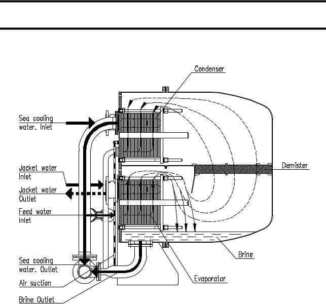
The generator consists of the following components:
1.7KH VHSDUDWRU YHVVHO
separates the produced vapour from the brine.
2.7KH HYDSRUDWRU VHFWLRQ
(heating section) Consists of a plate heat exchanger and is enclosed in lower part of the separator vessel.
3.7KH FRQGHQVHU VHFWLRQ
(cooling section) also consists of a plate heat exchanger placed in the upper part of the separator vessel.
SyVSP-36.fm |
1-7 |

6\VWHP 'HVFULSWLRQ
4.7KH FRPELQHG EULQH DLU HMHFWRU
extracts incondensable gases from the separator vessel and the evaporator vessel and the evaporator vessel, and brine from the separator vessel.
5.7KH HMHFWRU SXPS
is a combined cooling/feed/ejector water pump. The pump supplies sea water for the condenser, jet water for the combined brine/air ejector and feed water for evaporation.
6.7KH IUHVKZDWHU SXPS
extracts the produced water form the condenser and transfers it to the freshwater tank.
7.7KH VDOLQRPHWHU
continuously checks the salinity of the produced water. The alarm setpoint is adjustable.
8.7KH FRQWURO SDQHO
contains starters for the electric motors, control equipment and salinometer. The control panel is prepared for remote start/stop of all motors.
9.7KH FRQGHQVDWH SXPS
extracts condensate from the evaporator section.
10.7KH VWHDP UHJXODWLQJ HTXLSPHQW
for regulating the temperature of the hot water loop and pressure conditions of
1-8 |
SyVSP-36.fm |

6\VWHP 'HVFULSWLRQ
heating steam entering the heat exchanger. This includes a thermostatically controlled safety shut.off function (maximum inlet temperature 100°C)
11.7KH GH VXSHUKHDWLQJ XQLW
brings down the temperature of the pressure reduced steam to a steam temperature of 4-5°C above the saturation temperature in order to eliminate the risk of wet steam.
:RUNLQJ 3ULQFLSOH
The combined brine/air ejector driven by the combined cooling/ejector water pump creates a vacuum in the system in order to lower the evaporation temperature of the feedwater.
The feedwater is introduced into the evaporator section through an orifice, and is distributed itself into every second plate channel (evaporation channels).
The hot water is distributed itself into the remaining channels, thus transferring its heat to the feedwater in the evaporation channels.
Having reached boiling temperature - which is lower than at atmospheric pressure - the feed water undergoes a partial evaporation, and the mixture of generated vapour and brine enters the separator vessel, where the brine is separated from the vapour and extracted by the combined brine/air ejector.
after passing a demister the vapour enters every second plate channel in the condenser section.
' 38 6:&
The sea water supplied by the combined cooling/ejector water pump distributes itself into the remaining channels of the condenser section, thus absorbing the heat being transferred from the condensing vapour.
' 38 &&
For the condensate cooled freshwater generator the sea water in the condenser is replaced by condensate from the ship’s turbine system.
The produced freshwater is extracted by the freshwater pump and led to the freshwater tank.
)UHVKZDWHU 4XDOLW\
On the delivery side the freshwater pump an electrode unit is fitted. Together with the salinometer this unit continuously checks the salt content of the produced freshwater.
In case of too high salinity, the produced water is dumped to the bilge.
The slat content of the water is so low that it meets all common requirements to boiler feed water. If there are no special requirements form the authorities, it can be used directly as drinking water.
SyVSP-36.fm |
1-9 |

6\VWHP 'HVFULSWLRQ
:$51,1*
The freshwater distiller is not to be operated in polluted water or within 20 miles from the coast.
Freshwater must not be produced from polluted water, as the produced water can be unsuitable for human consumption.
$XWRPDWLF (TXLSPHQW
6WHDP 3UHVVXUH
The steam valve VA-SS-02 is a combined steam pressure regulating and safety cut off valve.
The steam pressure is regulated during operation by means of a controller mounted in the control panel. The controller gets the input signal from the temperature transmitter TT-SS-02 converting the actual steam temperature to an electric input signal
4-20 mA.
The output signal from the controller is given to an electric-pneumatic positioner on the combined steam pressure regulating and safety cut off valve.
The electric pneumatic positioner regulate the air to the actuator which equipped with a spring return close.
The actuator will close the valve in case:
1.Air failure in operating airsystem.
2.Too high steam temperature detected by temp. transmitter TT-SS-02. In case of malfunction of the desuperheating system, or because of too high steam inlet temperature from the steam supply system.
3.Low vacuum.
4.Low feedwater pressure.
5.Electric power supply failure.
6.Malfunction of the desuperheating system. (too high steam temperature acc. to set point of the controller causing re. valve VA-CO-02 fully opened)
1-10 |
SyVSP-36.fm |

6\VWHP 'HVFULSWLRQ
'HVXSHUKHDWLQJ
The desuperheating system secure saturated steam conditions in the steam before it enters the heat exchanger.
The amount of water injected in the steam requited during operation by the flow regulating valve VA-CO-02, getting the input from a controller mounted in the control panel.
This controller gets the signal from the temperature transmitter TT-SS-02 converting the actual team temperature to an electric input signal 4-20 mA.
The solenoid valve VA-CO-01 is controlled by the same control circuit mentioned in sect. 1.3.1 item 2, 3, 4, 5 and 6.
If the valve VA-CO-02 is fully open for more than 10 minutes, a limit switch will close for air inlet and condensate inlet.
6ROHQRLG 9DOYHV
Solenoid valves VA-FR-02 and VA-FR-05 are controlled by the salinometer in the control panel. During normal operation valve VA-FR-02 is open and VA-FR-05 is closed. In case of high salinity the valve position will change.
6HW 3RLQW IRU 2SHUDWLQJ 6\VWHP
Flow indicator FI-FT-01:
Desuperheating system regulating controller: (in control panel)
in acc. with manufacturer recommendation of feed water anti scaling chemicals.
max. 95°C.
SyVSP-36.fm |
1-11 |

6\VWHP 'HVFULSWLRQ
6HW 3RLQW IRU $ODUP 6\VWHP
Desuperheating system regulating |
110°C. |
controller: (in control panel) |
|
Timer relay 5K2: (in control panel) |
10 min. |
Pressure switch PT-ES-01: |
300 KPa g. |
Vacuum switch PT-EI-01: |
30 KPa abs. |
Salinometer: |
1,5 ppm |
Thermal relay for freshwater pump: |
1,6 A |
Thermal relay for ejector pump: |
37 A |
1-12 |
SyVSP-36.fm |
Operating Instructions
WARNING
DO NOT operate the plant in polluted water.
Freshwater must not be produced from polluted water, as the produced water will be unsuitable for human consumption.
1.0.0 Starting and Stopping Procedure
CAUTION
Before starting up please observe instructions for feedwater treatment, see “Chemical dosing of scale control chemicals”.
Please refer to P1-diagram (see “FWG Order Specification”).
1.1.0Starting
1.Open valves on the suction and discharge side of the ejector pump.
2.Open overboard valve for combined brine/air ejector.
3.Close air screw VA-El -01 on the separator.
4.Start ejector pump to create a vacuum of mm. 90%.
Pressure at combined brine/air ejector inlet minimum 300 KPa .
Back pressure at combined brine/air ejector outlet maximum 60 KPa.
For D-PU-36-125 CC only:
5.Open condensate inlet and outlet valves.
6.Start condensate supply to condenser by adjusting by-bass valve step wise, inlet the desired condensate flow is reached.
OpVSP-36.fm |
1-13 |

Operating Instructions
1.1.1 Evaporation
When there is a minimum of 90% vacuum (after maximum 10 minutes).
7.Open valve for feed water treatment VA-FT-01.
8.Secure that the air inlet for steam pressure regulating valve VA-SS-02 and desuperheating flow regulating valve VA-CO-02 is open (500-700 KPa).
9.Secure that the condensate inlet for de superheating is open (maximum 1.3
MPa).
10.Open the valve for condensate outlet to main condenser.
11.Open the main steam shut-off valve.
12.Set the operating mode for desuperheating on the temperature controller to the
MANUAL , then open the flow regulating valve VA-CO-02 (40~50 ) by using two arrow buttons on the temperature controller .
The valve opening value( ) is displayed in display window of the controller when the operating mode is manual, then the valve opening value can be adjusted manually by using two arrow buttons.
13.Make sure that the set point of steam pressure on the steam pressure controller is “0”.
Set the operating mode on the steam pressure controller to the AUTO , then open the steam pressure regulating valve VA-SS-02 gradually(5-10 KPa/min. ) by adjusting the steam pressure set point on the steam pressure controller until the specified steam pressure is reached(maximum 75 KPa A).
14.Start condensate pump immediately when the indication lamp for “Steam Valve Open” is lit up during above step 13.
●The condensate pump can not be started before the indication lamp for “Steam Valve Open” is lit up.
15.Change the operating mode for desuperheating on the temperature controller to AUTO when steam temperature is reached to 85 during above step 13.
CAUTION
The temperature setpoint for desuperheating should be higher(2~3 ) than saturated temperature at current heating steam pressure.
1-14 |
OpVSP-36.fm |

Operating Instructions
* Reference table
Pressure |
Saturated temperature |
Temperature setpoint for desuperheating |
||
|
|
|
(Recommended) |
|
0.75 KPa A |
92.0 |
|
94 |
|
0.70 KPa A |
90.0 |
|
92 |
|
0.65 KPa A |
88.0 |
|
90 |
|
0.60 KPa A |
85.9 |
|
88 |
|
1.1.2 Condensation
After approx. 3 minutes the boiling temperature will drop again, and normal vacuum is reestablished.
18.Open valve to freshwater tank.
19.Start freshwater pump.
NOTE
The freshwater pump pressure must be between 120 and 160 KPa (1.2- 1 .6 kp/cm2).
After starting the freshwater pump the flow sight glass in the air suction pipe must be empty.
CAUTION
If water remains in the flow sight glass, please refer to “Trouble shooting”.
1.2.0 Adjustment of Sea Cooling Water
The sea cooling water flow is correct, when the pressure at the inlet of the combined air/brine ejector is between 300 and 400 KPa (3.0 -4.0 kp/cm2 ).
OpVSP-36.fm |
1-15 |
Operating Instructions
1.3.0Stopping the Plant
1.Close the steam pressure regulating valve VA-SS-02 by adjusting the set point for the steam pressure controller in control panel slowly (step-wise) to 0 .
●The condensate and fresh water pumps are automatically stopped .
2.Close valve for air inlet.
3.Close the main steam shut-off valve.
4.Close valve for condensate for desuperheating inlet.
5.Close valve for feedwater treatment VA-FT-01.
6.Keep ejector pump running until the distiller unit is cooled down.
*If cooling down is performed correctly, the surface temperature at evaporator section(lower frame surface) will be below 40 .
7.Stop the ejector pump.
8.Open air screw VA-El-Ol to release a vacuum.
9.Close valves on the suction and discharge side of the ejector pump.
10.Close overboard valve for combined brine/air ejector.
11.Close the valve to freshwater tank.
CAUTION
All valves must be shut, while the distiller is out of operation. Except air screw
1.4.0 Long Term Standstill
If the distiller is out of operation for a period longer than 14 days, please observe
“Maintenance of separator vessel”.
OpVSP-36.fm |
1-16 |

0DLQWHQDQFH
:K\ \RX QHHG WR SHUIRUP UHJXODU PDLQWHQDQFH GXWLHV
Regular maintenance of the plant will improve performance and availability.
The maintenance schedule on the following pages will tell you how often service should be performed on the main components.
As the actual operating conditions of the plant are of major influence on the life time, the overhaul dates are not obligatory but only recommended intervals.
When the plant has been in operation for a longer period of time and experience has been established as to the actual performance, it will be possible to adapt the maintenance schedule.
For service on minor components please refer to component instructions.
2YHUKDXO ,QWHUYDOV
&RPSRQHQW |
2SHUDWLQJ |
$FWLRQ |
|
+RXUV |
|
|
|
|
Evaporator section |
As required |
Clean in inhibited acid bath |
|
|
|
Condenser section |
As required |
Clean with pure freshwater and |
|
|
brush |
|
|
|
Combined ejector/cooling |
8000 h |
Measure seal ring and impeller. |
water pump with motor |
|
Examine mechanical shaft seal, |
|
|
cooling water pipe passage. |
|
|
Megger-test electric motor. |
|
|
Clean pump thoroughly before |
|
|
reassembly. |
|
|
|
Freshwater extraction |
8000 h |
See above |
pump with motor |
|
|
|
|
|
Combined air/brine ejector |
8000 h |
Measure nozzles and diffuser |
|
|
and compare to measurements |
|
|
in technical specification. |
|
|
|
MV-valves |
4000 h |
Disassembly and inspect for |
|
|
damage. |
|
|
|
Demister |
8000 h |
Clean in inhibited acid bath |
|
|
|
Madpue01.fm |
1-17 |

0DLQWHQDQFH
&RPSRQHQW |
2SHUDWLQJ |
$FWLRQ |
|
+RXUV |
|
|
|
|
Manometers |
8000 h |
Adjust with control manometer |
|
|
|
Salinometer |
See separate in- |
See separate instructions |
|
structions |
|
|
|
|
0DLQWHQDQFH RI 6HSDUDWRU 9HVVHO
The separator vessels and the pressure plates for the heat exchanger sections (evaporator and condenser) are made of stainless steel with a special chemical treatment. This treatment will reestablish normal surface oxidation after workup at the factory. The preparation is a natural protection of the stainless steel.

 &$87,21
To preserve this natural protection DO NOT scrape or scratch the inside surface of the separator vessels.
Further, there are isolating layers on the separator inside walls, where the heat exchanger sections are mounted.
Whenever the sections are dismantled, these isolating layers must be checked for defects. Repair any defects according to the maintenance guide for glass flake coating.
Whenever the separator vessel is opened,
•check that the anodes are functioning
If the anodes are not functioning and/or worn, replace them.
127(
If the unit is stopped for a longer period than 14 days.
•Open separator covers and clean unit inside with freshwater.
•Let the unit dry out completely, before closing covers.
1-18 |
Madpue01.fm |
0DLQWHQDQFH
0DLQWHQDQFH RI (YDSRUDWRU 6HFWLRQ
Clean evaporator as follows:
1.Remove bolts in front cover, and open.
2.Loosen the 6 nuts in plate stack gradually, so that no nut is carrying the entire load alone
3.Remove plate stack.
127(
If some of the gaskets come loose on removing plate stack, please see section 1.5.2
4.Submerge plates completely in a hot, inhibited acid bath at maximum 50ºC. For further instructions see “Chemical dosing of scale control chemicals”.
:$51,1*
Always follow carefully the suppliers instructions when using inhibited acids.
Remember to neutralize according to suppliers instructions.
5.Examine plates and gaskets for possible damage, and remove damaged plates and/or replace damaged gaskets.
6.If a defective plate is found, remove the plate together with one of the adjacent plates.
127(
The assembly measurements must be reduced with 5.4 mm per plate, if plates are removed from plate stack.
Madpue01.fm |
1-19 |

0DLQWHQDQFH

 &$87,21
The ES and EE plate cannot be removed but must always be replaced, with a corresponding plate.
7.Reassemble evaporator section in accordance with assembly scheme.
8.Tighten plate stack to measurements stated in technical specification.
9.Pressure test evaporator section before closing front cover.
7KH HYDSRUDWRU VHFWLRQ LV SUHVVXUH WHVWHG E\ OHWWLQJ KRW ZDWHU FLUFXODWH WKURXJK WKH VHFWLRQ ZLWK E\SDVV YDOYH IRU KRW ZDWHU LQ QRUPDO UXQQLQJ SRVLWLRQ
10.When the evaporator section is found to be tight, close front cover and tighten bolts.
11.Retighten, when vacuum has been reestablished.
0DLQWHQDQFH RI &RQGHQVHU 6HFWLRQ
Clean condenser as follows:
1.Remove bolts in front cover, and open.
2.Loosen the 6 nuts in plate stack gradually, so that no nut is carrying the entire load alone.
3.Remove plate stack.
127(
If some of the gaskets come loose on removing plate stack, please see section 1.5.2
4.Scrub plates with a soft brush and plain hot water at maximum 50°C.
5.Examine plates and gaskets for possible damage, and remove damaged plates and/or replace damaged gaskets.
6.If a defective plate is found, remove the plate and one of the adjacent plates.
1-20 |
Madpue01.fm |

0DLQWHQDQFH
127(
The assembly measurements must be reduced with 5.4 mm per plate, if plates are removed from plate stack.

 &$87,21
The ES and EE plate cannot be removed, but must always be replaced, with a corresponding plate.
7.Reassemble condenser section in accordance with assembly scheme.
8.Tighten plate stack to measurements stated in technical specification.
9.Pressure test condenser section before closing front cover.
7KH FRQGHQVHU VHFWLRQ LV SUHVVXUH WHVWHG E\ OHWWLQJ VHD ZDWHU IURP WKH FRP ELQHG FRROLQJ ZDWHU HMHFWRU SXPS FLUFXODWH WKURXJK WKH VHFWLRQ
&$87,21
Before starting the combined ejector/cooling water pump, the feed water must be sealed off.
10.When the condenser section is found to be tight, close front cover and tighten bolts.
11.Retighten, when vacuum has been reestablished.
5HQHZDO RI 3ODWH +HDW ([FKDQJHU *DVNHWV
5HPRYDO RI 2OG *DVNHWV
Pull the old gaskets out of groove.
If the gasket cannot come off directly, heat the back of the gasket groove with a hot-air blower or butane gas burner.
Madpue01.f |
1-21 |
0DLQWHQDQFH
Pay attention not to overheat the plates.
You will obtain a suitable temperature, if the flame is held 10 to 15 cm behind the plate.
:$51,1*
DO NOT use DFHW\OHQH JDV
&OHDQLQJ
Charred or loose glue and rubber remains must be removed, e.g. using a rotating stainless steel brush. The width should be adapted (Ø40-50 mm, width 8-10 mm).
Thin layers of glue which are difficult to remove, may remain.
Clean the gasket groove with a clean cloth, dipped in a solvent (acetone, methyl ethyl ketone, trichlorethylene etc.).
:$51,1*
Be careful when handling these solvents, as they may be hazardous to your health. Observe suppliers’ instructions.
*DVNHWV WKDW KDYH ORRVHQHG cDQ EH JOXHG RQ &OHDQ JDVNHW JURRYH FDUHIXOO\ ZLWK D VKDUS WRRO 7KHQ FOHDQ WKH ORRVH SDUW RI WKH JDVNHW ZLWK HPHU\ FORWK RU VDQGSDSHU )LQDOO\ FOHDQ JURRYH DQG JDVNHW ZLWK D VROYHQW DQG JOXH
3UHSDUDWLRQ RI QHZ *DVNHWV
Dry new gaskets with a clean cloth that has been slightly moistened with a solvent.
)LWWLQJ QHZ *DVNHWV
1.Apply a thin layer of glue to both gasket and groove.
2.Let the glue dry for 10-15 minutes.
3.Fit new gasket into groove.
*DVNHWV PD\ VRPHWLPHV EH VOLJKWO\ VKRUW RU ORQJ
1-22 |
Madpue01.fm |

0DLQWHQDQFH
6KRUW JDVNHWV VKRXOG EH VWUHWFKHG EHIRUH EHLQJ ILWWHG LQWR WKH JURRYH
/RQJ JDVNHWV VKRXOG EH ILWWHG LQWR WKH JURRYHV DW WKH SODWH HQGV ILUVW DQG WKHQ JUDGXDOO\ EH SXVKHG LQWR WKH JURRYH WRZDUGV WKH PLGGOH
,I QHFHVVDU\ WDSH JDVNHW LQWR JURRYH
Madpue01.fm |
1-23 |

0DLQWHQDQFH
1-24 |
Madpue01.fm |
3UHVVXUH 7HVW
3UHVVXUH 7HVWLQJ 6HSDUDWRU
If there are leaks in the system, it will be necessary to carry out a pressure test in order to identify the leak:
1.Close valve on discharge side of combined cooling water/ejector pump.
2.Close discharge valve on overboard line from combined brine/air ejector.
3.Close valve on discharge line to freshwater tanks.
4.Open separator vessel in order to vent the vessel, when supplying water for pressure test.
5.Supply water (sea or freshwater) at the socket for the connection of feed water treatment.
&$87,21
Maximum pressure on the separator vessel is 150 KPa (1.5 kp/cm²) (21
PSI).
Prdpue00.fm |
1-25 |
3UHVVXUH 7HVW
1-26 |
Prdpue00.fm |
&KHPLFDO 'RVLQJ RI 6FDOH &RQWURO &KHPLFDOV
3UHYHQWLRQ RI 6FDOLQJ
During the evaporation of sea water there is always a risk of scaling on the heating surfaces. This will lead to a reduction of the K-values of the heating surface and decreasing freshwater production and reduction of plant efficiency.
In order to effectively prevent scaling the operators must be aware of the factors influencing the scale formation.
)HHG :DWHU 5DWLR
The feedwater ratio is an extremely important factor. It is defined by the relationship between the feedwater amount fed into the plant and the produced amount of freshwater.
If the feedwater ratio is reduced, the concentration will rise in the plant subsequently resulting in scale formations.
Two things may shift the feedwater ratio: first of all direct adjustment of the feedwater system, and secondly exceeding the maximum freshwater production laid out for the plant. The operators must observe the following rules at all times.
&$87,21
DO NOT adjust feedwater system. Feedwater pressure min. 300 max. 400
KPa g.
&KHPLFDO 'RVDJH
In order to control scale formations on the heating surfaces and continuously ensure long operation periods without acid cleaning the plant, it is absolutely necessary to dose scale control additives to the feedwater. The operators must follow the instructions for chemical dosing given by the chemical supplier carefully.
Cdgnpe00.fm |
1-27 |

&KHPLFDO 'RVLQJ RI 6FDOH &RQWURO &KHPLFDOV

 &$87,21
If the distiller is operated at boiling temperatures above 45°C without chemicals, frequent cleaning of the evaporator will be necessary.
We recommend that you do not operate the freshwater distiller without recommended chemical dosage at boiling temperatures above 45°C. Even at lower temperatures it can be recommended.
6FDOH ,QKLELWRU 'RVDJH (TXLSPHQW IRU )HHG :DWHU
Please refer to drawing, see “FWG Order Specification”.
•When adding chemicals mix thoroughly to ensure a homogenous blend of chemicals and water.
Use a fully soluble scale inhibitor, e.g. on polymer basis. The following products can be recommended:
NALFLEET Evaporator treatment 9-913
AMEROYAL EVAPORATOR TREATMENT
HEXAMETHAPHOSPHATE
1.Mix the required quantity for 24 hours operation in the tank according to maker’s instructions.
2.Adjust flowmeter to cover the maximum freshwater output from the distiller.
3.Flush the dosage system regularly.
1-28 |
Cdgnpe00.fm |
&KHPLFDO 'RVLQJ RI 6FDOH &RQWURO &KHPLFDOV
6DIHW\ 3UHFDXWLRQV ZLWK WKH XVH RI &KHPLFDOV
 :$51,1*
1USE eye protection and gloves. Avoid direct skin contact, eye contact or contact with clothes.
2CLEAN empty containers before disposal.
3If chemicals are spilled on clothes, rinse with water and dispose off clothes.
4If chemicals are spilled on the floor, rinse with water and suck remaining chemicals off with sand. Clean the spot immediately afterwards.
5Scale inhibitor is hazardous, if consumed in a concentrated solution.
If consumed by mistake.
,00(',$7(/< 6((. 0(',&$/ $77(17,21
6If eyes get in contact with the chemicals, rinse for at least 20 minutes.
,00(',$7(/< 6((. 0(',&$/ $77(17,21
Cdgnpe00.fm |
1-29 |

&KHPLFDO 'RVLQJ RI 6FDOH &RQWURO &KHPLFDOV
1-30 |
Cdgnpe00.fm |

7URXEOH 6KRRWLQJ
7HVW 6KHHW
Before taking any action, please fill in a test sheet to find possible causes of malfunctions.
Test sheets can be found in the back of this binder.
7URXEOH 6KRRWLQJ 7DEOH
3UREOHP |
&DXVH |
$FWLRQ |
|
|
|
Drop in production. |
Partially blocked feed water |
Dismantle evaporator section, |
|
orifice and/or sludge deposits |
and clean evaporator and ori- |
|
on hot water side. |
fice. |
|
|
|
|
Sludge on the heat exchanger |
Dismantle condenser section, |
|
plates on the sea water side. |
and clean. |
|
|
|
|
Inlet channel in evaporator/ |
Dismantle evaporator/ con- |
|
condenser plate stack |
denser section, and clean. |
|
blocked, e.g. with rust scales, |
|
|
gasket fragments etc. |
|
|
|
|
|
Too low ejector pump pres- |
See instructions for “Low Sea |
|
sure. |
Cooling water/Ejector pump |
|
|
flow / pressure”, below. |
|
|
|
|
Leakages |
Carry out a pressure test at |
|
|
max. 150 KPa (1.5 kp/cm²) |
|
|
(21.8 PSI).a |
|
|
|
|
Foreign bodies in ejector noz- |
Inspect nozzles, and clean. |
|
zles. |
Replace nozzles, if damaged. |
|
|
|
|
Too high back pressure on |
Check overboard pipe and |
|
ejector outlet side. Max 60 |
valves for blocking / function- |
|
KPa (0.6 kp/cm²) (8.7 PSI). |
ability. |
|
|
|
|
Non-return valve in air extrac- |
Replace non-return valve. |
|
tion pipe defect. |
|
|
|
|
|
Hot water temperature too |
Reduce to specified tempera- |
|
high. |
ture. |
|
|
|
|
Defective water clock. |
Examine water clock. Let the |
|
|
produced water flow through |
|
|
water clock into a 10 l pail, and |
|
|
check production with a stop |
|
|
watch. |
|
|
|
Trw26e03.fm |
1-31 |

7URXEOH 6KRRWLQJ
3UREOHP |
&DXVH |
$FWLRQ |
|
|
|
Low Sea Cooling water/Ejector |
Too low ejector pump pres- |
Clean, or replace pressure |
pump flow / pressure. |
sure. |
gauge. |
Minimum pressure 300 KPa |
|
|
(3.0 kp/cm²) (43.5 PSI). |
Suction strainer blocked. |
Clean suction strainer. |
At inlet side of ejector. |
|
|
|
Valves on suction or pressure |
Examine and overhaul defec- |
|
pipe defect. |
tive valves. |
|
|
|
|
Leakage from suction pipe to |
Repair. |
|
pump. |
|
|
|
|
|
Impeller / seal ring defective. |
Check pump maximum clear- |
|
|
ance See “Maintenance of |
|
|
Ejector Pump” |
|
|
|
|
Clocked up condenser plate |
Dismantle condenser plate |
|
stack. |
stack and clean. |
|
|
|
|
Pump rotating in wrong direc- |
Interchange phases. |
|
tion. |
|
|
|
|
Sight glass overflow. Normal |
Suction pipe leakage. |
Check suction pipe especially |
back pressure for freshwater |
|
unions and connections. Re- |
pump is 120 - 160 KPa (1.2 - |
|
pair. |
1.6 kp/cm²) (17.4 - 23.2 PSI). |
|
|
Except for JWP-16-C40 gener- |
Mechanical seal in freshwater |
Replace mechanical seal. |
ator type, where the max. back |
pump defect. |
|
pressure is 80 KPa (0.8 kp/cm²) |
|
|
(11.6 PSI). |
Impeller / seal ring in freshwa- |
Check pump maximum clear- |
|
||
|
ter extraction pipe defect. |
ance See “Maintenance of |
|
|
Freshwater Pump” |
|
|
|
|
Pump rotating in wrong direc- |
Interchange phases. |
|
tion. |
|
|
|
|
|
Valves to freshwater tank |
Check all valves. |
|
closed. |
|
|
|
|
|
Inlet filter for water clock |
Clean filter. |
|
blocked. |
|
|
|
|
Salinity too high (more than 2.0 |
Demister not fitted correctly. |
Check that demister is fitted |
ppm). |
|
against baffle and front cover. |
|
|
|
|
Front cover gasket defect or |
Replace front cover gasket. |
|
not fitted correctly. |
|
|
|
|
|
Insufficient brine extraction. |
See separate instructions for |
|
|
insufficient brine extraction, |
|
|
below. |
|
|
|
|
Electrode unit defective or |
Examine electrode unit for |
|
dirty. |
cracks. Check that it is fitted |
|
|
correctly. Clean, if necessary. |
|
|
|
1-32 |
Trw26e03.fm |
|
|
|
7URXEOH 6KRRWLQJ |
|
|
|
|
|
|
|
|
|
|
|
|
3UREOHP |
&DXVH |
$FWLRQ |
|
|
|
|
|
|
|
|
Leakage in condenser sec- |
Open distiller and pressure test |
|
|
|
tion. |
condenser. Max. 600 KPa (6.0 |
|
|
|
|
kp/cm²) (87 PSI). If there is a |
|
|
|
|
defective plate, remove togeth- |
|
|
|
|
er with adjacent plate assem- |
|
|
|
|
ble plate stack according to |
|
|
|
|
new plate number with re- |
|
|
|
|
duced assembly measure- |
|
|
|
|
ments. Check plate gaskets |
|
|
|
|
and replace, if necessary. |
|
|
|
|
|
|
|
Insufficient brine extraction - |
Ejector pump pressure too |
See special instructions for |
|
|
brine level in sight glass higher |
low. |
“Low Sea Cooling water/Ejec- |
|
|
than 20 mm. |
|
tor pump flow / pressure”, |
|
|
|
|
above. |
|
|
|
|
|
|
|
|
Foreign bodies in ejector noz- |
Check nozzles, and clean. Re- |
|
|
|
zles. |
place damaged nozzles. |
|
|
|
|
|
|
|
|
Too high back pressure down- |
Examine overboard pipe and |
|
|
|
stream of ejector. |
valves. |
|
|
|
|
|
|
|
|
Wrong dimension of feedwa- |
Examine orifice dimension - |
|
|
|
ter orifice. |
check technical specification. |
|
|
|
|
|
|
|
|
Non-return valve in brine suc- |
Examine valve and repair, or |
|
|
|
tion pipe of ejector defect. |
replace. |
|
|
|
|
|
|
|
Frequent refill of freshwater |
Leakage in evaporator sec- |
Open distiller and pressure test |
|
|
expansion tank due to loss of |
tion. |
condenser. Max. 600 KPa (6.0 |
|
|
hot water. |
|
kp/cm²) (87 PSI). |
|
|
|
|
If there is a defective plate, re- |
|
|
|
|
move together with adjacent |
|
|
|
|
plates assemble plate stack |
|
|
|
|
according to new plate number |
|
|
|
|
with reduced assembly mea- |
|
|
|
|
surements. Check plate gas- |
|
|
|
|
kets and replace, if necessary. |
|
|
|
|
|
|
|
Abnormal amperage con- |
Ejector nozzles defective. |
Replace nozzles. |
|
|
sumption of ejector pump mo- |
|
|
|
|
tor. |
Wrong dimension of feedwa- |
Check dimensions on spare |
|
|
|
ter inlet orifice. |
parts list, See List of spare part |
|
|
|
|
drawings”, and replace if nec- |
|
|
|
|
essary. |
|
|
|
|
|
|
|
|
Bearings in motor defective. |
Examine with stetoscope, and |
|
|
|
|
replace bearings, if defective. |
|
|
|
|
|
|
|
|
Contactor defective. |
Examine and replace contactor |
|
|
|
|
set, if defective. |
|
|
|
|
|
|
|
|
Breaking of phases. |
Max. 5% difference in amper- |
|
|
|
|
age between phases. |
|
|
|
|
|
|
Trw26e03.fm |
1-33 |

7URXEOH 6KRRWLQJ
1-34 |
Trw26e03.fm |

0DLQWHQDQFH RI )UHVKZDWHU 3XPS
0DLQWHQDQFH RI )UHVKZDWHU 3XPS 7\SHV 399)
The following instructions must be carefully observed whenever it becomes necessary to overhaul or repair the freshwater pump.
Please refer to drawing for item references in the text.
2YHUKDXO RI WKH 3XPS
1.Remove the QXWV on the SXPS FDVLQJ
2.Lift motor with SXPS FRYHU and LPSHOOHU clear of SXPS FDVLQJ .
3.Unscrew FRXQWHUVXQN VFUHZ (right hand thread).
4.Remove impeller. Normally, it can be removed without using dismantling tools.
5.Remove NH\
6.Remove the PHFKDQLFDO VKDIW VHDO
7.Inspect the ceramic ring, the carbon ring and the spring.
8.Replace mechanical shaft seal, if necessary. It is recommended to grease the shaft and seat for the ceramic ring with glycerine in order to make it easier to assemble the mechanical shaft seal. Please also observe separate instructions for mechanical shaft seal delivered together with the seal.
Mapvfe00.fm |
1-35 |
0DLQWHQDQFH RI )UHVKZDWHU 3XPS
9.Fit carbon ring, spring and spring holder on pump shaft.
10.Inspect impeller and the drilled sealing water channel for clogging, and clean.
5HPHPEHU WR UHSODFH JDVNHW
12. Reassemble in reverse order.
&OHDUDQFH
In connection with the inspection be sure to measure the LPSHOOHU DQG ZHDU ULQJ
in order to secure that the clearance is no more than 0.5 mm on the diameter.
&$87,21
The SXPS VKDIW must only be dismantled, if pump shaft or electric motor bearing has to be replaced.
In this case carefully observe “Dismantling pump shaft”.
'LVPDQWOLQJ 3XPS 6KDIW
1.Dismantle the pump as described above.
2.Unscrew SRLQWHG VFUHZV
3.Carefully insert two screw drivers behind the pump shaft, and loosen it.
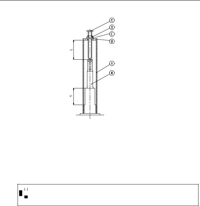
,I WKH SXPS VKDIW GRHV QRW FRPH ORRVH XVH WKH VSHFLDO GLVPDQWOLQJ WRROV VKRZQ EHORZ
7KH WRRO LV QRW $OID /DYDO 'HVDOW VXSSO\
1-36 |
Mapvfe00.fm |
0DLQWHQDQFH RI )UHVKZDWHU 3XPS
The tool consists of a pipe (A), a disc (B) with hole for the screw (C) and a nut (D), washer (E).
3OHDVH QRWH WKDW WKH OHQJWK / PXVW EH ORQJHU WKDQ WKH OHQJWK O
Place pipe around the shaft. Fasten the screw with nut and washer into the threaded hole (M12) on the shaft end.
Loosen shaft by tightening the nut while holding on to the screw.

 &$87,21
DO NOT grind the motor shaft.
4.Mount the new pump shaft on the motor shaft.
5.Make sure that the pump shaft fits the motor shaft without any obstructions, before final shaft fitting as follows:
• Tap onto the end of the pump shaft slightly with a RUBBER hammer.
6.Tighten SRLQWHG VFUHZV as follows:
Mapvfe00.fm |
1-37 |
0DLQWHQDQFH RI )UHVKZDWHU 3XPS
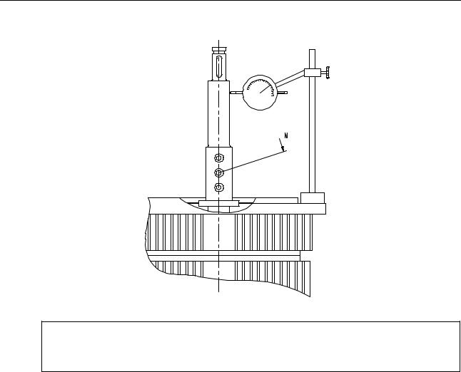
127(
The torque should be 5 Nm (0.5 kpm) and the maximum wobble 60 μ m.
7.Check the wobble of the pump shaft with a dial indicator.
8.Assemble the pump as described above.
1-38 |
Mapvfe00.fm |

0DLQWHQDQFH RI (MHFWRU 3XPS
0DLQWHQDQFH RI (MHFWRU 3XPS
,I VXSSOLHG IURP $OID /DYDO
The following instructions must be carefully observed whenever it becomes necessary to overhaul or repair the above mentioned pump. Please refer to drawing for item references in the text.
2YHUKDXO RI WKH 3XPS
1.Remove the VHW VFUHZV in SXPS FRYHU
0RWRU ZLWK PRWRU EUDFNHW SXPS FRYHU DQG LPSHOOHU FDQ QRZ EH OLIWHG FOHDU RI WKH SXPS FDVLQJ
2.Unscrew the VFUHZ (right-hand thread).
3.Remove impeller.
Macnle00.fm |
1-39 |
0DLQWHQDQFH RI (MHFWRU 3XPS
127(
Normally, the impeller can be removed without using dismantling tools.
If not, you can fit dismantling screws into the two threaded holes in the impeller.
4.Remove the key 26 and the mechanical seal 8 (including spring holder, spring and carbon ring).
5.Inspect the ceramic ring, the carbon ring and the spring. Replace, if necessary
,I PHFKDQLFDO VHDO KDV WR EH UHSODFHG SURFHHG DV IROORZV
‡8QVFUHZ VHW VFUHZ WR UHPRYH SXPS FRYHU IURP PRWRU EUDFNHW
LQ RUGHU WR JDLQ DFFHVV WR FHUDPLF ULQJ
,Q RUGHU WR PDNH LW HDVLHU WR DVVHPEOH WKH PHFKDQLFDO VHDO WKH VKDIW DQG ULQJ VHDW PD\ EH JUHDVHG ZLWK JO\FHULQH 3OHDVH DOVR UHIHU WR VHSDUDWH LQVWUXFWLRQV IRU PHFKDQLFDO VHDO GHOLYHUHG WRJHWKHU ZLWK WKH VHDO
‡$IWHU ILWWLQJ WKH FHUDPLF ULQJ ILW SXPS FRYHU WR PRWRU EUDFNHW
‡)LW FDUERQ ULQJ VSULQJ DQG VSULQJ KROGHU
6.Clean drilled cooling water channel in SXPS FRYHU
7.Inspect impeller and threaded holes for clogging.
8.5HPHPEHU WR FKDQJH WKH 2 ULQJ
9.Reassemble in reverse order.
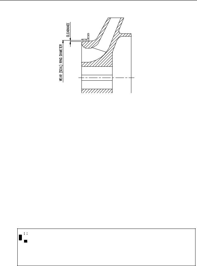
&OHDUDQFH
In connection with the inspection, the LPSHOOHU and ZHDU ULQJV are measured in order to secure that the clearance is not larger than stated in the diagram below.
1-40 |
Macnle00.fm |
0DLQWHQDQFH RI (MHFWRU 3XPS
:HDU ULQJ ‘ |
&OHDUDQFH PD[LPXP |
&OHDUDQFH PLQLPXP |
|
|
|
100 mm |
0.5 mm |
0.15 mm |
|
|
|
150 mm |
0.6 mm |
0.2 mm |
|
|
|
200 mm |
0.7 mm |
0.25 mm |
|
|
|
250 mm |
0.8 mm |
0.28 mm |
|
|
|
300 mm |
0.85 mm |
0.3 mm |
|
|
|
350 mm |
0.9 mm |
0.3 mm |
|
|
|
If the clearance is too big, replace wear rings as follows:
1.Unscrew FRXQWHUVXQN VFUHZV
2.Pull out wear (seal) rings.
3.Fit new wear rings and tighten countersunk screws.

 &$87,21
The pump shaft may only be dismantled, if pump shaft or bearings, in the electric motor have to be replaced.
Carefully observe instructions for “Dismantling pump shaft”.
Macnle00.fm |
1-41 |

0DLQWHQDQFH RI (MHFWRU 3XPS
'LVPDQWOLQJ 3XPS 6KDIW
If the VKDIW has to be dismantled due to a defect or if electric motor bearing has to be replaced, proceed as follows:
1.Unscrew SRLQWHG VFUHZV
2.Remove VKDIW . Normally this can be done without using dismantling tools.

 &$87,21
DO NOT grind the motor shaft.
3.Fit VKDIW
4.In order to make sure that the coupling is fitted correctly, tap slightly at the shaft end with a RUBBER hammer.
5.Tighten SRLQWHG VFUHZV with a torque of 35 Nm (3.5 kpm).
1-42 |
Macnle00.fm |

6DOLQRPHWHU
6DOLQRPHWHU 7\SH '6
7HFKQLFDO 6SHFLILFDWLRQ
)XQFWLRQ |
Measuring (Dot Bar) and supervising salinity of |
|
freshwater produced by seawater desalination. |
6XSSO\ YROWDJH |
90-120 V or 200-240 V AC. |
)UHTXHQF\ |
50/60 Hz |
3RZHU FRQVXPSWLRQ |
Salinometer 10 VA. |
5HOD\ FRQWDFWV |
Max. load 100 VA. |
6DOLQLW\ GLVSOD\ |
0,5 - 20 ppm (Dot Bar). |
7HPSHUDWXUH FRUUHFWLRQ |
Automatic in the range 5 - 85°C. |
$ODUP OHYHO |
Can be set to any value between 0,5 - 20 ppm. |
7HVW |
Can be checked by test switch, 10 ppm. |
2XWSXW |
4-20 mA Current Loop. |
0D[ DPELHQW WHPSHUD |
55°C. |
WXUH |
|
3URWHFWLRQ GHJUHH |
IP 54. |
,QVWDOODWLRQ IRU '6
1.Open front cover.
2.Select correct voltage select according to the main supply voltage 115 V or 230 VAC.
3.Screw salinometer on to bulkhead with six nuts.
4.Connect necessary cables to the terminals.
5.Close front cover.
6.Test salinometer function (see instructions for use).
Salise00.fm |
1-43 |
6DOLQRPHWHU
,QVWUXFWLRQV IRU XVH
1.Switch on mains.
2.Switch on sec. alarm.
Green pilot LED should light up. Dot. Bar displays the measured salinity.
7HVWLQJ WKH ,QVWUXPHQW
:$51,1*
The salinometer must be tested at least once a month, and the electrode unit must be cleaned.
Push TEST switch on.
7KH 'RW %DU VKRXOG UHDG SSP ,I WKH DODUP OHYHO LV OHVV WKDQ SSP WKH VDOLQRPHWHU ZLOO JLYH DQ DODUP
$GMXVWPHQW RI $ODUP /HYHO
1.Switch “MAINS” on.
2.Push sec. alarm off.
3.Adjust Alarm Set to desired alarm level by using the switches.
4.Switch “Sec. Alarm” on.
The salinometer is now ready for use.
If the salinity exceeds the alarm level,
•The two red alarm LEDS flash.
•Solenoid valve is activated.
•Buzzer (if fitted) and external alarm system is activated.
Cancel buzzer and external alarm system by switching “Sec. Alarm” off. Solenoid valve is not affected.
Switch “Sec. Alarm” on as soon as the salinity is normal again; i.e. when the two red
1-44 |
Salise00.fm |
6DOLQRPHWHU
LEDS are off.
0DLQWHQDQFH

 &$87,21
Remove electrode unit and inspect/clean after every 1000 hours of operation. Use a clean and dry rag. Avoid touching the electrodes with the fingers.
Salise00.fm |
1-45 |
6DOLQRPHWHU
1-46 |
Salise00.fm |

6SDUH 3DUWV
2UGHULQJ 6SDUH 3DUWV
When ordering spare parts please always state:
1.Serial number.
2.Capacity.
3.Designation.
4.Spare parts drawing number.
5.Position number.
6.Article number.
In order to identify article numbers, please refer to FWG Order Specification and other drawings.
When ordering parts for pumps proceed as follows:
1.Find article number in the list of drawings.
2.Check spare part drawing and item list with corresponding article number to identify the item to be ordered.
$OID /DYDO 6HUYLFH
The $OID /DYDO group is represented in all major ports of the world.
DO NOT hesitate to contact your $OID /DYDO representative if you have any questions, problems or require spare parts.
Spmare01.fm |
1-47 |

6SDUH 3DUWV
1-48 |
Spmare01.fm |

,QGH[ |
|
|
|
|
|
$ |
|
|
Adjustment of alarm level . . . . . . . . . . . . . . . . . . . . . . . . . . . . . . . . . . . . . . . . . . |
page 44 |
|
Alfa Laval service . . . . . . . . . . . . . . . . . . . . . . . . . . . . . . . . . . . . . . . . . . . . . . . . . |
page 47 |
|
Automatic Equipment . . . . . . . . . . . . . . . . . . . . . . . . . . . . . . . . . . . . . . . . . . . . . . |
page 10 |
|
& |
|
|
Chemical dosage . . . . . . . . . . . . . . . . . . . . . . . . . . . . . . . . . . . . . . . . . . . . . . . . . |
page 27 |
|
Cleaning . . . . . . . . . . . . . . . . . . . . . . . . . . . . . . . . . . . . . . . . . . . . . . . . . . . . . . . . |
page 22 |
|
Clearance . . . . . . . . . . . . . . . . . . . . . . . . . . . . . . . . . . . . . . . . . . . . . . . . . . . . . . |
page 40 |
|
Condensation . . . . . . . . . . . . . . . . . . . . . . . . . . . . . . . . . . . . . . . . . . . . . . . . . . . . |
page 14 |
|
' |
|
|
Desuperheating . . . . . . . . . . . . . . . . . . . . . . . . . . . . . . . . . . . . . . . . . . . . . . . . . . |
page 11 |
|
Dismantling pump shaft . . . . . . . . . . . . . . . . . . . . . . . . . . . . . . . . . . . . . . . . . . . . |
page 42 |
|
( |
|
|
Ejector Pump . . . . . . . . . . . . . . . . . . . . . . . . . . . . . . . . . . . . . . . . . . . . . . . . . . . . |
page 39 |
|
Evaporation . . . . . . . . . . . . . . . . . . . . . . . . . . . . . . . . . . . . . . . . . . . . . . . . . . . . . |
page 14 |
|
) |
|
|
Feed water ratio . . . . . . . . . . . . . . . . . . . . . . . . . . . . . . . . . . . . . . . . . . . . . . . . . . |
page 27 |
|
Fitting new gaskets . . . . . . . . . . . . . . . . . . . . . . . . . . . . . . . . . . . . . . . . . . . . . . . |
page 22 |
|
Freshwater Pump Types PVVF 1525-1532-2040 . . . . . . . . . . . . . . . . . . . . . . . . |
page 35 |
|
Freshwater Quality . . . . . . . . . . . . . . . . . . . . . . . . . . . . . . . . . . . . . . . . . . . . . . . . |
page 9 |
|
, |
|
|
Installation (for DS-20) . . . . . . . . . . . . . . . . . . . . . . . . . . . . . . . . . . . . . . . . . . . . . |
page 43 |
|
Instructions for use . . . . . . . . . . . . . . . . . . . . . . . . . . . . . . . . . . . . . . . . . . . . . . . |
page 44 |
|
/ |
|
|
Long term standstill . . . . . . . . . . . . . . . . . . . . . . . . . . . . . . . . . . . . . . . . . . . . . . . |
page 15 |
|
0 |
|
|
Main Components . . . . . . . . . . . . . . . . . . . . . . . . . . . . . . . . . . . . . . . . . . . . . . . . |
page 7 |
|
Maintenance . . . . . . . . . . . . . . . . . . . . . . . . . . . . . . . . . . . . . . . . . . . . . . . . . . . . |
page 45 |
|
Maintenance of condenser section . . . . . . . . . . . . . . . . . . . . . . . . . . . . . . . . . . . |
page 20 |
|
Maintenance of ejector pump . . . . . . . . . . . . . . . . . . . . . . . . . . . . . . . . . . . . . . . |
page 39 |
|
Maintenance of evaporator section . . . . . . . . . . . . . . . . . . . . . . . . . . . . . . . . . . . |
page 19 |
|
Maintenance of Freshwater pump . . . . . . . . . . . . . . . . . . . . . . . . . . . . . . . . . . . . |
page 35 |
|
Maintenance of freshwater pump types PVVF 1525-1532-2040 . . . . . . . . . . . . . |
page 35 |
|
Maintenance of separator vessel . . . . . . . . . . . . . . . . . . . . . . . . . . . . . . . . . . . . . |
page 18 |
|
O-VSP-36IX.fm |
1-49 |
|

,QGH[
2 |
|
Operating Hours . . . . . . . . . . . . . . . . . . . . . . . . . . . . . . . . . . . . . . . . . . . . . . . . . |
page 17 |
Ordering spare parts . . . . . . . . . . . . . . . . . . . . . . . . . . . . . . . . . . . . . . . . . . . . . . |
page 47 |
Overhaul intervals . . . . . . . . . . . . . . . . . . . . . . . . . . . . . . . . . . . . . . . . . . . . . . . . |
page 17 |
Overhaul of the pump . . . . . . . . . . . . . . . . . . . . . . . . . . . . . . . . . . . . . . . . . . . . . |
page 39 |
3 |
|
Perform regular maintenance duties . . . . . . . . . . . . . . . . . . . . . . . . . . . . . . . . . . |
page 17 |
Preparation of new gaskets . . . . . . . . . . . . . . . . . . . . . . . . . . . . . . . . . . . . . . . . |
page 22 |
Pressure testing separator . . . . . . . . . . . . . . . . . . . . . . . . . . . . . . . . . . . . . . . . . |
page 25 |
Prevention of scaling . . . . . . . . . . . . . . . . . . . . . . . . . . . . . . . . . . . . . . . . . . . . . |
page 27 |
5 |
|
Removal of old gaskets . . . . . . . . . . . . . . . . . . . . . . . . . . . . . . . . . . . . . . . . . . . |
page 21 |
Renewal of plate heat exchanger gaskets . . . . . . . . . . . . . . . . . . . . . . . . . . . . . |
page 21 |
6 |
|
Safety instructions and warnings . . . . . . . . . . . . . . . . . . . . . . . . . . . . . . . . . . . . |
page 5 |
Safety precautions with the use of chemicals . . . . . . . . . . . . . . . . . . . . . . . . . . . |
page 29 |
Salinometer type DS-20 . . . . . . . . . . . . . . . . . . . . . . . . . . . . . . . . . . . . . . . . . . . |
page 43 |
Scale inhibitor dosage equipment for feed water . . . . . . . . . . . . . . . . . . . . . . . . |
page 28 |
Set Point for Alarm System . . . . . . . . . . . . . . . . . . . . . . . . . . . . . . . . . . . . . . . . . |
page 12 |
Set Point for Operating System . . . . . . . . . . . . . . . . . . . . . . . . . . . . . . . . . . . . . |
page 11 |
Solenoid Valves . . . . . . . . . . . . . . . . . . . . . . . . . . . . . . . . . . . . . . . . . . . . . . . . . |
page 11 |
Spare Parts . . . . . . . . . . . . . . . . . . . . . . . . . . . . . . . . . . . . . . . . . . . . . . . . . . . . . |
page 47 |
Starting . . . . . . . . . . . . . . . . . . . . . . . . . . . . . . . . . . . . . . . . . . . . . . . . . . . . . . . . |
page 13 |
Starting and stopping procedure . . . . . . . . . . . . . . . . . . . . . . . . . . . . . . . . . . . . . |
page 13 |
Steam Pressure . . . . . . . . . . . . . . . . . . . . . . . . . . . . . . . . . . . . . . . . . . . . . . . . . |
page 10 |
Stopping Procedure . . . . . . . . . . . . . . . . . . . . . . . . . . . . . . . . . . . . . . . . . . . . . . |
page 13 |
Stopping the plant . . . . . . . . . . . . . . . . . . . . . . . . . . . . . . . . . . . . . . . . . . . . . . . . |
page 15 |
System description . . . . . . . . . . . . . . . . . . . . . . . . . . . . . . . . . . . . . . . . . . . . . . . |
page 7 |
7 |
|
Technical specification . . . . . . . . . . . . . . . . . . . . . . . . . . . . . . . . . . . . . . . . . . . . |
page 43 |
Telefax . . . . . . . . . . . . . . . . . . . . . . . . . . . . . . . . . . . . . . . . . . . . . . . . . . . . . . . . |
page 5 |
Telephone . . . . . . . . . . . . . . . . . . . . . . . . . . . . . . . . . . . . . . . . . . . . . . . . . . . . . . |
page 5 |
Test sheet . . . . . . . . . . . . . . . . . . . . . . . . . . . . . . . . . . . . . . . . . . . . . . . . . . . . . . |
page 31 |
Testing the instrument . . . . . . . . . . . . . . . . . . . . . . . . . . . . . . . . . . . . . . . . . . . . |
page 44 |
The combined brine-/air ejector . . . . . . . . . . . . . . . . . . . . . . . . . . . . . . . . . . . . . |
page 8 |
The condensate pump . . . . . . . . . . . . . . . . . . . . . . . . . . . . . . . . . . . . . . . . . . . . |
page 8 |
The condenser section . . . . . . . . . . . . . . . . . . . . . . . . . . . . . . . . . . . . . . . . . . . . |
page 7 |
The control panel . . . . . . . . . . . . . . . . . . . . . . . . . . . . . . . . . . . . . . . . . . . . . . . . |
page 8 |
The de superheating unit . . . . . . . . . . . . . . . . . . . . . . . . . . . . . . . . . . . . . . . . . . |
page 9 |
The ejector pump . . . . . . . . . . . . . . . . . . . . . . . . . . . . . . . . . . . . . . . . . . . . . . . . |
page 8 |
The evaporator section . . . . . . . . . . . . . . . . . . . . . . . . . . . . . . . . . . . . . . . . . . . . |
page 7 |
The freshwater pump . . . . . . . . . . . . . . . . . . . . . . . . . . . . . . . . . . . . . . . . . . . . . |
page 8 |
The salinometer . . . . . . . . . . . . . . . . . . . . . . . . . . . . . . . . . . . . . . . . . . . . . . . . . |
page 8 |
1-50 |
O-VSP-36IX.fm |
|
,QGH[ |
|
|
The separator vessel . . . . . . . . . . . . . . . . . . . . . . . . . . . . . . . . . . . . . . . . . . . . . . |
page 7 |
The steam regulating equipment . . . . . . . . . . . . . . . . . . . . . . . . . . . . . . . . . . . . . |
page 8 |
Trouble shooting table . . . . . . . . . . . . . . . . . . . . . . . . . . . . . . . . . . . . . . . . . . . . . |
page 31 |
: |
|
Warning . . . . . . . . . . . . . . . . . . . . . . . . . . . . . . . . . . . . . . . . . . . . . . . . . . . . . . . . |
page 5 |
Why you need to perform regular maintenance duties . . . . . . . . . . . . . . . . . . . . |
page 17 |
Working Principle . . . . . . . . . . . . . . . . . . . . . . . . . . . . . . . . . . . . . . . . . . . . . . . . |
page 9 |
O-VSP-36IX.fm |
1-51 |

,QGH[
1-52 |
O-VSP-36IX.fm |
COMMANDER 250 |
User Guide |
Universal Process Controller |
|
OP1
OP2
|
|
COMMANDER |
250 |
|
|
|
|
||
|
|
|
|
° C |
|
|
47 |
.5 |
|
|
|
|
° F |
|
|
|
50.0 |
||
A1 |
A2 |
R M |
|
|
|
|
|
||
Use of Instructions
Warning. |
Note. |
An instruction that draws attention to |
Clarification of an instruction or |
the risk of injury or death. |
additional information. |
Caution. |
Information. |
An instruction that draws attention to the risk of damage to the product, process or surroundings.
Further reference for more detailed information or technical details.
Although Warning hazards are related to personal injury, and Caution hazards are associated with equipment or property damage, it must be understood that operation of damaged equipment could, under certain operational conditions, result in degraded process system performance leading to personal injury or death. Therefore, comply fully with all Warning and Caution notices.
Information in this manual is intended only to assist our customers in the efficient operation of our equipment. Use of this manual for any other purpose is specifically prohibited and its contents are not to be reproduced in full or part without prior approval of Technical Communications Department, ABB Ltd.
Health and Safety
To ensure that our products are safe and without risk to health, the following points must be noted:
1.The relevant sections of these instructions must be read carefully before proceeding.
2.Warning labels on containers and packages must be observed.
3.Installation, operation, maintenance and servicing must only be carried out by suitably trained personnel and in accordance with the information given.
4.Normal safety precautions must be taken to avoid the possibility of an accident occurring when operating in conditions of high pressure and/or temperature.
5.Chemicals must be stored away from heat, protected from temperature extremes and powders kept dry. Normal safe handling procedures must be used.
6.When disposing of chemicals ensure that no two chemicals are mixed.
Safety advice concerning the use of the equipment described in this manual or any relevant hazard data sheets (where applicable) may be obtained from the Company address on the back cover, together with servicing and spares information.
GETTING STARTED
This manual is divided into 5 sections which contain all the information needed to install, configure, commission and operate the COMMANDER 250. Each section is identified clearly by a symbol as shown below.
Displays and Function Keys
•Displays and function keys
• LED Indication
•Error Messages
Operator Mode (Level 1)
•Operator menus for:
–Standard controller
–Heat/Cool controller
–Remote Set Point controller
–Profile controller
–Multiple Fixed Set Points controller
•Auto tuning
|
8 |
Set Up Mode (Levels 2, 3 and 4) |
||
|
• |
Level 2 |
– Tuning |
|
|
• |
Level 3 |
– Set Points |
|
|
|
• |
Level 4 |
– Profile |
Configuration Mode (Levels 5 and 6)
• Level 5 – Basic hardware and control functions
•Level 6 – Ranges and passwords
Installation
• Siting
•Mounting
•Electrical connections
Symbol Identification and Section Contents
2-1
CONTENTS
1 DISPLAYS AND FUNCTION KEYS |
.............................................................2- 3 |
|
1.1 |
Introduction .......................................................................................... |
2- 3 |
1.2 |
LED Alarms and Indicators ................................................................. |
2 -4 |
1.3 |
Use of Function Keys .......................................................................... |
2- 6 |
1.4 |
Error Messages ................................................................................... |
2 7 |
2 |
OPERATOR MODE ...................................................................................... |
2- 8 |
|
|
2.1 |
Introduction .......................................................................................... |
2- 8 |
|
2.2 |
Standard Controller ............................................................................. |
2- 9 |
|
2.3 |
Heat/Cool Controller .......................................................................... |
2-10 |
|
2.4 |
Remote Set Point Controller ............................................................. |
2-12 |
|
2.5 |
Profile Controller ............................................................................... |
2-14 |
|
2.6 |
Multiple Fixed Set Points Controller ................................................. |
2-16 |
|
2.7 |
Auto-tune ........................................................................................... |
2-18 |
3 |
SET UP MODE ............................................................................................ |
2- 20 |
|
|
3.1 |
Introduction ........................................................................................ |
2- 20 |
|
3.2 |
Tuning (Level 2) ................................................................................ |
2- 20 |
|
3.3 |
Set Points (Level 3) ........................................................................... |
2- 24 |
|
3.4 |
Profile (Level 4) ................................................................................. |
2- 27 |
4 CONFIGURATION MODE .......................................................................... |
2- 30 |
|
4.1 |
Introduction .................................................................................... |
2- 30 |
4.2 |
Accessing the Configuration Mode ................................................... |
2- 30 |
4.3 |
Basic Hardware and Configuration (Level 5) ................................... |
2- 32 |
4.4 |
Ranges and Passwords (Level 6) ................................................. |
2- 42 |
5 |
INSTALLATION .......................................................................................... |
2- 46 |
|
|
5.1 |
Siting .................................................................................................. |
2- 46 |
|
5.2 |
Mounting ............................................................................................ |
2 -48 |
|
5.3 |
Removing the Instrument from the Case .......................................... |
2- 50 |
|
5.4 |
Electrical Connections ...................................................................... |
2- 51 |
|
5.5 |
Relays, Arc Suppression and Outputs ............................................. |
2- 51 |
Information.
The fold-out page inside on the back cover of this manual shows all the frames in the programming levels. Space is provided on the page for writing the programmed setting or selection for each frame.
2-2