- •Operating Instructions
- •1 DISPLAYS AND FUNCTION KEYS
- •1.4 Error Messages
- •2 OPERATOR MODE
- •2.1 Introduction
- •2.2 Standard Controller
- •2.3 Heat/Cool Controller
- •2.4 Remote Set Point Controller
- •2.5 Profile Controller
- •2.6 Multiple Fixed Set Points Controller
- •2.7 Auto-tune
- •3 SET UP MODE
- •3.1 Introduction
- •3.2 Tuning (Level 2)
- •3.3 Set Points (Level 3)
- •3.4 Profile (Level 4)
- •4 CONFIGURATION MODE
- •4.1 Introduction
- •4.3 Basic Hardware and Configuration (Level 5)
- •4.4 Ranges and Passwords (Level 6)
- •5 INSTALLATION
- •5.5 Relays, Arc Suppression and Outputs
- •CUSTOMER SETUP LOG
- •CUSTOMER CONFIGURATION LOG
- •6-1 General
- •6-7 Bellows

Bellows
General
On applications involving toxic gases, radioactive materials and others where the primary seal at the valve stem is critical, a metal bellows stem seal can be used to preclude leakage as long as the integrity of the
FIG. 15
FIG. 17
Removal of Assembly from Valve
1. Remove the valve from the process line and hold valve in a bench vise clamped on the body ends.
bellows remains intact. Extreme care should be exercised in removing and/or installing the Bellows Seal Assembly to preclude damage. The metal thickness of the low pressure bellows is only 0.005” to 0.007” thick, and excess torsion will twist and deform the convolutions, damaging the assembly.
FIG. 16
FIG. 18
2. On air-to-open valves apply air pressure to diaphragm to raise innervalve off seat. (Not necessary for air-to - close valves).
7
3.Loosen stem connector locknut above travel indicator.
4.Loosen yoke nut holding topworks to bonnet.
5.Rotate entire topworks counterclockwise; top-works
stem will unscrew from stem connector.
 - Unscrew straight up or stem could be bent.
6.Finish unscrewing yoke nut and lift off topworks.
7.Loosen and unscrew bonnet assembly from body. (Fig. 16)
8.Loosen and unscrew bonnet cap and bellows assembly from bonnet. (Fig. 17)
9.Grasp bonnet stem located immediately under connector with sharp nose pliers and remove connector without allowing stem to turn.
10.Remove the bellows from the bonnet cap. At times it is necessary to cut and fish out the Teflon bellows gasket in order to free up the bellows assembly for removal.
Removing lnnervalve from Bellows Assembly and Seat from Body
1.Hold stem of bellows in a lathe collet or suitable holding device (1/8" for 1/4" valves or 3/16" for 1/2", 3/4", and 1” valves) and gently unscrew innervalve counterclockwise using a small end wrench fitting the flats on the innervalve.Avoid any side motion or bending. If the bellows stem threads unscrews before the innervalve unscrews, make a strap wrench by cutting a strip of 80 grit emery paper the width of the bellows length and roll about three revolutions clockwise around the bellows assembly with the coarse side against the bellows. Grasp the emery paper by hand and with the wrench on the innervalve flats, remove the innervalve from the bellows. Normally this procedure prevents damaging the bellows because the emery paper wrapped around the bellows gives it more support transferring the twisting forces to where the bellows is welded to the lower end plate.
2.Do not try to remove stem from bellows assembly.
3.Do not grasp the bellows in any manner other than above nor allow it to twist.
4.Unscrew seat from body with a long set socket wrench.
NOTE: If the above procedure is being done because of bellows failure, it is not necessary to be concerned about damage to the bellows.
Installing Bellows Seal Assembly, lnnervalve and Seat
Generally the foregoing steps are the reverse of disassembly, but best results will be experienced by processing in the following sequence:
1.Screw innervalve into bellows assembly only hand tight.
2.If the secondary packing in bonnet cap has not been damaged, proceed; otherwise, remove old packing but do not replace until later.
3.Place bellows-bonnet gasket carefully over bellows to flange.
4.Insert stem into bonnet cap, carefully turning in a clockwise direction until flange is seated all the way into bonnet cap.
5.Be sure gasket is home and not damaged.
6.With bellows upward, carefully screw bonnet into bonnet cap by hand until it is seated.
7.Holding bonnet in a vise, screw bonnet cap home firmly with a wrench.
8.At this point install new secondary packing if necessary, tightening gland firmly by finger tight as with a standard packed valve. (See paragraph on packing.)
9.Remove from vise and hand-install connector by hand.
10.With small wrenches on connector and flats on the innervalve, tighten firmly but prevent using any side motion.
11.With body held in a vise as instructed, screw the bonnet, bellows seal and innervalve assembly into the body.
12.When body bonnet assembly is complete, the innervalve should be off seat with the bellows in its free state and should move approximately 1/8" when pushed down before touching seat.
8
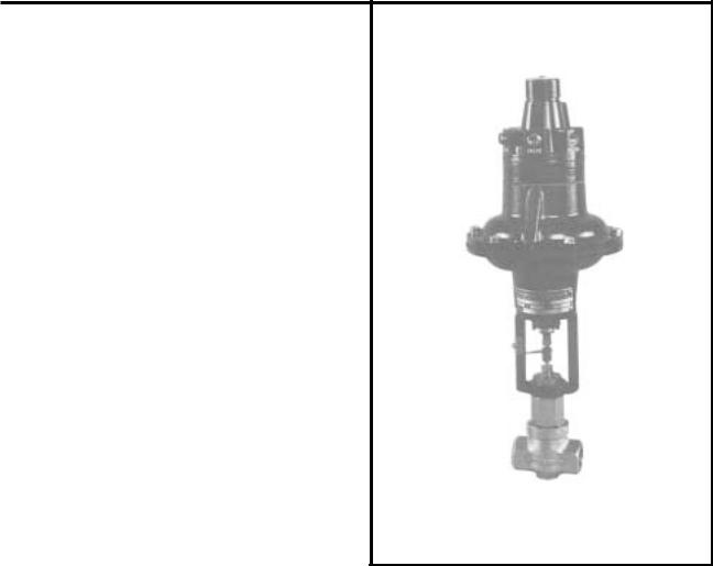
13. - With valves having “P” trims, be sure the plug enters the seat before starting the bonnet threads into the body.
14. Assemble the topworks to the body-bonnet assembly in the exact reverse order from dismantiling. On air-to open topworks remember to have air on the diaphragm, rotating the topworks until the topworks and bellows stem butts together in the middle of the connector. Use
two wrenches to tighten travel indicator lock nut to preclude twisting the bellows. If the topworks is not in the correct position with the stems butted together in the middle of the connector, rotate the topworks counterclockwise to the correct position before locking down the stem locknut. Do not rotate more than 90°
15. See stroke adjustment and pressure test.
Valve Positioners
General
Badger’s valve positioners use the full force of the air supply pressure to drive the diaphragm or piston of the pneumatic actuator to a position corresponding to the pneumatic instrument signal output from a controller (pressure, temperature, flow, etc.) and hold that position, regardless of the forces which tend to change valve position.
Like all valve positioners, Badger’s have a feedback circuit which measures position of the actuator’s diaphragm or piston. The built-in valve positioner supplies or vents air in response to the control-instrument signal stroking the valve to the required position.
Integral Mounting
Badger’s compact valve positioners incorporate a single axis force-balance principal of operation to insure accurate and stable positioning of Research Control Valves. The positioners become an integral part of the valve actuator. In all cases, including bottom loading applications, the built-in valve positioner is mounted directly on the topworks with no external piping or other exposed mechanisms.
Range Springs
The position of the diaphragm or piston in the valve actuator is sensed by the amount of compressive force exerted by the range spring on the valve actuator diaphragm assembly. Standard strokes are 7/16" and 9/16". Standard signal ranges are 3-15, 3-9, 9-15, and 6-30 PSIG. Consult the factory for other ranges.
Top Loading, Air-to-Close
Air pressure from the control instrument is exerted between the two lower diaphragms. Because of the difference in the two diaphragm areas, the resultant force is exerted in an upward direction. In balance condition, the pneumatic force on the diaphragm plus
9
the upward force exerted by the range spring is balanced by the downward force of the zero adjustment spring. In balance condition, positioner vents to atmosphere.
When control-instrument pressure increases, the diaphragm assembly will move upward closing the exhaust port and opening the pilot valve allowing supply air to pass directly to the actuator diaphragm.The supply air will drive the actuator downward. As the actuator moves down, the range spring relaxes until its force decreases enough to offset the increase in controlinstrument pressure, allowing the pilot valve to close and exhaust to open. On air-to-close valves with positioners, the supply pressure should be sufficient for function, but never excessive. For function the positioner supply pressure needs to be a minimum of 3 PSIG above instrument signal. Excessive supply pressure can result in damage to trims when the innervalve touches the seat and the signal continues down.The positioner sees this as resistance and reacts, causing the full supply pressure to be applied to the main diaphragm in the actuator.
Bottom Loading, Air-to-Open
Air pressure from control instrument is inserted between the dual upper diaphragms and the center diaphragm. Because of the difference in the two diaphragm areas, the resultant force is exerted in a downward direction. In balance condition, the pneumatic force on the diaphragm, plus the downward force exerted by the zero adjustment spring, is balanced by the upward force of the range spring. In balance condition, positioner vents to atmosphere.
When control-instrument pressure increases, the diaphragm assembly will move downward allowing the spool valve to close the exhaust port and allow the supply air to pass through interior porting to the bottom side of the diaphragm or piston in the actuator. The supply air will drive the actuator upward. As the actuator moves up, the range spring will compress until its force increases enough to offset the increase in controlinstrument pressure causing the spool valve to move, shutting off supply air to the actuator and opening exhaust.
Adjusting Zero
For ATC valves with type TLDA or Moore 73N12F positioners, zero adjustment is made with 15 psi instrument air (for 12 psi span) to the positioner, turning zero adjustment screw until valve seats at 15 psi. For
ATO valves with type BLRA or Moore 73B positioners, zero adjustment is made with 3 psi instrument air to the positioner, turning zero adjustment screw until valve seats at 3 psi. Full travel within tolerances governed by the range spring should occur on ATO or ATC valves using the standard 3-15, 3-9, 9-15, etc. instrument signal.
NOTE: Factory zero adjustments are made on Research Control Valves with positioners, using 90 PSIG air pressure piped to the upstream valve port, connecting a Tygon or rubber tubing to the downstream port and immersing the end in a water filled container to detect any leakage across the seat during zero adjustment.
Servicing
Badger’s valve positioners must be isolated from the system before service or removal can be accomplished. (Recommended procedure is to move complete valve with positioner to instrument repair bench where necessary tools and manual set air regulators are available.)
To clean pilot or spool valve, remove brass hex head sealing screw under top cap and with small sharp nose pliers, tweezers or other device, remove and clean pilot or spool valve and replace. On air-to-close TLDA and Moore 73N positioners, the pilot is a one piece unit that seldom fails due to dirty air or material such as Teflon tape getting into the pilot and causing malfunction. On air-to-open BLRA and Moore 73B positioners, the functional clearances around the spool valve is very close and more likely to fail due to dirty air or Teflon tape. Clearance is a function of bleed and must be close as possible, but large enough to function. To replace the diaphragm assembly, it is necessary to unscrew the six screws holding the positioner to the adaptor and remove the positioner assemble. Invert positioner and remove the two assembly screws in the bottom ring. When assembling the positioner diaphragm assembly to the main housing, make sure to align index grooves.
Positioners must be correctly assembled in order to function. Individual sub-assemblies such as the diaphragm assembly should be replaced as one unit.
10

TERMINOLOGY
PCV - Pressure Control Valve
LCV - Level Control Valve
TCV - Temperature Control Valve
FCV - Flow Control Valve
Topworks (Actuator) - The assembly that provides force
Positioner - Instrument added or attached to topworks for more precise control
ATO - Air to Open. Increasing air signal opens valve
ATC - Air to Close. Increasing air signal closes valve
F/O - (Fail Open) Valve opens on air failure
N/O - (Normally Open) Valve opens on air failure
F/C - (Fail Close) Valve closes on air failure
N/C - (Normally Close) Valve closes on air failure
Body Bonnet Assy - That assembly consisting of body, bonnet, gasket, innervalve, stem, seat, packing, gland and yoke nut
Trim Set - The interchangeable components in a set consisting of innervalve, stem and seat
=% - Equal Percentage. Lift versus flow characteristic
Lin. - Linear lift versus flow characteristics
Q.O. - Opening - ON-OFF service
P1 - lnlet pressure to valve
P2 - Downstream pressure from valve
HP - Delta P - Pressure drop across valve
Cv - Flow Coefficient - Water flow at 1 PSI pressure drop
Chevron Rings - Packing, molded V-rings (normally 3 per set)
Braid Tef. - Packing, rope-type braided Teflon with Teflon suspensoid lubricant
11

Notes
12

Special Information
Use this page for recording special operator information not included in the preceding (i.e., internal and supplier phone numbers, addreses, etc.)
13

Please see our website at
www.badgermeter.com
for specific contacts.
Copyright © Badger Meter, Inc. 2002. All rights reserved, all data subject to change without notice.
Due to continuous research, product improvements and enhancements, Badger Meter reserves the right to change product or system specifications without notice, except to the extent an outstanding bid obligation exists.
BadgerMeter,Inc.
6116 E. 15th Street, Tulsa, Oklahoma 74112
(918) 836-8411 / Fax: (918) 832-9962
®www.badgermeter.com


