

Linear Engine / DDL_Selection_Guide_en-EN_revA
.pdfTo size a Linear Motor, you will need to:
1.Define a Move Profile
2.Define the Load
3.Size the Motor and the Amplifier
From the move profile, we can calculate the maximum speed and the maximum acceleration/deceleration. From the load we can calculate all of the forces at constant speed and using the move profile all the dynamic forces during acceleration and deceleration. Once a motor is selected, the weight of the moving parts of the motor are added to the moving weight to calculate a total Peak Force and a total RMS force. The motor should be able to deliver the peak force and the calculated
RMS force should be higher than the continuous force to ensure a known safety margin. The coil temperature rise can also be calculated to ensure that it is lower than the intended maximum temperature rise.
The maximum bus voltage and continuous and peak current can also be calculated and compared to the selected amplifier to be sure the calculated performances can be achieved.
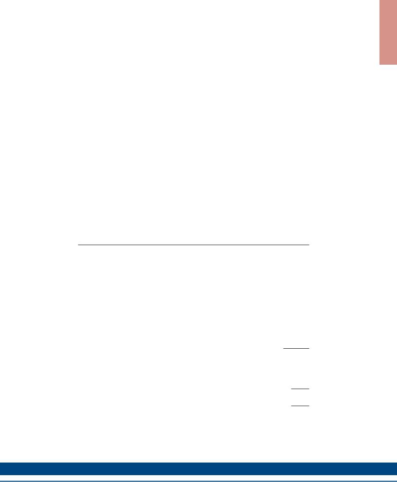
1. Move Profile
Triangular/Trapezoidal
V, Velocity |
|
|
|
|
ta |
tr |
td |
tdw |
t, time |
|
|
Units |
|
SI |
English |
Sm - Move displacement |
meters |
inches |
ta - Acceleration Time |
seconds |
seconds |
tr - Time run at constant speed |
seconds |
seconds |
td - Deceleration Time |
seconds |
seconds |
tdw - Dwell Time |
seconds |
seconds |
Vm - Max Velocity |
meter/sec. |
inches/sec |
Am - Acceleration |
meter/sec2 |
inches/sec2 |
Dm - Deceleration |
meter/sec2 |
inches/sec2 |
example: Move 0.1 meter in 100 msec assuming ta = td and tr =0, (assume triangular move)
Max Speed: Vm = 2 • Sm / ( ta + td + 2 • tr ) Vm = 2 • 0.1 / ( 100E-3)
= 2 meter/sec
Max Acceleration/Deceleration
Acceleration |
Am = Vm / ta |
|
Am = 2 / 50E-3 |
|
= 40 meter/sec2 |
|
Am “g” = Am/9.81 |
|
a (g) = 40 / 9.81 |
|
= 4.08 g |
Deceleration |
Dm = Vm/td |
|
Dm = 2/50E-3 |
|
= 40 meter/sec2 |
|
Dm “g” = Dm/9.81 |
|
d(g) = 40/9.81 |
|
= 4.08 g |
2. Load |
Units |
|
|
SI |
English |
Fext - External Force only |
N |
lbf |
(Cutting force, etc.) |
|
|
Facc - Acceleration Force only |
N |
lbf |
Fr - Run Force at constant speed |
N |
lbf |
Fdec - Deceleration Force only |
N |
lbf |
Fam - Max. Acceleration Force |
N |
lbf |
Fdm - Max. Deceleration Force |
N |
lbf |
Fdw - Dwell Force |
N |
lbf |
Frms - RMS Force |
N |
lbf |
μ - Coefficient of Friction |
– |
– |
(bearing support) |
|
|
Ml - Load Mass |
kg |
lbs |
Mc - Coil Mass |
kg |
lbs |
Mcb - Counterbalance Mass |
kg |
lbs |
Fa - Magnetic Attraction Force |
N |
lbf |
CB - Counterbalance of load in % |
– |
– |
q - Angle of Linear Displacement |
|
|
with horizontal |
|
|
(0°= horizontal, 90° vertical) |
degrees |
degrees |
g - Gravity coefficient |
9.81 m/s2 |
386 in/s2 |
n - Number of motors in parallel |
– |
– |
T U P T U O D N A G N I R I W
w w w. k o l l m o r g e n . c o m |
71 |
|
|
|
|
S T E S E L B A C X E L F H G I H
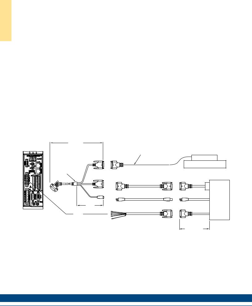
High Flex Cable Sets
Features
•High Flex cable designed for dynamic, continuous flexing applications
•Cable track compatible
•Molded, high reliability connectors
•Oil resistant PVC jacket
•105°C / 600V motor cable, 105°C / 300V Hall effect and thermal sensor cable
•CE compliant, fully shielded low impedance cable and connectors
•Fully tested, color coded, shipped with schematics
•Complete cable system for simple and reliable plug-and-play installation
Standard lengths of 1, 3, 6, 9, 12 and 15 meters available. For other lengths, consult Kollmorgen Customer Support.
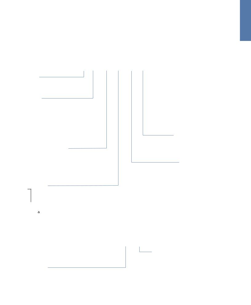
High Flex Cables for Use with AKD
|
457 +25-13 |
|
|
|
|
|
|
CONNECTOR INTERFACE |
|
|
|
|
|
|
|
|
ADAPTER |
|
|
|
|
|
|
|
ACI-AKD-A* |
|
|
(CABLE AND CONNECTOR SUPPLIED WITH ENCODER) |
|
||
|
|
|
|
|
|||
|
|
ENCODER |
|
|
|
|
|
|
|
|
|
|
|
LINEAR ENCODER |
|
STRAIN |
BLACK |
FEMALE |
MALE |
|
|
|
|
SHIELDED |
|
|
|
|
|||
RELIEF |
|
CONNECTION |
CONNECTION |
|
|
|
|
|
GRAY |
|
|
|
FEMALE |
MALE |
|
|
|
|
HALL EFFECT CABLE |
CONNECTION |
CONNECTION |
|
|
|
SHIELDED |
|
|
|
|
|
|
|
|
|
|
H1C-XX |
|
|
HALL |
|
|
|
|
GRAY, HIGH FLEX, SHIELDED |
|
GRAY |
|
|
|
|
|
|
|
||
|
|
|
MALE |
|
|
SHIELDED |
|
|
|
|
THERMAL |
|
|
|
|
|
BLACK |
|
CONNECTION |
|
|
|
|
|
SHIELDED |
|
|
T1C-XX |
|
|
THERMAL |
|
|
|
|
|
|
||
|
|
|
|
BLACK, HIGH FLEX, SHIELDED |
|
BLACK |
|
|
|
|
|
|
|
||
|
225 ±10 |
|
|
|
NOT SHIELDED |
|
|
|
|
|
|
|
|
||
|
|
|
|
MOTOR |
|
|
|
|
|
|
|
M1C-XX; M2C-XX; M3C-XX |
|
|
|
|
MOTOR |
|
|
GRAY, HIGH FLEX, SHIELDED |
|
BLUE |
MOTOR |
|
|
|
|
|
|
||
|
|
|
|
|
|
SHIELDED |
|
|
|
|
|
|
|
P1 = 400 (16) |
DDL MOTOR |
|
|
|
|
|
|
|
|
|
|
|
|
|
|
P2 = 200 (8) |
|
|
|
|
|
|
|
P3 = 100 (4) |
|
|
|
|
|
|
|
P4 = 1200 (48) |
|
|
|
|
|
|
|
STANDARD AVAILABLE LENGTHS |
|
Note: ACI-AKD-A for use with Heidenhain Encoders. ACI-AKD-B for use with Renishaw Encoders. Dimensions in mm (in)
72 |
K O L L M O R G E N |
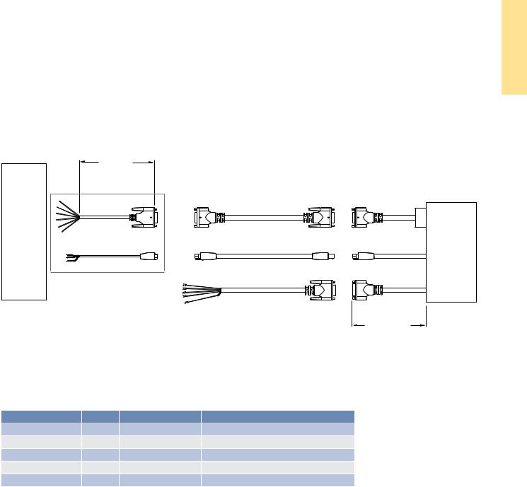
High Flex Cables for Generic Applications
457 (18) |
|
|
|
|
CONNECTOR INTERFACE |
|
|
|
|
ADAPTER |
|
|
|
|
ACI 200 |
|
|
|
|
|
|
|
FEMALE |
MALE |
|
|
HALL EFFECT CABLE |
CONNECTION |
CONNECTION |
|
|
|
|
|
|
HALL |
H1C-XX |
|
HALL |
GRAY |
|
|
||
|
GRAY, HIGH FLEX, SHIELDED |
|
GRAY |
|
SHIELDED |
|
|
|
SHIELDED |
FEMALE |
MALE |
|
|
|
CONNECTION |
CONNECTION |
THERMAL |
|
|
|
THERM |
T1C-XX |
|
THERMAL |
BLACK |
BLACK, HIGH FLEX, SHIELDED |
|
||
|
|
BLACK |
||
SHIELDED |
|
|
|
NOT SHIELDED |
|
|
MOTOR |
|
|
|
|
M1C-XX; M2C-XX; M3C-XX |
|
MOTOR |
|
|
|
|
|
|
|
GRAY, HIGH FLEX, SHIELDED |
|
BLUE |
|
|
|
|
SHIELDED |
AMPLIFIER |
|
|
|
DDL MOTOR |
|
|
|
|
P1 = 400 (16) |
|
|
|
|
P2 = 200 (8) |
|
|
|
|
P3 = 100 (4) |
|
|
|
|
P4 = 1200 (48) |
|
|
|
|
STANDARD AVAILABLE LENGTHS |
Dimensions in mm (in)
Minimum recommended Dynamic Bend Radius 15x cable diameter
Cable Assembly |
AWG |
Wire Diameter |
Min. Dynamic Radius (15x wire Ø) |
M1C |
18 |
11.0mm (.430in) |
165mm (6.5in) |
M2C |
14 |
12.6mm (.495in) |
185mm (7.3in) |
M3C |
12 |
14.2mm (.560in) |
215mm (8.5in) |
T1C |
22 |
6.0mm (.235in) |
90mm (3.5in) |
H1C |
26 |
6.0mm (.235in) |
90mm (3.5in) |
Notes:
1.Cables are designed for minimum life cycle of millions of cycles under ideal conditions. Actual field application conditions may or may not produce the cable life described here in.
2.To ensure longest possible cable life under dynamic conditions, cables should be relaxed 24 hours before use by hanging freely at its mid-point. Cable is ready when very little memory is present. Cable should be installed in the ‘plane of original flexure.’ Cable should be installed with lowest possible mechanical tension. Avoid torsional bending.
3.Minimum recommended dynamic bend radius is 15x largest cable diameter used in cable track; use a large bend radius whenever possible. Clearance between cables and track should be a minimum of 20% of the cable diameter. Use of a clamp or nylon cable tie that creates localized stress within the cable track must be avoided. Minimum distance from the clamping point to the start of the bend radius must be 25x the largest cable diameter used in the track.
4.Cable track manufacturer should be consulted for application assistance.
S T E S E L B A C X E L F H G I H
w w w. k o l l m o r g e n . c o m |
73 |
|
|
|
|
G N I Z I S N O I T A C I L P P A
Application Sizing
basic formulas*:
We assume a general case where we have n motors solidly coupled pushing the load and a possible counterbalance weight Mcb (Mostly for vertical displacement).
Example of Coefficient of Friction µ:
Linear bearing w/ balls |
0.002 - 0.004 |
Linear bearing w/ rollers |
0.005 |
Steel on oiled steel |
0.06 |
Steel on dry steel |
0.2 |
Steel on concrete |
0.3 |
Counterbalance Weight:
Mcb = Ml • CB/100
Acceleration Force only:
Facc = [(Ml /n) • (1 + CB/100) + Mc] • Am
Run Force at constant speed:
Fr = (Ml /n + Mc) • g • SIN(q) + m • COS(q) - (Mcb/n) • g +
Fa • µ + Fext/n
Deceleration Force only:
Fdec = [(Ml /n) • (1 + CB/100) + Mc] • Dm
Maximum Acceleration Force:
Fam = Facc + Fr
Maximum Deceleration Force:
Fdm = Fdec - Fr
Dwell Force:
Fdw = (Ml /n+Mc) • g • [SIN(q)] - (Mcb/n) • g
RMS Force:
Frms = Fam2 • ta + Fr2 • tr + Fdm2 • td + Fdw2 • tdw
ta + tr + td + tdw
* All calculations are given in SI units.
For English units use weight in lbs instead of mass • g.
74
3. Size the Motor and Amplifier
example: |
|
Moving Weight: |
Ml = 0.5kg |
Number of Motors: |
n = 1 |
Horizontal Move: |
q = 0 |
Counterbalance Force: |
Mcb = 0 |
External Force: |
Fext = 0 |
Friction Coefficient: |
m = 0.01 |
Assume same move as above with a Dwell Time of 50 ms.
Run Force at Constant Speed: |
Fr |
= 0.5 • 9.81 |
•0.01=0 .05 N |
|||
Acceleration Force only: |
Fa |
= 0.5 • 40 |
= 20 N |
|||
Deceleration Force only: |
Fd |
= 0.5 • 40 |
= 20 N |
|||
Maximum Accel Force: |
Fam |
= 20 |
+ 0.05 |
|
= 20.05 N |
|
Maximum Decel Force: |
Fdm |
= 20 |
- 0.05 |
|
= 19.95 N |
|
Rms Force: |
|
|
|
|
|
|
Frms = |
(20.05)2•(50E-3) + (19.95)2•(50E-3) |
|
||||
|
100E-3 + 50E-3 |
|
|
|
||
Frms = 16.3 N
Motor Sizing:
If we select an ironless motor for smoothest possible move we can use Motor IL060-30A1. This motor has a coil mass of 0.21 kg and no attractive force. By adding that weight in equations above, we need an additional Force of 0.21• 40 • 0.01= 0.084 N. So Peak Force is 20.05 + 0.08 = 28.45 N and RMS force: 23.19 N. This motor will have a safety factor of (38-23.19)•100/38 = 39%.
Sizing the Amplifier : |
Units |
|
|
SI |
English |
Ia - Max Acceleration Current |
A |
A |
Ir - Run Current |
A |
A |
Id - Max Deceleration Current |
A |
A |
Idw - Dwell Current |
A |
A |
Irms - RMS Current |
A |
A |
Kf - Force Constant |
N/A |
lbf/A |
Rm - Motor Electrical Resistance |
Ohms L-L |
Ohms L-L |
Ke - Back EMF Constant |
Vpeak/m/s |
Vpeak/in/s |
Vbus - Bus Voltage |
VDC |
VDC |
L - Electrical Inductance |
H L-L |
H L-L |
Max Acceleration Current: |
Ia = Fam/Kf |
Run Current at constant Speed: |
Ir = Fr/Kf |
Max Deceleration Current only: |
Id = Fdm/Kf |
Dwell Current: |
Idw = Fdw/Kf |
RMS Current: |
Irms = Frms/Kf |
|
K O L L M O R G E N |

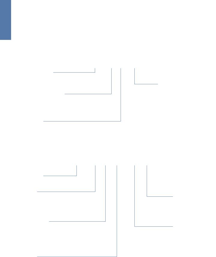
Bus Voltage:
If we assume a sine wave drive with a phase advance ϕ (degrees) and full conduction, the minimum bus voltage (see Fig. 1) is:
Vb1 = 2.4 (Volts)
Vb2 = Ke•Vm
Vb3 = 1.225•Rm,hot x Irms
Vb4 = 7.6953•L•Irms•Vm/Pitch
av = ARCTANGENT (Vb4/Vb3)
Vlr = Vb32 + Vb42
Vbre = Vb2 + Vlr•COS(av + ϕ)
Vbim = Vlr •SIN(av + ϕ)
V |
bus |
= V |
b1 |
+ |
V |
bre |
2 + Vbim2 |
|
|
|
|
|
Note: If there is no Phase advance take ϕ=0°.
Figure 1:
VB4
VBUS |
VLR |
|
|
|
VB3 |
|
VB2 |
VB1
Thermal Considerations:
|
|
|
|
|
|
Units |
|
|
|
|
|
SI |
English |
∆θ - Coil increase of temperature |
°C |
°F |
||||
Rth - Thermal Resistance |
°C/W |
°F/W |
||||
Km - Motor Constant |
N/ W |
lbf/ W |
||||
Pout - Output Power |
W |
W |
||||
Coil Temperature rise |
|
|
||||
∆θ = Rth•(Frms/Km)2 |
|
|
||||
Resistance of Coil hot (copper) |
|
|
||||
Rm,hot = Rambient (234.5 + θhot) |
|
|
||||
|
(234.5 + θhot) |
|
|
|
||
Power Losses |
|
|
||||
Plrms = ∆θ/Rth = (θhot - θambient) |
|
|
||||
|
|
Rth |
|
|
|
|
Output Power |
|
|
||||
Pout(max) = Fam•Vm |
|
|
||||
Example: In above example with: |
|
|
||||
Rth = 1.61 °C/W |
|
|
||||
Km = 4.7 N/ W, |
|
|
||||
Coil Temperature rise: ∆θ = 1.61•(23.19/4.7)2= 39.2 °C
Power Losses Pl = 39.2/1.61 = 24.34 Watts
Max output Power Pout(max) = 57 Watts.
The Use of the Motor Constant Km:
Cognizance of the heat load being generated by the linear motor is an important consideration in the application of any linear motor. Linear motors are direct drive devices, typically mounted very close to the moving load. Therefore, any heat generated by the linear motor needs to be managed to avoid affecting the process or workpiece that the moving load is carrying. The motor constant Km is a powerful parameter that can
be used to determine this heat load. Km equals:
Km = |
F |
where the RMS force F is in Newtons, |
|
Pc |
|||
|
the RMS heat load Pc is in watts |
||
|
|
||
|
|
and Km is in units of N/ W |
G N I Z I S N O I T A C I L P P A
w w w. k o l l m o r g e n . c o m |
75 |
|
|
|
|
G N I Z I S N O I T A C I L P P A
Application Sizing
The motor constant, KM, allows us to determine motor performance capabilities such as shown in the following two examples. In the first example, we use KM to calculate, for a given force, how many watts of generated heat are dissipated by the motorís coil assembly. In the
second, we use KM to determine the maximum RMS force developed by the motor when the dissipated power is limited to some value.
1. An application requires a continuous thrust force of 200 Newtons. The IC11-050 ironcore motor is a good candidate, having a continuous force rating of 276 Newtons and a KM of 32.0 N/W. Therefore, since resistance rises 1.405 times at 130°C from the ambient value at 25°C, and since resistance is the square root denominator of KM, we must write our equation as follows,
Force = |
KM |
Power (dissipated) |
|
Factor |
|
|
|
|
200 = |
32.0 |
Watts |
|
1.405 |
|
|
|
Watts = 54.9
This value of watts is the power or heat generated by the motor. It is interesting to note that for the same application, a larger IC11-100 ironcore motor, with a KM of 49.1 N/ W, would dissipate only 23.3 watts for the same force, F.
2. The same application requires that no more than 45 watts are to be dissipated by the motor into the surrounding structure and environment. What is the maximum RMS force that the IC11-050 motor may produce while not exceeding this power limit?
Maximum RMS Force = |
32.0 |
45 = 181 N |
|
1.405 |
|||
|
|
Continuous Force Fc as a Function of
Ambient Temperature
In our data sheets the continuous rated force Fc is the RMS force that the motor can supply continuously 100% of the time, assuming the ambient temperature is 25 degrees C and with the coils achieving a maximum temperature of 130 degrees C. At higher (or lower) ambient temperatures, the Fc of the motor must be adjusted by a factor that is determined by the following equation:
Factor = |
(130 -θAmb ) |
|
105 |
||
|
where θAmb = Ambient Temperature
This factor vs. ambient temperature works out as:
5 °C |
10 |
15 |
20 |
25 |
30 |
35 |
40 |
45 |
|
|
|
|
|
|
|
|
|
1.091 |
1.069 |
1.047 |
1.024 |
1 |
0.976 |
0.951 |
0.926 |
0.900 |
|
|
|
|
|
|
|
|
|
Therefore, if the motor delivers no more than 181 N of thrust force on an RMS basis, then this same motor will not dissipate more than 45 watts.
76 |
K O L L M O R G E N |
|
|
|
|
Application SizingWorksheet
Customer: |
Project Name: |
Contact: |
Axis Name: |
Telephone: |
Prepared by: |
fax: |
E-Mail: |
Move
Axis Orientation |
|
|
|
horizontal |
vertical |
|
||||||||
Typical Move |
|
|
|
mm |
in |
|
||||||||
Typical Travel Time |
|
|
|
mm |
in |
|
||||||||
Typical Move Time |
|
|
|
seconds |
|
|
||||||||
Maximum Speed |
|
|
|
meters/sec |
inches/sec |
|
||||||||
Minimum Speed |
|
|
|
meters/sec |
inches/sec |
|
||||||||
Max. Acceleration |
|
|
|
meters/sec2 |
inches/sec2 |
g |
||||||||
or Accel/Decel Time |
|
|
seconds |
|
|
|||||||||
Dwell Time |
|
|
|
seconds |
|
|
||||||||
More Profile |
|
|
trapezoidal |
triangular |
S-curve |
|
||||||||
Loads
Friction Coefficient
Max Load Mass |
|
kg |
lb |
||
Thrust Force |
|
N |
lbf |
||
Is this thrust present during Accel/Decel? |
|
Yes |
No |
||
Precision
Repeatability |
|
μm |
inch |
||
Absolute Accuracy |
|
μm |
inch |
||
Resolution |
|
μm |
inch |
||
Encoder Feedback
Signal Period |
|
|
|
μm |
|
|
|
Resolution |
|
|
|
lines/mm |
lines/in |
||
Electronic Interpolation |
|
Yes |
No |
If Yes, Muliplication Factor: |
|||
Environment
Ambient Temperature |
|
°C |
°F |
|
||||
Max Permissible Temperature Rise |
|
°C |
°F |
|
||||
Clean Room Environment |
|
Yes |
No |
If Yes Class: |
||||
Is Water or Air Cooling Permissible? |
|
Yes |
No |
|
||||
Vacuum? |
|
Yes |
No |
Pressure: |
||||
Amplifier & Power Supply
Max Voltage |
|
|
|
VDC |
|
||
Max Current |
|
|
|
Amps |
|
||
Power Supply |
|
|
Single Phase |
Three Phase |
|||
|
|
|
Voltage |
|
V |
50 Hz |
60 Hz |
w w w. k o l l m o r g e n . c o m |
|
|
|
|
|||
T E E H S K R O W G N I Z I S N O I T A C I L P P A
77

E R U T A L C N E M O N L E D O M
Model Nomenclature
High Flex Cable Numbering System
M1C – 01
High Flex Motor Cable
M = Motor
Wire Size
1C = 18 AWG for AKD 3/6 Amp amplifiers 2C = 14 AWG for AKD 12 Amp amplifiers * 3C = 12 AWG for AKD 24 Amp amplifiers *
Length in meters
01 |
= |
1 meter |
03 |
= |
3 meters |
06 |
= |
6 meters |
09 |
= |
9 meters |
12 |
= |
12 meters |
15 |
= |
15 meters |
Example: M1C - 06
High flex motor cable, terminated with connectors at motor and amplifier ends, 18 AWG, for 3 or 6 Amp AKD.
H1C – 01
High Flex Hall Effect Cable |
Length in meters |
||
H1C = Hall Effect |
01 |
= |
1 meter |
|
03 |
= |
3 meters |
Example: H1C - 06 |
06 |
= |
6 meters |
High flex Hall Effect cable, terminated with connectors at |
09 |
= |
9 meters |
motor and amplifier ends. |
12 |
= |
12 meters |
|
15 |
= |
15 meters |
T1C – 01
High Flex Thermal Cable |
Length in meters |
||
T1C = Thermal |
01 |
= |
1 meter |
T2C = Thermal (S300, S600) |
03 |
= |
3 meters |
|
06 |
= |
6 meters |
Example: T1C - 06 |
09 |
= |
9 meters |
High flex Thermal cable, terminated with |
12 |
= |
12 meters |
connectors at motor and amplifier ends. |
15 |
= |
15 meters |
* For application assistance regarding cable selection for these and other higher current rated amplifiers, contact a Kollmorgen Customer Support representative.
78 |
K O L L M O R G E N |
|
|
|
|
Coil Model Number Description
Coil Type
IL = Ironless
ICD = Low Profile Ironcore
IC = Ironcore
Coil Series
06 = 06 Series Ironless
12 = 12 Series Ironless
18 = 18 Series Ironless
24 = 24 Series Ironless
05 = 05 Series ICD
10 = 10 Series ICD
11 = 11 Series Ironcore
22 = 22 Series Ironcore
33 = 33 Series Ironcore
44 = 44 Series Ironcore
Magnetic Way Width (mm)
030 = 30mm
050 = 50mm
075 = 75mm
100 = 100mm
150 = 150mm (IC only)
200 = 200mm (IC only)
Winding Code
A1
A2 |
|
|
“Y” Windings |
||||
A3 |
|
||||||
|
|
||||||
A4 |
|
|
|
|
see performance specifications |
||
|
|
|
|||||
A5 |
|
|
|
|
|
|
|
|
|
|
|
|
|||
A6 |
|
|
“ ” Windings |
||||
A7 |
|
|
|
||||
|
|
|
|||||
A8 |
|
|
|
|
|||
|
|
|
|
||||
IL 06 030 A1 AC TR XX
 Termination Option Px or Cx
Px = Cable with Connector:
Configuration (P1) includes 400 mm (16”) shielded cable with connector.
P1 = 400 mm (16")
P2 = 200 mm (8")
P3 = 100 mm (4")
P4 = 1200 mm (48")
Cx = Motor cable and thermal cable with flying leads: C1 = 400 mm (16")
C2 = 200 mm (8")
C3 = 100 mm (4")
C4 = 1200 mm (48")
Thermal Protection Option
TS = Thermostat (IC only)
TR = Thermistor
If No Thermal Protection, leave blank.
Cooling Option (IC Only)
AC - Integral Cooling
If No Cooling, leave blank
Example: IL06030A1P1
Ironless 6 Series motor coil, 30 mm width, A1 winding designation terminated with 16” cable with connector.
Hall Effect Assembly Model Number Description
HDIL 100 XX
Hall Effect 
HDIL = Digital for Ironless (Microswitch SS461A)
HDIC = Digital for Ironcore (Microswitch SS461A)
Winding Code
100 (A1, A2, A3, A4)
200 (A5, A6, A7, A8)
Example: HDIL100P1
Hall effect assembly with digital outputs for Ironless motor terminated with 16” cable with connector.
Termination Option
Px - Cable with Connector:
Configuration (P1) includes 400 mm (16”) shielded cable with connector.
(lengths as above)
Cx - flying leads (lengths as above)
E R U T A L C N E M O N L E D O M
w w w. k o l l m o r g e n . c o m |
79 |
|
|
|
|
E N I G N E N O I T A C I L P P A G N I R E E N O I T O M
Model Nomenclature
Magnetic Way Model Number Description
MW 030 L 0128 001
Magnet Way Type
MW = Ironless
MCD = ICD
MC = Ironcore
Magnet Way Width (mm)
030 = 30mm |
100 |
= 100mm |
050 = 50mm |
150 |
= 150mm (IC only) |
075 = 75mm |
200 |
= 200mm (IC only) |
L = Low Profile
(30 & 50 mm Ironless only)
For standard Assemblies or Ironcore, leave blank.
 Magnet Way Cover (Ironcore only)
(Leave blank for Ironless or no cover)
Magnet Assembly Way Length (mm)
0064 = 64mm
0128 = 128mm
0256 = 256mm
0512 = 512mm
Example: MW0300128
Ironless magnet way, 30 mm magnet width, 128 mm assembly length.
AKD Servo Drive
AKD – B 003 06 – NA AN- 0000
AKD Series
Version
B = Base drive
P = Position indexer (motion tasking)
Current Rating
003 = 3 Amp
006 = 6 Amp
012 = 12 Amp
024 = 24 Amp
Voltage
06 = 120/240 Vac 1Ø/3Ø
 Variants
0000 = Standard
Connectivity
AN = Analog command
CN = CANopen
EC = EtherCAT
SQ = SynqNet
Extension
NA = Without extensions
Note: Options shown in bold blue text are considered standard.
80 |
K O L L M O R G E N |
|
|
|
|