

Linear Engine / DDL_Selection_Guide_en-EN_revA
.pdfRated Perfomance |
Symbol |
Units |
|
IC33-100 |
|
|
IC33-150 |
|
|
IC33-200 |
|
|
Peak Force |
Fp |
N |
|
3152 |
|
|
4724 |
|
|
6306 |
|
|
lbf |
|
709 |
|
|
1063 |
|
|
1418 |
|
|||
|
|
|
|
|
|
|
|
|||||
Continuous Force @ Tmax (1) |
Fc |
N |
|
2593 |
|
|
3849 |
|
|
5135 |
|
|
lbf |
|
583 |
|
|
865 |
|
|
1154 |
|
|||
|
|
|
|
|
|
|
|
|||||
Motor Constant @ 25°C |
Km |
N/√W |
|
76.5 |
|
|
96.9 |
|
|
114 |
|
|
Max. Cont. Power Dissipation |
Pc |
W |
|
2188 |
|
|
3000 |
|
|
3889 |
|
|
|
|
Electrical Specifications (2) |
|
|
|
|
|
|
||||
|
|
Winding Code |
A1 |
A3 |
A5 |
A1 |
A3 |
A5 |
A1 |
A3 |
A5 |
|
Peak Current |
lp |
Arms |
13.8 |
41.4 |
23.9 |
13.8 |
41.4 |
23.9 |
13.8 |
41.4 |
23.9 |
|
Continuous Current @Tmax |
lc |
Arms |
9.9 |
29.7 |
17.1 |
9.8 |
29.3 |
16.9 |
9.8 |
29.5 |
17.0 |
|
Elextrical Resistance |
Rm |
Ohms L-L |
10.6 |
1.2 |
3.5 |
14.9 |
1.7 |
5.0 |
19.1 |
2.1 |
6.4 |
|
@ 25°C±10% |
||||||||||||
|
|
|
|
|
|
|
|
|
|
|
||
Electrical Inductance ±20% |
L |
mH L-L |
96.2 |
10.7 |
32.1 |
143 |
15.9 |
47.7 |
190 |
21.1 |
63.3 |
|
Back EMF Constant |
Ke |
Vpeak/m/s L-L |
249 |
82.9 |
144 |
373 |
124 |
215 |
497 |
166 |
287 |
|
@ 25°C±10% |
Vpeak/in/sec L-L |
6.32 |
2.11 |
3.65 |
9.47 |
3.16 |
5.47 |
12.6 |
4.21 |
7.30 |
||
|
||||||||||||
Force Constant |
Kf |
N/Arms |
304 |
102 |
176 |
457 |
152 |
264 |
609 |
203 |
352 |
|
@ 25°C±10% |
lbf/Arms |
68.5 |
22.8 |
39.5 |
103 |
34.2 |
59.3 |
137 |
45.7 |
79.1 |
||
|
||||||||||||
|
|
Mechanical Specifications |
|
|
|
|
|
|
||||
Coil Assembly Mass ±15% |
Mc |
kg |
|
18.9 |
|
|
27.3 |
|
|
35.7 |
|
|
lbs |
|
41.7 |
|
|
60.2 |
|
|
78.7 |
|
|||
|
|
|
|
|
|
|
|
|||||
Magnetic Way Type |
|
|
|
MC100 |
|
|
MC150 |
|
|
MC200 |
|
|
Magnetic Way Mass ±15% |
Mw |
kg/m |
|
12.7 |
|
|
20.7 |
|
|
26.8 |
|
|
lb/in |
|
0.71 |
|
|
1.16 |
|
|
1.50 |
|
|||
|
|
|
|
|
|
|
|
|||||
|
|
Figures of Merit and Additional Data |
|
|
|
|
|
|||||
Electrical Time Constant |
Te |
ms |
|
9.1 |
|
|
9.6 |
|
|
9.9 |
|
|
Max.Theoretical Acceleration (3) |
Amax |
g’s |
|
20.2 |
|
|
21.0 |
|
|
21.4 |
|
|
Magnetic Attraction |
Fa |
kN |
|
14.7 |
|
|
22.1 |
|
|
29.4 |
|
|
lbf |
|
3305 |
|
|
4957 |
|
|
6609 |
|
|||
|
|
|
|
|
|
|
|
|||||
Thermal Resistance (4) |
Rth |
°C/Watt |
|
0.048 |
|
|
0.035 |
|
|
0.027 |
|
|
(coils to external structure) |
|
|
|
|
|
|
||||||
|
|
|
|
|
|
|
|
|
|
|
||
Max. Allowable Coil Temp. (4) |
Tmax |
°C |
|
130 |
|
|
130 |
|
|
130 |
|
|
Notes:
1.The motor continuous rated force is measured with the motor coils achieving the motor maximum allowable temperature Tmax.
2.Alternate windings can be made available. Please consult the Kollmorgen Customer Support for design options.
3.Maximum theoretical acceleration is based on the motors peak force and the motor mass alone. Limitations due to such factors as the additional mass of the load, the bearing type and design, the shock rating of the feedback, the peak current available from the amplifier etc. must be considered to determine the achievable acceleration in each application.
4.Please see our application sizing pages in the back of this guide for more details on sizing and thermal considerations.
A T A D E C N A M R O F R E P 3 3 C I
w w w. k o l l m o r g e n . c o m |
61 |
|
|
|
|
S G N I W A R D E N I L T U O 3 3 C I
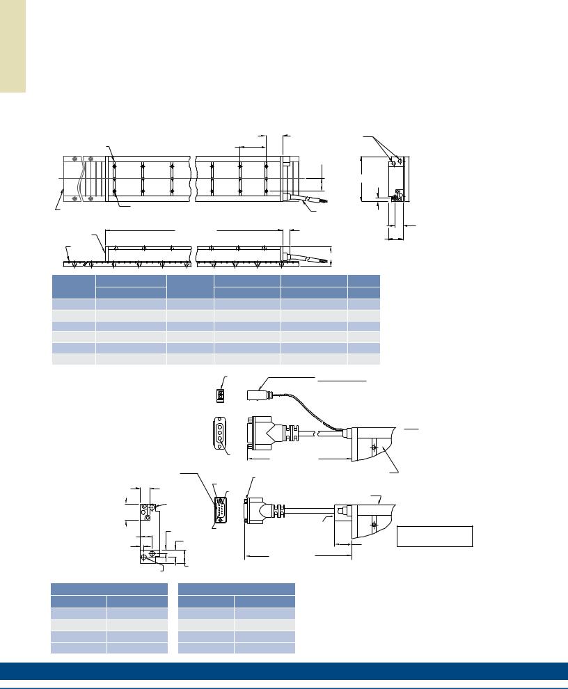
IC33 Outline Drawings |
|
|
|
|||
Ironcore Water-Cooled Motors Series |
|
|
|
|
|
|
|
|
|
51.1 |
OPTIONAL COOLING |
|
|
|
|
75.0 |
(2.012) |
|
|
|
MOUNTING BAR |
|
(SEE OPTIONS BELOW) |
|
|
||
|
(2.953) |
|
|
|
|
|
7 PER MOTOR |
|
6 PL. |
|
"C" DISTANCE BETWEEN |
|
|
|
|
|
|
MOUNTING HOLES |
|
|
|
|
|
|
(SEE PAGE 69) |
|
|
|
|
|
|
"A" |
11.9 |
|
|
|
|
|
(.469) |
||
|
|
|
|
|
|
|
OPTIONAL STAINLESS |
M5 X 0.8 X 8 DP. |
|
|
FOR MOTOR CABLE |
|
|
"N" NUMBER OF HOLES |
|
|
|
|
||
STEEL MAGNET COVER |
PER MOUNTING BAR |
|
|
AND HALL EFFECT MTG. |
|
|
|
552. ±2 |
.6 |
|
SEE OPTIONS BELOW |
|
|
|
|
19.1 |
|
|
||
COIL ASSEMBLY |
(21.740 ±.024) |
|
|
|
||
|
(.750) |
|
|
|||
|
|
|
43.3 REF |
|||
|
|
|
|
|
||
MAGNET |
|
|
|
|
|
|
WAY REF |
|
|
|
"B" |
|
|
|
|
|
|
|
|
|
Resultant airgap = 0.9mm (.036) nominal (0.5mm (.020”) minimum) when components are set up to dimension “B” in table below. (Please refer to installation manual for more detail)
22.7
(.894)
Motor Coil |
Coil Width |
Cooled |
Dim "B" |
Dim "B" |
# Holes |
|
Type |
"A" |
without Cover |
w/ Magnet Cover |
"N" |
||
|
||||||
IC33-030 |
65.0 (2.559) ± 1.0 (.04) |
ICXX-030 |
58.3±0.1 (2.295±.004) |
58.6±0.1 (2.307±.004) |
2 |
|
IC33-050 |
85.0 (3.346) ± 1.0 (.04) |
ICXX-050 |
58.3±0.1 (2.295±.004) |
58.6±0.1 (2.307±.004) |
2 |
|
IC33-075 |
110.0 (4.331) ± 1.0 (.04) |
ICXX-075 |
58.3±0.1 (2.295±.004) |
58.6±0.1 (2.307±.004) |
3 |
|
IC33-100 |
135.0 (5.315) ± 1.0 (.04) |
ICXX-100 |
58.3±0.1 (2.295±.004) |
58.6±0.1 (2.307±.004) |
3 |
|
IC33-150 |
185.0 (7.283) ± 1.0 (.06) |
ICXX-150 |
60.3±0.1 (2.374±.004) |
60.6±0.1 (2.386±.004) |
5 |
|
IC33-200 |
235.0 (9.252) ± 1.0 (.06) |
ICXX-200 |
60.3±0.1 (2.374±.004) |
60.6±0.1 (2.386±.004) |
6 |
Notes:
1.Dimensions in mm (inches)
2.Tolerances unless otherwise specified: no decimal place ±0.8 (0.3)
X decimal place ±0.1 (.004)
XX decimal place ±0.05 (0.002)
Termination and Hall Effect Options |
|
|
PIN1 |
|
2 PIN - MALE CONNECTOR |
|
|
|
|
|
|
THERMAL PROTECTION CONNECTOR: |
|
|
|
|
|
1 |
|
FREE HANGING RECEPTACLE |
|
|
|
THERMAL |
|
MOLEX P/N 43025-0200 |
|
|
|
|
2 |
|
||
|
|
|
|
2 FEMALE TERMINALS |
||
|
|
|
|
|
|
|
|
|
|
|
|
|
MOLEX P/N 43030-0010 |
|
|
|
MOTOR |
|
|
|
HALL EFFECT CONNECTOR OPTION: |
|
|
|
|||
POSITRONIC P/N: MD9M2000Z |
|
|
|
|
|
|
9 PIN, MALE |
|
|
|
PIN1 |
STANDARD LENGTH, |
|
MATING CONNECTOR REFERENCE: |
|
|
|
|||
|
|
SEE TABLE |
|
|||
POSITRONIC P/N: MD9F2000X |
|
|
|
|
||
|
|
|
|
|
||
SEE WIRE TABLE, PAGE 70 |
|
|
|
|
#4-40 JACKNUT (2) |
COIL ASSEMBLY REF |
|
|
|
|
|
|
|
|
|
|
|
PIN 5 |
(REMOVABLE FOR BULKHEAD MOUNTING) |
|
14.6 |
|
|
|
|
|
|
|
|
|
PIN 9 |
|
|
|
(.575) |
|
|
|
|
COIL ASSEMBLY REF |
|
|
|
|
|
|
||
|
|
|
|
|
|
|
MOTOR CABLE |
|
|
|
|||
31.7 |
|
|
HALL |
|
|
|
(1.25) |
|
|
EFFECT |
|
|
|
|
|
|
|
PIN 1 |
HALL EFFECT ASSEMBLY |
|
26.4 |
8.4 (.331) |
|
|
|
||
|
|
|
|
|||
|
|
|
|
|
|
|
(1.038) |
|
16.2 (.637) |
|
|
|
|
|
|
|
|
26.8 |
||
7.8 |
|
|
|
|
|
|
|
|
|
|
|
(1.055) |
|
(.308) |
|
|
|
|
|
|
|
|
|
|
STANDARD LENGTH, |
MAX. |
|
|
|
|
|
|
||
|
|
|
|
|
|
|
|
|
|
32.0 (1.260) |
|
SEE TABLE |
|
COOLING OPTION: |
|
|
|
|
|
|
|
|
|
|
|
|
|
1/8-27 NPT (FEMALE) 2 PL. |
|
|
|
|
|
|
MATING CONNECTOR REFERENCE:
MOLEX "MICRO-FIT 3.0" PLUG: 43020-0201
MALE TERMINALS: 43031-0010 SEE WIRE TABLE, PAGE 70
MOTOR CONNECTOR:
POSITRONIC P/N: CBD3W3M0000Z 3 PIN, MALE SHELL, SIZE 2
MALE CONTACTS:
POSITRONIC P/N: MS40--D 3 REMOVABLE MALE CONTACTS, SIZE 8
MATING CONNECTOR REFERENCE:
POSITRONIC P/N: CBD3W3F0000X 3 FEMALE SOCKETS, SOLDER TYPE, SIZE 8, POSITRONIC P/N: FS40--D
SEE WIRE TABLE, PAGE 70
HALL EFFECT MASS
W/P* CONNECTOR: .07 KG (.15 LB) MAX W/C* CABLE: .03 KG (.07 LB) MAX
Connector Option
Connector |
Length |
|
P1 |
400 (16) |
|
P2 |
200 (8) |
|
P3 |
100 |
(4) |
P4 |
1200 |
(48) |
Flying Lead Option
Leads |
Length |
|
C1 |
400 (16) |
|
C2 |
200 (8) |
|
C3 |
100 |
(4) |
C4 |
1200 |
(48) |
Note:
Cables exiting motor and hall effects are not dynamic flex cables. For high life flex
extension cables, see page 72
62 |
K O L L M O R G E N |

Notes
S G N I W A R D E N I L T U O 3 3 C I
w w w. k o l l m o r g e n . c o m |
63 |
|
|
|
|
A T A D E C N A M R O F R E P 4 4 C I
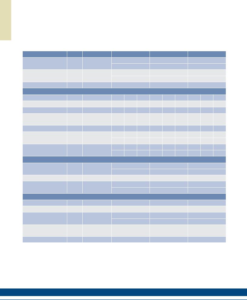
IC44PerformanceData
Ironcore Water-Cooled Motors Series
Rated Perfomance |
Symbol |
Units |
|
IC44-030 |
|
|
IC44-050 |
|
|
IC44-075 |
|
|
Peak Force |
Fp |
N |
|
1260 |
|
|
2101 |
|
|
3154 |
|
|
lbf |
|
283 |
|
|
472 |
|
|
709 |
|
|||
|
|
|
|
|
|
|
|
|||||
Continuous Force @ Tmax (1) |
Fc |
N |
|
1036 |
|
|
1711 |
|
|
2568 |
|
|
lbf |
|
233 |
|
|
385 |
|
|
577 |
|
|||
|
|
|
|
|
|
|
|
|||||
Motor Constant @ 25°C |
Km |
N/√W |
|
39.9 |
|
|
56.8 |
|
|
74.0 |
|
|
|
|
Electrical Specifications (2) |
|
|
|
|
|
|
||||
|
|
Winding Code |
A1 |
A2 |
A3 |
A1 |
A2 |
A3 |
A1 |
A2 |
A3 |
|
Peak Current |
lp |
Arms |
13.8 |
27.6 |
55.2 |
13.8 |
27.6 |
55.2 |
13.8 |
27.6 |
55.2 |
|
Continuous Current @Tmax |
lc |
Arms |
9.9 |
19.7 |
39.5 |
9.8 |
19.6 |
39.1 |
9.8 |
19.5 |
39.1 |
|
Elextrical Resistance |
Rm |
Ohms L-L |
6.2 |
1.6 |
0.39 |
8.5 |
2.1 |
0.53 |
11.3 |
2.8 |
0.71 |
|
@ 25°C±10% |
||||||||||||
|
|
|
|
|
|
|
|
|
|
|
||
Electrical Inductance ±20% |
L |
mH L-L |
41.3 |
10.3 |
2.6 |
66.1 |
16.5 |
4.1 |
97.3 |
24.3 |
6.1 |
|
Back EMF Constant |
Ke |
Vpeak/m/s L-L |
99.4 |
49.7 |
24.8 |
166 |
82.9 |
41.4 |
249 |
124 |
62.2 |
|
@ 25°C±10% |
Vpeak/in/sec L-L |
2.52 |
1.26 |
0.63 |
4.21 |
2.11 |
1.05 |
6.32 |
3.16 |
1.58 |
||
|
||||||||||||
Force Constant |
Kf |
N/Arms |
122 |
60.9 |
30.4 |
203 |
102 |
50.8 |
305 |
152 |
76.2 |
|
@ 25°C±10% |
lbf/Arms |
27.4 |
13.7 |
6.8 |
45.6 |
22.8 |
11.4 |
68.5 |
34.2 |
17.1 |
||
|
||||||||||||
|
|
Mechanical Specifications |
|
|
|
|
|
|
||||
Coil Assembly Mass ±15% |
Mc |
kg |
|
9.6 |
|
|
13.9 |
|
|
19.2 |
|
|
lbs |
|
21.2 |
|
|
30.6 |
|
|
42.3 |
|
|||
|
|
|
|
|
|
|
|
|||||
Magnetic Way Type |
|
|
|
MC030 |
|
|
MC050 |
|
|
MC075 |
|
|
Magnetic Way Mass ±15% |
Mw |
kg/m |
|
5.4 |
|
|
7.5 |
|
|
10.1 |
|
|
lb/in |
|
0.30 |
|
|
0.42 |
|
|
0.56 |
|
|||
|
|
|
|
|
|
|
|
|||||
|
|
Figures of Merit and Additional Data |
|
|
|
|
|
|||||
Electrical Time Constant |
Te |
ms |
|
6.7 |
|
|
7.8 |
|
|
8.6 |
|
|
Max.Theoretical Acceleration (3) |
Amax |
g’s |
|
15.9 |
|
|
18.3 |
|
|
19.9 |
|
|
Magnetic Attraction |
Fa |
kN |
|
5.9 |
|
|
9.8 |
|
|
14.7 |
|
|
lbf |
|
1322 |
|
|
2203 |
|
|
3305 |
|
|||
|
|
|
|
|
|
|
|
|||||
Thermal Resistance (4) |
Rth |
°C/Watt |
|
0.082 |
|
|
0.061 |
|
|
0.046 |
|
|
(coils to external structure) |
|
|
|
|
|
|
||||||
|
|
|
|
|
|
|
|
|
|
|
||
Max. Allowable Coil Temp. (4) |
Tmax |
°C |
|
130 |
|
|
130 |
|
|
130 |
|
|
Notes:
1.The motor continuous rated force is measured with the motor coils achieving the motor maximum allowable temperature Tmax.
2.Alternate windings can be made available. Please consult the Kollmorgen Customer Support for design options.
3.Maximum theoretical acceleration is based on the motors peak force and the motor mass alone. Limitations due to such factors as the additional mass of the load, the bearing type and design, the shock rating of the feedback, the peak current available from the amplifier etc. must be considered to determine the achievable acceleration in each application.
4.Please see our application sizing pages in the back of this guide for more details on sizing and thermal considerations.
64 |
K O L L M O R G E N |

Rated Perfomance |
Symbol |
Units |
|
IC44-100 |
|
|
IC44-150 |
|
|
IC44-200 |
|
|
Peak Force |
Fp |
N |
|
4202 |
|
|
6303 |
|
|
8407 |
|
|
lbf |
|
945 |
|
|
1417 |
|
|
1890 |
|
|||
|
|
|
|
|
|
|
|
|||||
Continuous Force @ Tmax (1) |
Fc |
N |
|
3457 |
|
|
5133 |
|
|
6916 |
|
|
lbf |
|
777 |
|
|
1154 |
|
|
1555 |
|
|||
|
|
|
|
|
|
|
|
|||||
Motor Constant @ 25°C |
Km |
N/√W |
|
88.3 |
|
|
112 |
|
|
132 |
|
|
|
|
Electrical Specifications (2) |
|
|
|
|
|
|
||||
|
|
Winding Code |
A1 |
A2 |
A3 |
A1 |
A2 |
A3 |
A1 |
A2 |
A3 |
|
Peak Current |
lp |
Arms |
13.8 |
27.5 |
55.1 |
13.8 |
27.6 |
55.3 |
13.8 |
27.6 |
55.2 |
|
Continuous Current @Tmax |
lc |
Arms |
9.9 |
19.8 |
39.5 |
9.8 |
19.6 |
39.2 |
9.9 |
19.8 |
39.6 |
|
Elextrical Resistance |
Rm |
Ohms L-L |
14.1 |
3.5 |
0.88 |
19.8 |
5.0 |
1.2 |
25.5 |
6.4 |
1.6 |
|
@ 25°C±10% |
||||||||||||
|
|
|
|
|
|
|
|
|
|
|
||
Electrical Inductance ±20% |
L |
mH L-L |
128 |
32.1 |
8.0 |
191 |
47.7 |
11.9 |
253 |
63.3 |
15.8 |
|
Back EMF Constant |
Ke |
Vpeak/m/s L-L |
331 |
166 |
82.9 |
497 |
249 |
124 |
663 |
332 |
166 |
|
@ 25°C±10% |
Vpeak/in/sec L-L |
8.42 |
4.21 |
2.11 |
12.6 |
6.32 |
3.16 |
16.8 |
8.42 |
4.21 |
||
|
||||||||||||
Force Constant |
Kf |
N/Arms |
406 |
203 |
102 |
609 |
305 |
152 |
812 |
406 |
203 |
|
@ 25°C±10% |
lbf/Arms |
91.3 |
45.6 |
22.8 |
137 |
68.5 |
34.2 |
183 |
91.3 |
45.7 |
||
|
||||||||||||
|
|
Mechanical Specifications |
|
|
|
|
|
|
||||
Coil Assembly Mass ±15% |
Mc |
kg |
|
25.0 |
|
|
36.2 |
|
|
47.4 |
|
|
lbs |
|
55.1 |
|
|
79.8 |
|
|
104 |
|
|||
|
|
|
|
|
|
|
|
|||||
Magnetic Way Type |
|
|
|
MC100 |
|
|
MC150 |
|
|
MC200 |
|
|
Magnetic Way Mass ±15% |
Mw |
kg/m |
|
12.7 |
|
|
20.7 |
|
|
26.8 |
|
|
lb/in |
|
0.71 |
|
|
1.16 |
|
|
1.50 |
|
|||
|
|
|
|
|
|
|
|
|||||
|
|
Figures of Merit and Additional Data |
|
|
|
|
|
|||||
Electrical Time Constant |
Te |
ms |
|
9.1 |
|
|
9.6 |
|
|
9.9 |
|
|
Max.Theoretical Acceleration (3) |
Amax |
g’s |
|
20.4 |
|
|
21.1 |
|
|
21.5 |
|
|
Magnetic Attraction |
Fa |
kN |
|
19.6 |
|
|
29.4 |
|
|
39.4 |
|
|
lbf |
|
4406 |
|
|
6609 |
|
|
8855 |
|
|||
|
|
|
|
|
|
|
|
|||||
Thermal Resistance (4) |
Rth |
°C/Watt |
|
0.036 |
|
|
0.026 |
|
|
0.020 |
|
|
(coils to external structure) |
|
|
|
|
|
|
||||||
|
|
|
|
|
|
|
|
|
|
|
||
Max. Allowable Coil Temp. (4) |
Tmax |
°C |
|
130 |
|
|
130 |
|
|
130 |
|
|
Notes:
1.The motor continuous rated force is measured with the motor coils achieving the motor maximum allowable temperature Tmax.
2.Alternate windings can be made available. Please consult the Kollmorgen Customer Support for design options.
3.Maximum theoretical acceleration is based on the motors peak force and the motor mass alone. Limitations due to such factors as the additional mass of the load, the bearing type and design, the shock rating of the feedback, the peak current available from the amplifier etc. must be considered to determine the achievable acceleration in each application.
4.Please see our application sizing pages in the back of this guide for more details on sizing and thermal considerations.
A T A D E C N A M R O F R E P 4 4 C I
w w w. k o l l m o r g e n . c o m |
65 |
|
|
|
|
S G N I W A R D E N I L T U O 4 4 C I
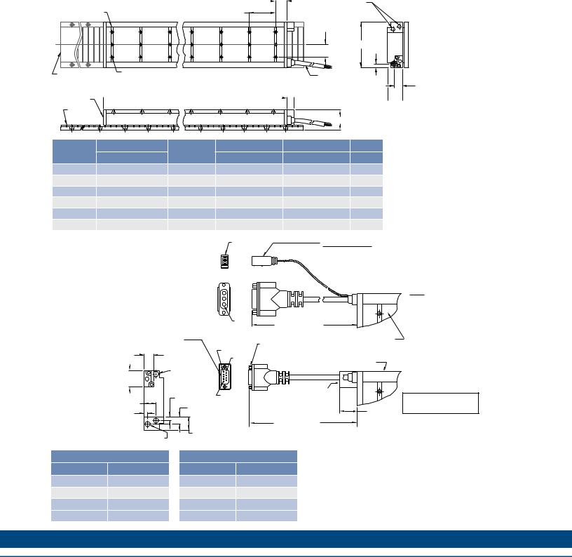
 IC44OutlineDrawings
Ironcore Water-Cooled Motors Series
MOUNTING BAR |
75.0 |
10 PER MOTOR |
(2.953) |
9 PL.
OPTIONAL STAINLESS |
M5 X 0.8 X 8 DP. |
|
"N" NUMBER OF HOLES |
||
STEEL MAGNET COVER |
||
PER MOUNTING BAR |
||
|
26.6 |
|
|
|
OPTIONAL COOLING |
(1.047) |
|
|
|
(SEE OPTIONS BELOW) |
|
|
|
"C" DISTANCE BETWEEN |
|
|
MOUNTING HOLES |
|
|
(SEE PAGE 69) |
|
|
"A" |
11.9 |
|
(.469) |
||
|
||
FOR MOTOR CABLE |
|
|
AND HALL EFFECT MTG. |
|
|
SEE OPTIONS BELOW |
|
728. ±2 .6
COIL ASSEMBLY  (28.669 ±.024)
 19.1 43.3 REF
 (.750)
MAGNET WAY REF
"B"
Resultant airgap = 0.9mm (.036) nominal (0.5mm (.020”) minimum) when components are set up to dimension “B” in table below. (Please refer to installation manual for more detail)
22.7
(.894)
Motor Coil |
Coil Width |
Cooled |
Dim "B" |
Dim "B" |
# Holes |
|
Type |
"A" |
without Cover |
w/ Magnet Cover |
"N" |
||
|
||||||
IC44-030 |
65.0 (2.559) ± 1.0 (.04) |
ICXX-030 |
58.3±0.1 (2.295±.004) |
58.6±0.1 (2.307±.004) |
2 |
|
IC44-050 |
85.0 (3.346) ± 1.0 (.04) |
ICXX-050 |
58.3±0.1 (2.295±.004) |
58.6±0.1 (2.307±.004) |
2 |
|
IC44-075 |
110.0 (4.331) ± 1.0 (.04) |
ICXX-075 |
58.3±0.1 (2.295±.004) |
58.6±0.1 (2.307±.004) |
3 |
|
IC44-100 |
135.0 (5.315) ± 1.0 (.04) |
ICXX-100 |
58.3±0.1 (2.295±.004) |
58.6±0.1 (2.307±.004) |
3 |
|
IC44-150 |
185.0 (7.283) ± 1.0 (.06) |
ICXX-150 |
60.3±0.1 (2.374±.004) |
60.6±0.1 (2.386±.004) |
5 |
|
IC44-200 |
235.0 (9.252) ± 1.0 (.06) |
ICXX-200 |
60.3±0.1 (2.374±.004) |
60.6±0.1 (2.386±.004) |
6 |
Notes:
1.Dimensions in mm (inches)
2.Tolerances unless otherwise specified: no decimal place ±0.8 (0.3)
X decimal place ±0.1 (.004)
XX decimal place ±0.05 (0.002)
Termination and Hall Effect Options |
|
|
PIN1 |
|
2 PIN - MALE CONNECTOR |
|
|
|
|
|
|
THERMAL PROTECTION CONNECTOR: |
|
|
|
|
|
1 |
|
FREE HANGING RECEPTACLE |
|
|
|
THERMAL |
|
MOLEX P/N 43025-0200 |
|
|
|
|
2 |
|
||
|
|
|
|
2 FEMALE TERMINALS |
||
|
|
|
|
|
|
|
|
|
|
|
|
|
MOLEX P/N 43030-0010 |
|
|
|
MOTOR |
|
|
|
HALL EFFECT CONNECTOR OPTION: |
|
|
|
|||
POSITRONIC P/N: MD9M2000Z |
|
|
|
|
|
|
9 PIN, MALE |
|
|
|
PIN1 |
STANDARD LENGTH, |
|
MATING CONNECTOR REFERENCE: |
|
|
|
|||
|
|
SEE TABLE |
|
|||
POSITRONIC P/N: MD9F2000X |
|
|
|
|
||
|
|
|
|
|
||
SEE WIRE TABLE, PAGE 70 |
|
|
|
|
#4-40 JACKNUT (2) |
COIL ASSEMBLY REF |
|
|
|
|
|
|
|
|
|
|
|
PIN 5 |
(REMOVABLE FOR BULKHEAD MOUNTING) |
|
14.6 |
|
|
|
|
|
|
|
|
|
PIN 9 |
|
|
|
(.575) |
|
|
|
|
COIL ASSEMBLY REF |
|
|
|
|
|
|
||
|
|
|
|
|
|
|
MOTOR CABLE |
|
|
|
|||
31.7 |
|
|
HALL |
|
|
|
(1.25) |
|
|
EFFECT |
|
|
|
|
|
|
|
PIN 1 |
HALL EFFECT ASSEMBLY |
|
26.4 |
8.4 (.331) |
|
|
|
||
|
|
|
|
|||
|
|
|
|
|
|
|
(1.038) |
|
16.2 (.637) |
|
|
|
|
|
|
|
|
26.8 |
||
7.8 |
|
|
|
|
|
|
|
|
|
|
|
(1.055) |
|
(.308) |
|
|
|
|
|
|
|
|
|
|
STANDARD LENGTH, |
MAX. |
|
|
|
|
|
|
||
|
|
|
|
|
|
|
|
|
|
32.0 (1.260) |
|
SEE TABLE |
|
COOLING OPTION: |
|
|
|
|
|
|
|
|
|
|
|
|
|
1/8-27 NPT (FEMALE) 2 PL. |
|
|
|
|
|
|
MATING CONNECTOR REFERENCE:
MOLEX "MICRO-FIT 3.0" PLUG: 43020-0201
MALE TERMINALS: 43031-0010 SEE WIRE TABLE, PAGE 70
MOTOR CONNECTOR:
POSITRONIC P/N: CBD3W3M0000Z 3 PIN, MALE SHELL, SIZE 2
MALE CONTACTS:
POSITRONIC P/N: MS40--D 3 REMOVABLE MALE CONTACTS, SIZE 8
MATING CONNECTOR REFERENCE:
POSITRONIC P/N: CBD3W3F0000X 3 FEMALE SOCKETS, SOLDER TYPE, SIZE 8, POSITRONIC P/N: FS40--D
SEE WIRE TABLE, PAGE 70
HALL EFFECT MASS
W/P* CONNECTOR: .07 KG (.15 LB) MAX W/C* CABLE: .03 KG (.07 LB) MAX
Connector Option
Connector |
Length |
|
P1 |
400 (16) |
|
P2 |
200 (8) |
|
P3 |
100 |
(4) |
P4 |
1200 |
(48) |
Flying Lead Option
Leads |
Length |
|
C1 |
400 (16) |
|
C2 |
200 (8) |
|
C3 |
100 |
(4) |
C4 |
1200 |
(48) |
Note:
Cables exiting motor and hall effects are not dynamic flex cables. For high life flex
extension cables, see page 72
66 |
K O L L M O R G E N |

Notes
S G N I W A R D E N I L T U O 4 4 C I
w w w. k o l l m o r g e n . c o m |
67 |
|
|
|
|
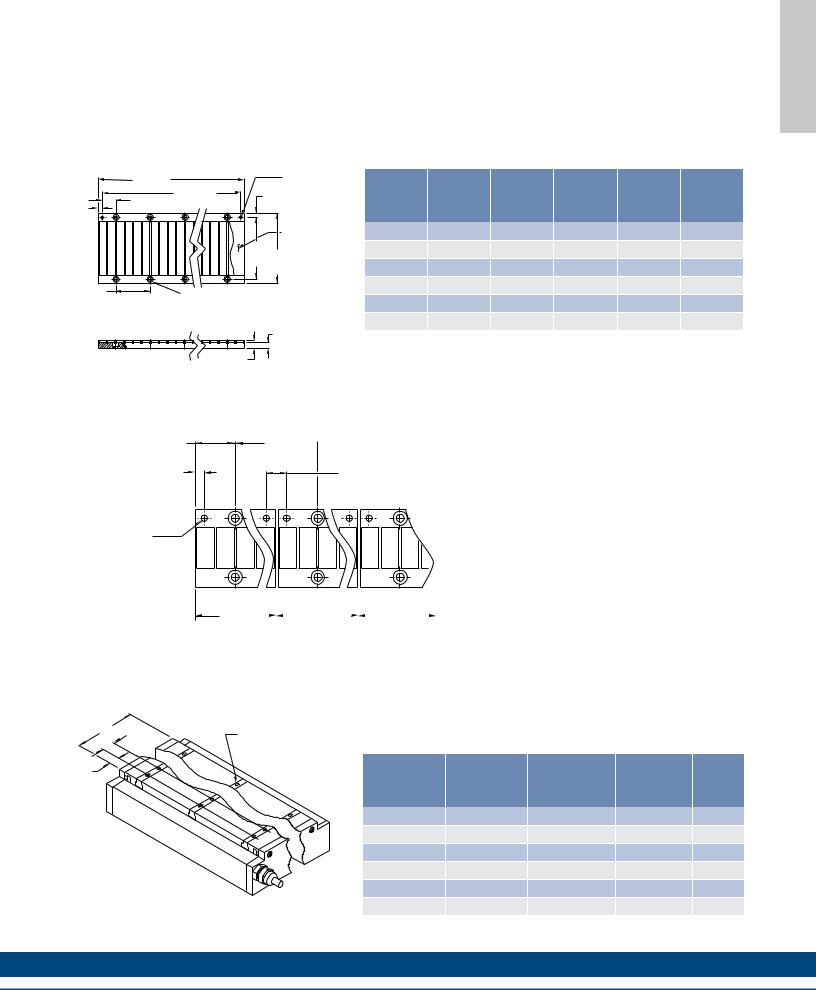
Ironcore MagnetWays
I |
MCxxx-0064 |
|
|
|
R |
|
|
||
O |
|
|
|
|
N |
|
|
|
|
C |
|
|
|
|
O |
|
|
63.3 ±.15 |
|
R |
50.0 ±.05 |
|
(2.492 ±.006) |
|
(1.968 ±.002) |
|
|
|
|
E |
|
|
|
|
|
|
|
|
|
|
25.0 |
|
|
Ø5.110-5.135 (.201-.202) |
M |
|
|
THRU 2 PL. MARKED "A" |
|
(.984) |
|
|
||
|
7.5 |
FOR RECOMMENDED |
||
A |
|
|
5mm M6 LOCATING PINS |
|
6.65 |
|
(.295) |
||
|
|
|||
G |
(.262) |
A |
A |
|
|
|
|||
N |
|
|
|
OPTIONAL |
E |
|
|
|
STAINLESS STEEL |
|
|
|
MAGNET COVER |
|
T |
|
|
|
|
|
|
"W2" |
|
|
|
|
|
|
|
W |
|
|
|
"W" |
S Y A |
|
|
|
|
|
|
|
|
|
|
|
Ø6.6 (.260) THRU C'BORE Ø11.0 (.433) X 6.2 (.246) DP. |
|
|
2 PL. LOCATED AS SHOWN. RECOMMENDED MOUNTING HARDWARE: |
"J" |
"H" |
• M6 SOC. HD. CAP DIN 912 (1/4" SOC. HD. CAP SCREW) |
|
Magnet assembiles are modular and can be installed in multiples of same or alternate lengths. Standard lengths are shown below.
Magnetic |
Assembly |
Mounting |
|
"H" |
"H" |
Way |
Width |
Hole Width |
"J" |
With |
Without |
Type |
"W" |
"W2" |
|
Cover |
Cover |
MC030-0064 |
60.0 (2.362) |
45.0 (1.772) |
10.0 (.394) |
14.4 (.556) |
14.1 (.555) |
MC050-0064 |
80.0 (3.150) |
65.0 (2.560) |
10.0 (.394) |
14.4 (.556) |
14.1 (.555) |
MC075-0064 |
105.0 (4.134) |
90.0 (3.544) |
10.0 (.394) |
14.4 (.556) |
14.1 (.555) |
MC100-0064 |
130.0 (5.118) |
115.0 (4.528) |
10.0 (.394) |
14.4 (.556) |
14.1 (.555) |
MC150-0064 |
180.0 (7.087) |
165.0 (6.496) |
12.0 (.472) |
16.4 (.645) |
16.1 (.634) |
MC200-0064 |
230.0 (9.055) |
215.0 (8.464) |
12.0 (.472) |
16.4 (.645) |
16.1 (.634) |
Dimensions in mm (in)
MCxxx-0128
|
|
|
|
|
|
|
127.3 |
±.15 |
|
Ø5.110-5.135 (.201-.202) |
|||||||||||||||||||
|
|
|
|
|
|
|
(5.012 |
±.006) |
|
|
|
|
|
|
|
|
THRU 2 PL. MARKED "A" |
||||||||||||
|
|
|
|
|
|
|
|
|
|
|
|
|
|
|
FOR RECOMMENDED |
||||||||||||||
6.65 |
|
|
|
|
|
|
|
|
|
|
|
|
|
|
|
|
|
|
|
|
|
|
|||||||
|
|
|
|
|
|
|
|
|
|
|
|
|
|
|
|
|
|
|
|
|
|
5mm M6 LOCATING PINS |
|||||||
(.262) |
|
|
|
114.0 |
±.05 |
|
|
|
|
|
|
|
|
|
|
|
|
|
|||||||||||
|
|
|
|
|
|
|
(4.488 |
±.002) |
|
|
|
|
|
|
|
|
|
7.5 |
|
|
|
||||||||
25.0 |
|
|
|
|
|
|
|
|
|
|
|
|
|
|
|
|
|
|
|
|
|
|
|||||||
(.984) |
|
|
|
|
|
|
|
|
|
|
|
|
|
|
|
|
|
(.295) |
|
|
|
||||||||
|
|
|
|
|
|
|
A |
|
|
|
|
A |
|
|
|
|
|
|
|
OPTIONAL |
|||||||||
|
|
|
|
|
|
|
|
|
|
|
|
|
|
|
|
|
|
|
|
|
|
|
|
|
|
|
|
|
|
|
|
|
|
|
|
|
|
|
|
|
|
|
|
|
|
|
|
|
|
|
|
|
|
|
|
|
|
|
STAINLESS |
|
|
|
|
|
|
|
|
|
|
|
|
|
|
|
|
|
|
|
|
|
|
"W2" ±.10 |
|
|
STEEL |
||||
|
|
|
|
|
|
|
|
|
|
|
|
|
|
|
|
|
|
|
|
|
|
|
MAGNET |
||||||
|
|
|
|
|
|
|
|
|
|
|
|
|
|
|
|
|
|
|
|
|
|
|
(.004) |
|
|
COVER |
|||
|
|
|
|
|
|
|
|
|
|
|
|
|
|
|
|
|
|
|
|
|
|
|
|||||||
|
|
|
|
|
|
|
|
|
|
|
|
|
|
|
|
|
|
|
|
|
|
|
|
|
|
|
|
|
|
|
|
|
|
|
|
|
|
|
|
|
|
|
|
|
|
|
|
|
|
|
|
|
|
|
|
"W" |
±.3 |
||
|
|
|
|
|
|
|
|
|
|
|
|
|
|
|
|
|
|
|
|
|
|
|
|
|
|
|
|
|
(.012) |
|
|
|
|
|
|
|
|
|
|
|
|
|
|
|
|
|
|
|
|
|
|
|
|
|
|
|
|
|
|
|
|
|
|
|
|
|
|
|
|
|
|
|
|
64.0 |
|
|
|
|
|
|
Ø6.6 (.260) THRU |
|
|||||||
|
|
|
|
|
|
|
|
|
|
|
|
|
|
|
|
|
|
|
|
C'BORE Ø11.0 (.433) X 6.2 (.246) DP. 4 PL. LOCATED AS SHOWN |
|||||||||
|
|
|
|
|
(2.520) |
|
|
|
|
|
|
RECOMMENDED MOUNTING HARDWARE: • M6 SOC. HD. CAP |
|||||||||||||||||
|
|
|
|
|
|
|
|
|
|
|
|
|
|
2 PL. |
|
|
|
|
|||||||||||
|
|
|
|
|
|
|
|
|
|
|
|
|
|
|
|
|
|
DIN 912 (1/4" SOC. HD. CAP SCREW) |
|||||||||||
|
|
|
|
|
|
|
|
|
|
|
|
|
|
|
|
|
|
|
|
|
|
||||||||
|
|
|
|
|
|
|
|
|
|
|
|
|
|
|
|
|
|
|
|
|
|
|
|
|
|
|
|
|
|
|
|
|
|
|
|
|
|
|
|
|
|
|
|
|
|
|
|
|
|
|
|
|
|
|
|
|
|
|
|
"J" |
|
|
"H" ±.2 (.008) |
|
|
|
|
|
|
|
|
|
|
|
|
|
|
|
|||||||||||
|
|
|
|
|
|
|
|
|
|
|
|
|
|
|
|
||||||||||||||
Magnetic |
Assembly |
Mounting |
|
"H" |
"H" |
Way |
Width |
Hole Width |
"J" |
With |
Without |
Type |
"W" |
"W2" |
|
Cover |
Cover |
MC030-0128 |
60.0 (2.362) |
45.0 (1.772) |
10.0 (.394) |
14.4 (.556) |
14.1 (.555) |
MC050-0128 |
80.0 (3.150) |
65.0 (2.560) |
10.0 (.394) |
14.4 (.556) |
14.1 (.555) |
MC075-0128 |
105.0 (4.134) |
90.0 (3.544) |
10.0 (.394) |
14.4 (.556) |
14.1 (.555) |
MC100-0128 |
130.0 (5.118) |
115.0 (4.528) |
10.0 (.394) |
14.4 (.556) |
14.1 (.555) |
MC150-0128 |
180.0 (7.087) |
165.0 (6.496) |
12.0 (.472) |
16.4 (.645) |
16.1 (.634) |
MC200-0128 |
230.0 (9.055) |
215.0 (8.464) |
12.0 (.472) |
16.4 (.645) |
16.1 (.634) |
Dimensions in mm (in)
MCxxx-0256 |
|
|
|
|
|
|
|
|
|
|
|
|
|
|
Ø5.110-5.135 (.201-.202) THRU 2 PL. MARKED "A" |
|
|
|
|
|
|
|
|
|
|
FOR RECOMMENDED 5mm M6 LOCATING PINS |
|
|
|
|
|
|
|
255.3 |
±.15 |
|
|
Magnetic |
Assembly |
Mounting |
|
"H" |
"H" |
|
(10.051 |
±.006) |
±.05 |
|
|
|||||
|
25.0 |
242.0 |
|
|
|
|
|
|
|
|
6.65 |
(9.528 |
±.002) |
7.5 (.295) |
Way |
Width |
Hole Width |
"J" |
With |
Without |
|
(.984) |
|
|
|
|||||||
(.262) |
A |
|
|
A |
Type |
"W" |
"W2" |
|
Cover |
Cover |
|
|
|
|
|||||||
|
|
|
|
"W2" |
|
|||||
|
|
|
|
MC030-0256 |
60.0 (2.362) |
45.0 (1.772) |
10.0 (.394) |
14.4 (.556) |
14.1 (.555) |
|
|
|
|
|
±.10 |
||||||
|
|
|
|
(.004) |
|
|
|
|
|
|
|
|
|
|
"W" |
MC050-0256 |
80.0 (3.150) |
65.0 (2.560) |
10.0 (.394) |
14.4 (.556) |
14.1 (.555) |
|
|
|
|
±.3 |
|
|
|
|
|
|
|
|
|
|
(.012) |
MC075-0256 |
105.0 (4.134) |
90.0 (3.544) |
10.0 (.394) |
14.4 (.556) |
14.1 (.555) |
|
|
|
|
|
||||||
|
|
64.0 |
|
OPTIONAL |
MC100-0256 |
130.0 (5.118) |
115.0 (4.528) |
10.0 (.394) |
14.4 (.556) |
14.1 (.555) |
|
|
(2.520) |
|
STAINLESS |
|
|
|
|
|
|
|
|
6 PL. |
|
STEEL |
MC150-0256 |
180.0 (7.087) |
165.0 (6.496) |
12.0 (.472) |
16.4 (.645) |
16.1 (.634) |
|
|
|
|
MAGNET |
||||||
|
|
|
|
COVER |
MC200-0256 |
230.0 (9.055) |
215.0 (8.464) |
12.0 (.472) |
16.4 (.645) |
16.1 (.634) |
|
|
|
|
|
||||||
Ø6.6 (.260) THRU
C'BORE Ø11.0 (.433) X 6.2 (.246) DP. 8 PL. LOCATED AS SHOWN Dimensions in mm (in) RECOMMENDED MOUNTING HARDWARE: • M6 SOC. HD. CAP
DIN 912 (1/4" SOC. HD. CAP SCREW)
"J" "H" ±.2 (.008)
68 K O L L M O R G E N
MCxxx-0512 |
|
|
|
|
|
|
511.3 |
±.15 |
|
|
Ø5.110-5.135 (.201-.202) |
|
(20.130 ±.006) |
498.0 ±.05 |
|
THRU 2 PL. MARKED "A" |
|
|
|
|
|
FOR RECOMMENDED 5mm M6 |
|
|
|
|
(19.606 ±.002) |
7.5 |
|
|
25.0 |
|
LOCATING PINS |
||
|
|
|
(.295) |
|
|
6.65 |
(.984) |
|
|
|
|
|
|
|
|
||
(.262) |
|
|
A |
|
|
A |
|
|
|
|
|
|
|
|
|
|
OPTIONAL STAINLESS |
|
|
|
|
|
STEEL MAGNET COVER |
|
|
|
"W2" |
|
|
|
|
|
±.10 |
"W" |
|
|
|
|
(.004) |
±.3 |
|
|
|
|
|
(.012) |
|
64.0 |
Ø6.6 (.260) THRU |
|
(2.520) |
||
C'BORE Ø11.0 (.433) X 6.2 (.246) DP. |
||
14 PL. |
||
16 PL. LOCATED AS SHOWN |
RECOMMENDED MOUNTING HARDWARE:
• M6 SOC. HD. CAP DIN 912
(1/4" SOC. HD. CAP SCREW)
"J"
"H" ±.2 (.008)
Magnetic |
Assembly |
Mounting |
|
"H" |
"H" |
Way |
Width |
Hole Width |
"J" |
With |
Without |
Type |
"W" |
"W2" |
|
Cover |
Cover |
MC030-0512 |
60.0 (2.362) |
45.0 (1.772) |
10.0 (.394) |
14.4 (.556) |
14.1 (.555) |
MC050-0512 |
80.0 (3.150) |
65.0 (2.560) |
10.0 (.394) |
14.4 (.556) |
14.1 (.555) |
MC075-0512 |
105.0 (4.134) |
90.0 (3.544) |
10.0 (.394) |
14.4 (.556) |
14.1 (.555) |
MC100-0512 |
130.0 (5.118) |
115.0 (4.528) |
10.0 (.394) |
14.4 (.556) |
14.1 (.555) |
MC150-0512 |
180.0 (7.087) |
165.0 (6.496) |
12.0 (.472) |
16.4 (.645) |
16.1 (.634) |
MC200-0512 |
230.0 (9.055) |
215.0 (8.464) |
12.0 (.472) |
16.4 (.645) |
16.1 (.634) |
Dimensions in mm (in)
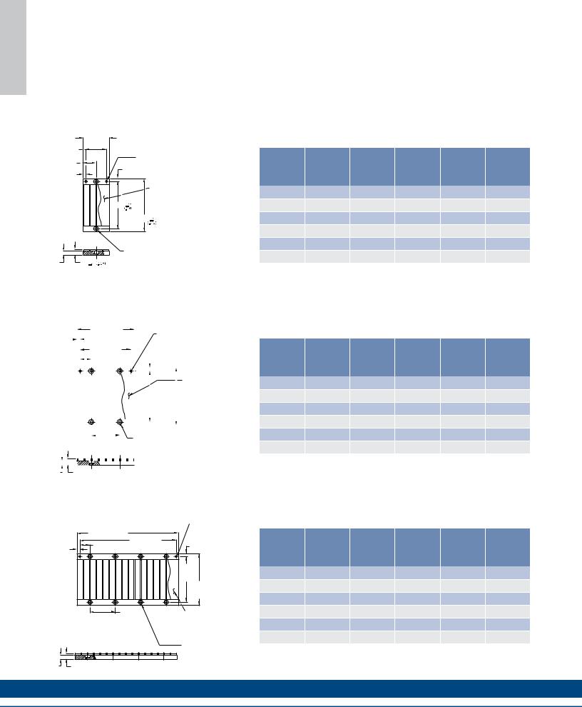
Typical Installation of Multiple Ironcore Magnet Assemblies
31.75
(1.250)
6.75
(.266)
PIN DATUM HOLES TO BE LOCATED ON
SAME SIDE TO ENSURE CORRECT A NORTH/SOUTH POLE ORIENTATION
64.0
(2.520)  TYP BOLT MTG.
14.00 (.551)
PIN LOC.
RECOMMENDED
PIN Ø5 M6
A |
A |
A |
A |
Magnet Way widths correspond to the mating coil assembly width. Magnet Way assemblies are modular and come in standard lengths: 64, 128, 256, 512 mm. Multiple magnet assemblies can be installed to obtain the desired length. Shown below is the method to mount multiple assemblies.
1ST |
|
2ND |
|
|
3RD |
|
RESULTANT GAP BETWEEN MAGNET |
||
MAGNET |
|
|
MAGNET |
|
|
|
MAGNET |
|
ASSEMBLIES FROM PROPER PIN |
|
|
|
|
|
|||||
ASSEMBLY |
|
ASSEMBLY |
|
|
ASSEMBLY |
|
LOCATION. DO NOT BUTT MAGNET |
||
|
|
|
|
|
|
|
|
|
ASSEMBLIES. |
Typical Mounting Bar Lengths & Mounting Holes Tabulation
"L" "C"
"S"
M5 X .8 X 8 DP. NUMBER OF HOLES PER BAR "N" WILL
VARY WITH MOTOR WIDTH
Magnetic |
Number |
Spacing |
Mounting |
|
Coil |
of Holes |
Between Holes |
Bar Length |
"S" |
Type |
"N" |
"C" |
"L" |
|
ICXX-030 |
2 |
16.0 (0.630) |
30 (1.18) |
7.0 (.276) |
ICXX-050 |
2 |
36.0 (1.417) |
50 (1.97) |
7.0 (.276) |
ICXX-075 |
3 |
32.0 (1.260) |
75 (2.95) |
5.5 (.217) |
ICXX-100 |
3 |
36.0 (1.417) |
100 (3.94) |
14.0 (.551) |
ICXX-150 |
5 |
32.0 (1.260) |
150 (5.91) |
11.0 (.433) |
ICXX-200 |
6 |
36.0 (1.417) |
200 (7.87) |
10.0 (.394) |
Dimensions in mm (in)
w w w. k o l l m o r g e n . c o m |
69 |
S Y A W T E N G A M E R O C N O R I

T U P T U O D N A G N I R I W
Wiring and Output
|
Motor Wire Table |
|
|
Hall Effect Wire Table |
Thermal Protection Wire Table |
|||||
SEE TABLE BELOW FOR AWG DIA |
|
26 AWG 6.0 DIA (.24") |
Thermistor 26 AWG 3.8 (.15") |
|||||||
|
Color or |
|
Pin |
|
|
|
|
|
Transition |
|
Pin Number |
Wire No. |
Function |
Number |
Color |
Function |
Pin |
Color |
|
Point |
|
1 |
Red |
ØA |
1 |
Gray |
+5 VDC |
1 |
Black/White |
120˚C (IC/ICD) |
||
2 |
White |
ØB |
2 |
Green |
S1 |
90˚C (IL) |
||||
|
|
|
||||||||
3 |
Black |
ØC |
3 |
Yellow |
S2 |
2 |
Black/White |
120˚C (IC/ICD) |
||
Connector Shell |
Grn/Yel |
GND |
4 |
Brown |
S3 |
90˚C (IL) |
||||
|
|
|
||||||||
Connector Shell |
Violet |
Shield |
5 |
White |
Return |
|
|
see note 2 |
||
|
|
|
Shell |
Shield |
Shield |
|
|
|||
|
|
|
|
|
|
|
||||
Notes: |
|
|
|
|
|
IL WIRE TABLE |
|
|
||
1. Ground and shield connection at shell: first make/last break |
|
|
|
|
|
|||||
2. TIC-X extender cable is shielded |
|
|
|
WINDING CODE |
AWG |
|
APPROX. CBL. DIA. |
|||
|
|
|
|
|
ALL (A1,A2,A3,A4) |
18 |
|
|
5.6mm (.22 IN) |
|
Motor BEMF phases A,B,C relative to Hall effect devices S1,S2,S3 with coil travel direction towards the motor output cable assembly exit as shown below.
ICD WIRE TABLE
WINDING CODE |
AWG |
APPROX. CBL. DIA. |
ALL (A1 - A4) |
22 |
5.1mm (.20 IN) |
IC WIRE TABLE NON-COOLED |
||
WINDING CODE |
AWG |
APPROX. CBL. DIA. |
A1 |
18 |
5.6mm (.22 IN) |
A2 |
18 |
5.8mm (.22 IN) |
A3 |
14 |
8.9mm (.27 IN) |
A5 |
18 |
5.8mm (.22 IN) |
A6 |
14 |
6.9mm (.27 IN) |
A7 |
10 |
7.9mm (.31 IN) |
IC WIRE TABLE COOLED (AC) |
||
WINDING CODE |
AWG |
APPROX. CBL. DIA. |
A1 |
18 |
5.6mm (.22 IN) |
A2 |
14 |
8.9mm (.27 IN) |
A3 |
10 |
7.9mm (.31 IN) |
A5 |
14 |
8.9mm (.27 IN) |
A6 |
12 |
7.9mm (.31 IN) |
COIL ASSEMBLY |
MAGNET WAY |
|
A |
MOTOR WINDING |
A |
|
|
|
CONFIGURATION WITH |
||
|
|
|
|
TRAVEL DIRECTION |
|
|
|
|
|
AS SHOWN |
|
|
COIL TRAVEL DIRECTION |
|
|
|
|
|
MOTOR OUTPUT |
C |
B |
C |
B |
Magnet pole pitch: |
CABLE |
|
|
|
|
|
|
|
|
|
Both Ironcore (IC) and Ironless (IL) feature the same pole pitch, which is 32 mm (360 electrical degrees).
Note:
1.The diagram above refers to both Ironless and Ironcore motors
70 |
K O L L M O R G E N |