

Linear Engine / DDL_Selection_Guide_en-EN_revA
.pdfRated Perfomance |
Symbol |
Units |
|
IC44-100 |
|
|
IC44-150 |
|
|
IC44-200 |
|
||||
Peak Force |
Fp |
N |
|
4192 |
|
|
6289 |
|
|
8388 |
|
||||
lbf |
|
942 |
|
|
1414 |
|
|
1885 |
|
||||||
|
|
|
|
|
|
|
|
||||||||
Continuous Force @ Tmax (1) |
Fc |
N |
|
2296 |
|
|
3445 |
|
|
4786 |
|
||||
lbf |
|
516 |
|
|
774 |
|
|
1076 |
|
||||||
|
|
|
|
|
|
|
|
||||||||
Motor Constant @ 25°C |
Km |
N/√W |
|
98.3 |
|
|
124 |
|
|
|
146 |
|
|||
|
|
Electrical Specifications (2) |
|
|
|
|
|
|
|
|
|||||
|
|
Winding Code |
A1 |
A2 |
A3 |
A7 |
A1 |
A2 |
A3 |
A7 |
A1 |
A2 |
A3 |
A7 |
|
Peak Current |
lp |
Arms |
11.1 |
22.1 |
44.1 |
76.4 |
11.1 |
22.1 |
44.1 |
76.4 |
11.1 |
22.1 |
44.1 |
76.4 |
|
Continuous Current @Tmax |
lc |
Arms |
4.8 |
9.5 |
19.0 |
33.0 |
4.8 |
9.6 |
19.2 |
33.2 |
5.0 |
10.0 |
20.0 |
34.6 |
|
ElextricalResistance |
Rm |
Ohms L-L |
17.6 |
4.4 |
1.1 |
0.37 |
24.7 |
6.2 |
1.5 |
0.51 |
31.8 |
8.0 |
2.0 |
0.66 |
|
@ 25°C±10% |
|||||||||||||||
|
|
|
|
|
|
|
|
|
|
|
|
|
|
||
Electrical Inductance ±20% |
L |
mh L-L |
208 |
52.1 |
13.0 |
4.3 |
309 |
77.4 |
19.3 |
6.4 |
410 |
103 |
25.7 |
8.6 |
|
Back EMF Constant |
Ke |
Vpeak/m/s L-L |
411 |
206 |
103 |
59.3 |
617 |
308 |
154 |
89.0 |
823 |
411 |
206 |
119 |
|
@25°C±10% |
Vpeak/in/sec L-L |
10.4 |
5.22 |
2.61 |
1.51 |
15.7 |
7.83 |
3.92 |
2.26 |
20.9 |
10.4 |
5.22 |
3.02 |
||
|
|||||||||||||||
Force Constant @ 25°C±10% |
Kf |
N/Arms |
504 |
252 |
126 |
72.7 |
755 |
378 |
189 |
109 |
1008 |
504 |
252 |
145 |
|
lbf/Arms |
113 |
56.6 |
28.3 |
16.3 |
170 |
84.9 |
42.5 |
24.5 |
227 |
113 |
56.6 |
32.7 |
|||
|
|
||||||||||||||
|
|
Mechanical Specifications |
|
|
|
|
|
|
|
|
|||||
Coil Assembly Mass ±15% |
Mc |
kg |
|
25.0 |
|
|
36.2 |
|
|
|
47.4 |
|
|||
lbs |
|
55.1 |
|
|
79.8 |
|
|
|
104 |
|
|||||
|
|
|
|
|
|
|
|
|
|||||||
Magnetic Way Type |
|
|
|
MC100 |
|
|
MC150 |
|
|
MC200 |
|
||||
Magnetic Way Mass ±15% |
Mw |
kg/m |
|
12.7 |
|
|
20.7 |
|
|
|
26.8 |
|
|||
lbs/in |
|
0.71 |
|
|
1.16 |
|
|
|
1.50 |
|
|||||
|
|
|
|
|
|
|
|
|
|||||||
|
|
Figures of Merit and Additional Data |
|
|
|
|
|
|
|
||||||
Electrical Time Constant |
Te |
ms |
|
11.8 |
|
|
12.5 |
|
|
|
12.9 |
|
|||
Max.Theoretical Acceleration(3) |
Amax |
g’s |
|
20.4 |
|
|
21.1 |
|
|
|
21.5 |
|
|||
Magnetic Attraction |
Fa |
kN |
|
19.6 |
|
|
29.4 |
|
|
|
39.4 |
|
|||
lbf |
|
4406 |
|
|
6609 |
|
|
8858 |
|
||||||
|
|
|
|
|
|
|
|
||||||||
Thermal Resistance |
Rth |
°C/Watt |
|
0.13 |
|
|
0.088 |
|
|
0.063 |
|
||||
(coils to external structure) |
|
|
|
|
|
|
|||||||||
|
|
|
|
|
|
|
|
|
|
|
|
|
|
||
Max. Allowable Coil Temp. (4) |
Tmax |
°C |
|
130 |
|
|
130 |
|
|
|
130 |
|
|||
Notes:
1.The motor continuous rated force is measured with the motor coils achieving the motor maximum allowable temperature Tmax.
2.Alternate windings can be made available. Please consult the Kollmorgen Customer Support for design options.
3.Maximum theoretical acceleration is based on the motors peak force and the motor mass alone. Limitations due to such factors as the additional mass of the load, the bearing type and design, the shock rating of the feedback, the peak current available from the amplifier etc. must be considered to determine the achievable acceleration in each application.
4.Please see our application sizing pages in the back of this guide for more details on sizing and thermal considerations.
A T A D E C N A M R O F R E P 4 4 C I
w w w. k o l l m o r g e n . c o m |
51 |
|
|
|
|
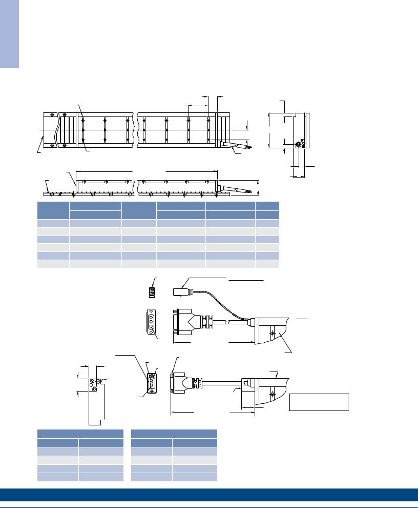
S G N I W A R D E N I L T U O S E I R E S 4 4 C I
IC44SeriesOutlineDrawings |
|
|
|
||||
Ironcore Non-Cooled Motors Series |
|
|
|
|
|
|
|
|
|
|
26.6 |
18.0 |
±.2 |
|
Resultant airgap = |
|
|
|
(1.047) |
|
0.9mm (.036) nominal |
||
MOUNTING BAR |
|
|
75.0 |
(.709 |
±.008) |
|
|
10 PER MOTOR |
|
|
(2.953) |
"C" DISTANCEEN BETWEEN |
|
(0.5mm (.020”) minimum) |
|
|
|
|
9 PL. |
|
|||
|
|
|
MOUNTING HOLES |
|
|
||
|
|
|
|
(SEE PAGE 69) |
|
|
when components are |
|
|
|
|
|
|
|
|
|
|
|
|
|
"A" |
11.9 |
set up to dimension “B” |
|
|
|
|
|
|
||
|
|
|
|
|
|
(.469) |
in table below. (Please |
|
|
|
|
|
|
|
|
OPTIONAL STAINLESS |
M5 X 0.8 X 8 DP. |
|
|
|
|
|
refer to installation |
|
|
FOR MOTOR CABLE |
|
manual for more detail) |
|||
"N" NUMBER OF HOLES |
|
|
|
||||
STEEL MAGNET COVER |
|
|
AND HALL EFFECT MTG. |
|
|||
|
|
|
BLE |
|
|
|
|
|
PER MOUNTING BAR |
|
|
MTG. |
|
|
|
|
|
|
|
SEE OPTIONS BELOW |
|
|
|
|
|
728. ±2 .6 |
ELOW |
|
|
22.7 |
|
COIL ASSEMBLY |
|
|
|
|
(.894) |
||
|
(28.669 |
±.024) |
|
|
|
||
MAGNET |
|
|
|
|
43.3 REF |
|
|
|
|
|
|
|
|
|
|
WAY REF |
|
|
|
"B" |
|
|
|
|
|
|
|
|
|
|
|
Motor Coil |
Coil Width |
Non-Cooled |
Dim "B" |
Dim "B" |
# Holes |
|
Type |
"A" |
without Cover |
w/ Magnet Cover |
"N" |
||
|
||||||
IC44-030 |
65.0 (2.559) ± 1.0 (.04) |
ICXX-030 |
58.3±0.1 (2.295±.004) |
58.6±0.1 (2.307±.004) |
2 |
|
IC44-050 |
85.0 (3.346) ± 1.0 (.04) |
ICXX-050 |
58.3±0.1 (2.295±.004) |
58.6±0.1 (2.307±.004) |
2 |
|
IC44-075 |
110.0 (4.331) ± 1.0 (.04) |
ICXX-075 |
58.3±0.1 (2.295±.004) |
58.6±0.1 (2.307±.004) |
3 |
|
IC44-100 |
135.0 (5.315) ± 1.0 (.04) |
ICXX-100 |
58.3±0.1 (2.295±.004) |
58.6±0.1 (2.307±.004) |
3 |
|
IC44-150 |
185.0 (7.283) ± 1.0 (.06) |
ICXX-150 |
60.3±0.1 (2.374±.004) |
60.6±0.1 (2.386±.004) |
5 |
|
IC44-200 |
235.0 (9.252) ± 1.0 (.06) |
ICXX-200 |
60.3±0.1 (2.374±.004) |
60.6±0.1 (2.386±.004) |
6 |
Notes:
1.Dimensions in mm (inches)
2.Tolerances unless otherwise specified: no decimal place ±0.8 (0.3)
X decimal place ±0.1 (.004)
XX decimal place ±0.05 (0.002)
Termination and Hall Effect Options |
|
PIN1 |
|
THERMAL PROTECTION CONNECTOR: |
||
|
|
|
|
|
|
2 PIN - MALE CONNECTOR |
|
|
|
1 |
|
|
FREE HANGING RECEPTACLE |
|
|
THERMAL |
|
|
MOLEX P/N 43025-0200 |
|
|
|
2 |
|
|
||
|
|
|
|
2 FEMALE TERMINALS |
||
|
|
|
|
|
|
|
|
|
|
|
|
|
MOLEX P/N 43030-0010 |
|
|
MOTOR |
|
|
|
|
HALL EFFECT CONNECTOR OPTION: |
|
|
|
|
|
|
POSITRONIC P/N: MD9M2000Z |
|
|
|
|
|
|
9 PIN, MALE |
|
|
|
PIN1 |
STANDARD LENGTH, |
|
MATING CONNECTOR REFERENCE: |
|
|
|
|
||
POSITRONIC P/N: MD9F2000X |
|
|
|
SEE TABLE |
|
|
SEE WIRE TABLE, PAGE 70 |
|
|
|
|
COIL ASSEMBLY REF |
|
|
|
|
#4-40 JACKNUT (2) |
|
||
|
|
|
|
|
|
|
|
|
|
PIN 5 |
|
(REMOVABLE FOR BULKHEAD MOUNTING) |
|
|
14.6 |
|
|
|
|
|
|
|
|
|
|
|
|
|
(.575) |
|
|
|
|
COIL ASSEMBLY REF |
|
|
|
|
|
|
|
|
MOTOR |
HALL |
|
|
|
|
31.7 |
CABLE |
|
|
|
|
|
EFFECT |
|
|
|
|
||
(1.25) |
|
|
|
|
|
|
|
|
|
|
|
|
|
|
|
PIN1 |
|
|
HALL EFFECT ASSEMBLY |
|
|
|
|
|
|
|
|
|
|
|
|
|
|
26.8 |
|
|
|
|
|
STANDARD LENGTH, |
(1.055) |
|
|
|
|
|
SEE TABLE |
MAX. |
MATING CONNECTOR REFERENCE:
MOLEX "MICRO-FIT 3.0" PLUG: 43020-0201
MALE TERMINALS: 43031-0010
SEE WIRE TABLE, PAGE 70
MOTOR CONNECTOR:
POSITRONIC P/N: CBD3W3M0000Z 3 PIN, MALE SHELL, SIZE 2
MALE CONTACTS:
POSITRONIC P/N: MS40--D 3 REMOVABLE MALE CONTACTS, SIZE 8
MATING CONNECTOR REFERENCE:
POSITRONIC P/N: CBD3W3F0000X 3 FEMALE SOCKETS, SOLDER TYPE, SIZE 8, POSITRONIC P/N: FS40--D
SEE WIRE TABLE, PAGE 70
HALL EFFECT MASS
W/P* CONNECTOR: .07 KG (.15 LB) MAX W/C* CABLE: .03 KG (.07 LB) MAX
Connector Option
Connector |
Length |
|
P1 |
400 (16) |
|
P2 |
200 (8) |
|
P3 |
100 |
(4) |
P4 |
1200 |
(48) |
Flying Lead Option
Leads |
Length |
|
C1 |
400 (16) |
|
C2 |
200 (8) |
|
C3 |
100 |
(4) |
C4 |
1200 |
(48) |
Note:
Cables exiting motor and hall effects are not dynamic flex cables. For high life flex
extension cables, see page 72
52 |
K O L L M O R G E N |

Notes
S G N I W A R D E N I L T U O S E I R E S 4 4 C I
w w w. k o l l m o r g e n . c o m |
53 |
|
|
|
|
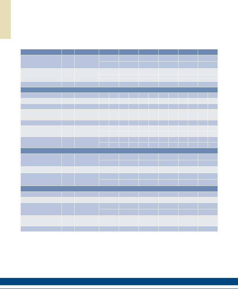
A T A D E C N A M R O F R E P 1 1 C I
IC11 Performance Data
Ironcore Water-Cooled Motors Series
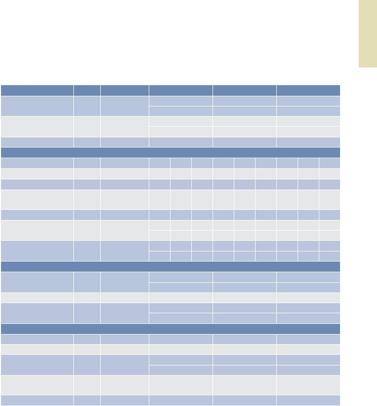
Rated Perfomance |
Symbol |
Units |
IC11-030 |
IC11-050 |
IC11-075 |
IC11-100 |
IC11-150 |
IC11-200 |
|||||||
Peak Force |
Fp |
N |
315 |
525 |
798 |
|
1051 |
1576 |
2102 |
||||||
lbf |
70.8 |
118 |
|
179 |
|
236 |
354 |
473 |
|||||||
|
|
|
|
||||||||||||
Continuous Force @ Tmax (1) |
Fc |
N |
254 |
432 |
649 |
864 |
1285 |
1712 |
|||||||
lbf |
57.1 |
97.1 |
146 |
|
194 |
|
289 |
385 |
|||||||
|
|
|
|
||||||||||||
Motor Constant @ 25°C |
Km |
N/√W |
19.3 |
28.6 |
37.3 |
45.0 |
55.7 |
65.7 |
|||||||
|
|
Electrical Specifications (2) |
|
|
|
|
|
|
|
||||||
|
|
Winding Code |
A1 |
A5 |
A1 |
A5 |
A1 |
A5 |
A1 |
A5 |
A1 |
A5 |
A1 |
A5 |
|
Peak Current |
lp |
Arms |
13.8 |
23.9 |
13.8 |
23.9 |
13.8 |
23.9 |
13.8 |
23.9 |
13.8 |
23.9 |
13.8 |
23.9 |
|
Continuous Current @Tmax |
lc |
Arms |
9.7 |
16.9 |
9.9 |
17.2 |
9.9 |
17.1 |
9.9 |
17.2 |
9.8 |
17.0 |
9.8 |
17.0 |
|
ElextricalResistance |
Rm |
Ohms L-L |
1.6 |
0.53 |
2.1 |
0.70 |
2.8 |
0.93 |
3.5 |
1.2 |
5.0 |
1.7 |
6.4 |
2.1 |
|
@ 25°C±10% |
|||||||||||||||
|
|
|
|
|
|
|
|
|
|
|
|
|
|
||
Electrical Inductance ±20% |
L |
mh L-L |
10.3 |
3.4 |
16.5 |
5.5 |
24.4 |
8.1 |
32.1 |
10.7 |
47.7 |
15.9 |
63.3 |
21.1 |
|
Back EMF Constant |
Ke |
Vpeak/m/s L-L |
24.8 |
14.3 |
41.4 |
23.9 |
62.2 |
35.9 |
82.9 |
47.8 |
124 |
71.7 |
166 |
95.7 |
|
@25°C±10% |
Vpeak/in/sec L-L |
0.63 |
0.36 |
1.05 |
0.61 |
1.58 |
0.91 |
2.11 |
1.22 |
3.16 |
1.82 |
4.21 |
2.43 |
||
|
|||||||||||||||
Force Constant @ 25°C±10% |
Kf |
N/Arms |
30.4 |
17.6 |
50.7 |
29.3 |
76.2 |
44.0 |
102 |
58.6 |
152 |
87.9 |
203 |
117 |
|
lbf/Arms |
6.8 |
3.9 |
11.4 |
6.6 |
17.1 |
9.9 |
22.8 |
13.2 |
34.2 |
19.8 |
45.7 |
26.4 |
|||
|
|
||||||||||||||
|
|
|
Mechanical Specifications |
|
|
|
|
|
|
|
|
||||
Coil Assembly Mass ±15% |
Mc |
kg |
|
2.5 |
3.6 |
|
5.0 |
|
6.5 |
|
|
9.4 |
12.3 |
||
lbs |
|
5.5 |
7.9 |
|
11.0 |
14.3 |
20.7 |
27.1 |
|||||||
|
|
|
|
||||||||||||
Magnetic Way Type |
|
|
MC030 |
MC050 |
MC075 |
MC100 |
MC150 |
MC200 |
|||||||
Magnetic Way Mass ±15% |
Mw |
kg/m |
|
5.4 |
7.5 |
|
10.1 |
12.7 |
20.7 |
26.8 |
|||||
lbs/in |
0.30 |
0.42 |
0.56 |
0.71 |
1.16 |
1.50 |
|||||||||
|
|
||||||||||||||
|
|
Figures of Merit and Additional Data |
|
|
|
|
|
|
|
||||||
Electrical TimeConstant |
Te |
ms |
|
6.4 |
7.9 |
|
8.7 |
|
9.2 |
|
|
9.5 |
|
9.9 |
|
Max.Theoretical Acceleration(3) |
Amax |
g’s |
15.3 |
17.7 |
19.2 |
19.6 |
20.3 |
20.7 |
|||||||
Magnetic Attraction |
Fa |
kN |
|
1.4 |
2.4 |
|
3.7 |
|
4.9 |
|
|
7.3 |
|
9.9 |
|
lbf |
324 |
546 |
821 |
1102 |
1639 |
2214 |
|||||||||
|
|
||||||||||||||
Thermal Resistance (4) |
Rth |
°C/Watt |
0.33 |
0.24 |
0.18 |
0.15 |
0.10 |
0.081 |
|||||||
(coils to external structure) |
|||||||||||||||
|
|
|
|
|
|
|
|
|
|
|
|
|
|
||
Max. Allowable Coil Temp. (4) |
Tmax |
°C |
130 |
130 |
|
130 |
|
130 |
|
130 |
130 |
||||
Notes:
1.The motor continuous rated force is measured with the motor coils achieving the motor maximum allowable temperature Tmax.
2.Alternate windings can be made available. Please consult the Kollmorgen Customer Support for design options.
3.Maximum theoretical acceleration is based on the motors peak force and the motor mass alone. Limitations due to such factors as the additional mass of the load, the bearing type and design, the shock rating of the feedback, the peak current available from the amplifier etc. must be considered to determine the achievable acceleration in each application.
4.Please see our application sizing pages in the back of this guide for more details on sizing and thermal considerations.
54 |
K O L L M O R G E N |
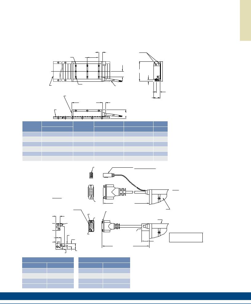
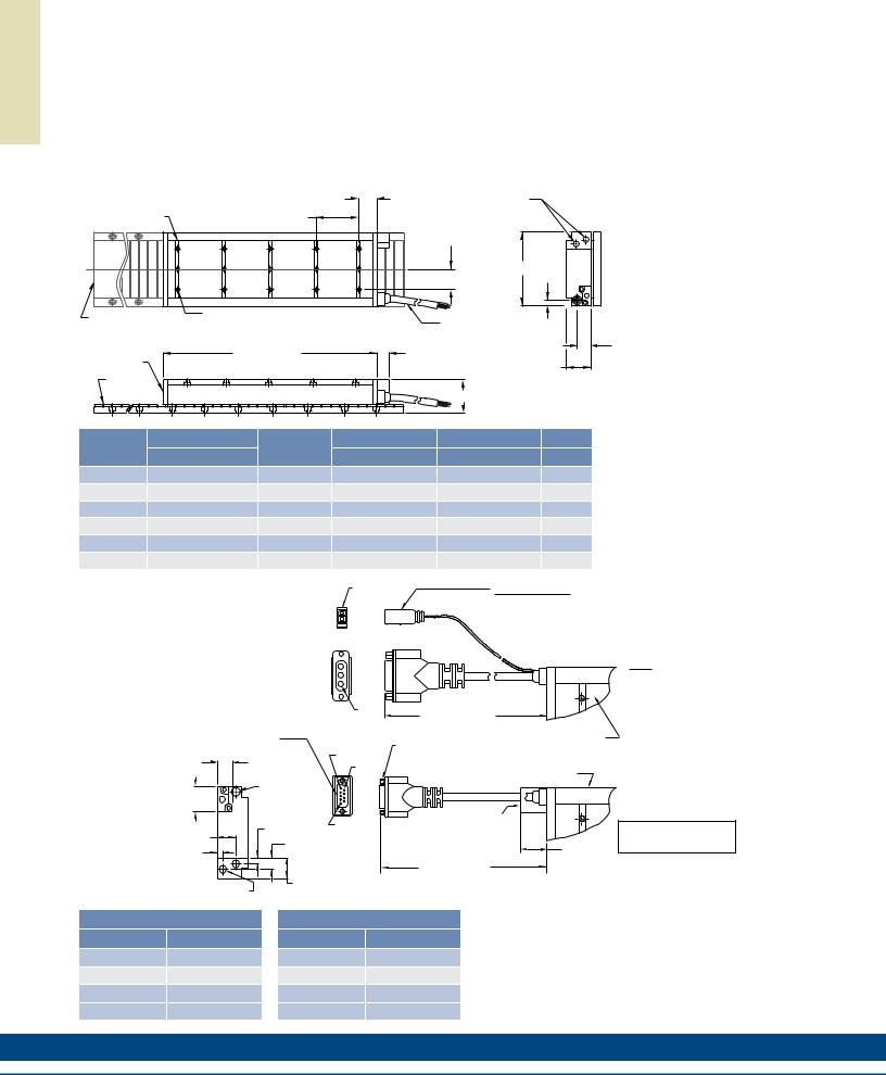
IC11 Outline Drawings
Ironcore Water-Cooled Motors Series |
25.1 |
OPTIONAL COOLING |
|
|
|
|
|
||
MOUNTING BAR |
75.0 |
(.988) |
(SEE OPTIONS BELOW) |
|
(2.953) |
|
|
|
|
3 PER MOTOR |
2 PL. |
|
"C" DISTANCE BETWEEN |
|
|
|
|
MOUNTING HOLES |
|
|
|
|
(SEE PAGE 69) |
|
|
|
|
"A" |
11.9 |
|
|
|
(.469) |
|
|
|
|
|
|
OPTIONAL STAINLESS |
M5 X 0.8 X 8 DP. |
FOR MOTOR CABLE |
|
|
"N" NUMBER OF HOLES |
|
|||
STEEL MAGNET COVER |
AND HALL EFFECT MTG. |
|
||
PER MOUNTING BAR |
|
|||
|
SEE OPTIONS BELOW |
|
||
|
|
|
|
|
COIL ASSEMBLY |
|
|
43.3 REF |
|
|
|
|
|
|
|
200. ±2.6 |
19.1 |
|
|
|
(7.882 |
±.024) |
|
|
|
|
|
(.750) |
|
MAGNET |
|
|
|
|
WAY REF |
|
|
"B" |
|
|
|
|
|
|
Resultant airgap = 0.9mm (.036) nominal (0.5mm (.020”) minimum) when components are set up to dimension “B” in table below. (Please refer to installation manual for more detail)
22.7
(.894)
Motor Coil |
Coil Width |
Cooled |
Dim "B" |
Dim "B" |
# Holes |
|
Type |
"A" |
without Cover |
w/ Magnet Cover |
"N" |
||
|
||||||
IC11-030 |
65.0 (2.559) ± 1.0 (.04) |
ICXX-030 |
58.3±0.1 (2.295±.004) |
58.6±0.1 (2.307±.004) |
2 |
|
IC11-050 |
85.0 (3.346) ± 1.0 (.04) |
ICXX-050 |
58.3±0.1 (2.295±.004) |
58.6±0.1 (2.307±.004) |
2 |
|
IC11-075 |
110.0 (4.331) ± 1.0 (.04) |
ICXX-075 |
58.3±0.1 (2.295±.004) |
58.6±0.1 (2.307±.004) |
3 |
|
IC11-100 |
135.0 (5.315) ± 1.0 (.04) |
ICXX-100 |
58.3±0.1 (2.295±.004) |
58.6±0.1 (2.307±.004) |
3 |
|
IC11-150 |
185.0 (7.283) ± 1.0 (.06) |
ICXX-150 |
60.3±0.1 (2.374±.004) |
60.6±0.1 (2.386±.004) |
5 |
|
IC11-200 |
235.0 (9.252) ± 1.0 (.06) |
ICXX-200 |
60.3±0.1 (2.374±.004) |
60.6±0.1 (2.386±.004) |
6 |
Termination and Hall Effect Options |
PIN1 |
|
THERMAL PROTECTION CONNECTOR: |
|
|
|
|
|
2 PIN - MALE CONNECTOR |
|
|
1 |
|
FREE HANGING RECEPTACLE |
|
THERMAL |
|
MOLEX P/N 43025-0200 |
|
|
2 |
|
||
|
|
2 FEMALE TERMINALS |
||
|
|
|
|
|
|
|
|
|
MOLEX P/N 43030-0010 |
|
MOTOR |
|
|
|
LL EFFECT CONNECTOR OPTION: |
|
|
|
|
OSITRONIC P/N: MD9M2000Z |
|
|
|
|
PIN, MALE |
|
PIN1 |
STANDARD LENGTH, |
|
ATING CONNECTOR REFERENCE: |
|
|
||
|
SEE TABLE |
|
||
OSITRONIC P/N: MD9F2000X |
|
|
|
|
|
|
|
|
|
EE WIRE TABLE, PAGE 70 |
|
|
#4-40 JACKNUT (2) |
COIL ASSEMBLY REF |
|
|
|
|
|
|
|
PIN 5 |
(REMOVABLE FOR BULKHEAD MOUNTING) |
|
14.6 |
|
|
|
|
|
PIN 9 |
|
|
|
(.575) |
|
|
COIL ASSEMBLY REF |
|
|
|
|
||
|
|
|
|
|
MOTOR CABLE |
|
|
|
|
|
HALL |
|
|
|
|
EFFECT |
|
|
|
|
|
PIN 1 |
HALL EFFECT ASSEMBLY |
|
8.4 (.331) |
|
|
||
|
|
|
||
) |
16.2 (.637) |
|
|
|
|
|
|
26.8 |
|
|
|
|
|
|
|
|
|
|
(1.055) |
|
|
|
STANDARD LENGTH, |
MAX. |
|
|
|
|
|
|
32.0 (1.260) |
|
SEE TABLE |
|
G OPTION: |
|
|
|
|
|
|
|
|
|
NPT (FEMALE) 2 PL. |
|
|
|
|
Connector Option
Connector |
Length |
|
P1 |
400 (16) |
|
P2 |
200 (8) |
|
P3 |
100 |
(4) |
P4 |
1200 |
(48) |
Flying Lead Option
Leads |
Length |
|
C1 |
400 (16) |
|
C2 |
200 (8) |
|
C3 |
100 |
(4) |
C4 |
1200 |
(48) |
Note:
Cables exiting motor and hall effects are not dynamic flex cables. For high life flex
extension cables, see page 72
Notes:
1.Dimensions in mm (inches)
2.Tolerances unless otherwise specified: no decimal place ±0.8 (0.3)
X decimal place ±0.1 (.004)
XX decimal place ±0.05 (0.002)
MATING CONNECTOR REFERENCE:
MOLEX "MICRO-FIT 3.0"
PLUG: 43020-0201
MALE TERMINALS: 43031-0010
SEE WIRE TABLE, PAGE 70
MOTOR CONNECTOR:
POSITRONIC P/N: CBD3W3M0000Z 3 PIN, MALE SHELL, SIZE 2
MALE CONTACTS:
POSITRONIC P/N: MS40--D 3 REMOVABLE MALE CONTACTS, SIZE 8
MATING CONNECTOR REFERENCE:
POSITRONIC P/N: CBD3W3F0000X 3 FEMALE SOCKETS, SOLDER TYPE, SIZE 8, POSITRONIC P/N: FS40--D
SEE WIRE TABLE, PAGE 70
HALL EFFECT MASS
W/P* CONNECTOR: .07 KG (.15 LB) MAX
W/C* CABLE: .03 KG (.07 LB) MAX
w w w. k o l l m o r g e n . c o m |
55 |
S G N I W A R D E N I L T U O S E I R E S 1 1 C I D E L O O C
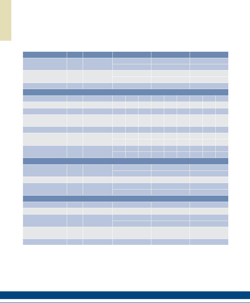
A T A D E C N A M R O F R E P 2 2 C I
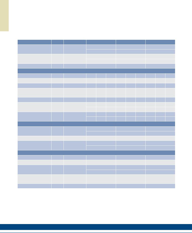
IC22 Performance Data
Ironcore Water-Cooled Motors Series
Rated Perfomance |
Symbol |
Units |
|
IC22-030 |
|
|
IC22-050 |
|
|
IC22-075 |
|
|
Peak Force |
Fp |
N |
|
630 |
|
|
1051 |
|
|
1576 |
|
|
lbf |
|
142 |
|
|
236 |
|
|
354 |
|
|||
|
|
|
|
|
|
|
|
|||||
Continuous Force @ Tmax (1) |
Fc |
N |
|
519 |
|
|
864 |
|
|
1284 |
|
|
lbf |
|
117 |
|
|
194 |
|
|
287 |
|
|||
|
|
|
|
|
|
|
|
|||||
Motor Constant @ 25°C |
Km |
N/√W |
|
28.3 |
|
|
40.5 |
|
|
52.2 |
|
|
|
|
Electrical Specifications (2) |
|
|
|
|
|
|
||||
|
|
Winding Code |
A1 |
A2 |
A6 |
A1 |
A2 |
A6 |
A1 |
A2 |
A6 |
|
Peak Current |
lp |
Arms |
13.8 |
27.6 |
47.8 |
13.8 |
27.6 |
47.8 |
13.8 |
27.6 |
47.8 |
|
Continuous Current @Tmax |
lc |
Arms |
9.9 |
19.8 |
34.3 |
9.9 |
19.8 |
34.3 |
9.8 |
19.6 |
34.0 |
|
Elextrical Resistance |
Rm |
Ohms L-L |
3.1 |
0.78 |
0.26 |
4.2 |
1.1 |
0.35 |
5.7 |
1.4 |
0.48 |
|
@ 25°C±10% |
||||||||||||
|
|
|
|
|
|
|
|
|
|
|
||
Electrical Inductance ±20% |
L |
mH L-L |
20.6 |
5.2 |
1.7 |
33.0 |
8.3 |
2.8 |
48.6 |
12.2 |
4.1 |
|
Back EMF Constant |
Ke |
Vpeak/m/s L-L |
49.7 |
24.9 |
14.4 |
82.9 |
41.4 |
23.9 |
124 |
62.2 |
35.9 |
|
@ 25°C±10% |
Vpeak/in/sec L-L |
1.26 |
0.63 |
0.36 |
2.11 |
1.05 |
0.61 |
3.16 |
1.58 |
0.91 |
||
|
||||||||||||
Force Constant |
Kf |
N/Arms |
60.9 |
30.5 |
17.6 |
102 |
50.8 |
29.3 |
152 |
76.2 |
44.0 |
|
@ 25°C±10% |
lbf/Arms |
13.7 |
6.8 |
4.0 |
22.8 |
11.4 |
6.6 |
34.2 |
17.1 |
9.9 |
||
|
||||||||||||
|
|
Mechanical Specifications |
|
|
|
|
|
|
||||
Coil Assembly Mass ±15% |
Mc |
kg |
|
4.8 |
|
|
6.9 |
|
|
9.6 |
|
|
lbs |
|
10.6 |
|
|
15.2 |
|
|
21.2 |
|
|||
|
|
|
|
|
|
|
|
|||||
Magnetic Way Type |
|
|
|
MC030 |
|
|
MC050 |
|
|
MC075 |
|
|
Magnetic Way Mass ±15% |
Mw |
kg/m |
|
5.4 |
|
|
7.5 |
|
|
10.1 |
|
|
lb/in |
|
0.30 |
|
|
0.42 |
|
|
0.56 |
|
|||
|
|
|
|
|
|
|
|
|||||
|
|
Figures of Merit and Additional Data |
|
|
|
|
|
|||||
Electrical Time Constant |
Te |
ms |
|
6.6 |
|
|
7.9 |
|
|
8.5 |
|
|
Max.Theoretical Acceleration (3) |
Amax |
g’s |
|
15.9 |
|
|
18.5 |
|
|
19.9 |
|
|
Magnetic Attraction |
Fa |
kN |
|
2.9 |
|
|
4.9 |
|
|
7.3 |
|
|
lbf |
|
654 |
|
|
1090 |
|
|
1637 |
|
|||
|
|
|
|
|
|
|
|
|||||
Thermal Resistance (4) |
Rth |
°C/Watt |
|
0.16 |
|
|
0.12 |
|
|
0.091 |
|
|
(coils to external structure) |
|
|
|
|
|
|
||||||
|
|
|
|
|
|
|
|
|
|
|
||
Max. Allowable Coil Temp. (4) |
Tmax |
°C |
|
130 |
|
|
130 |
|
|
130 |
|
|
Notes:
1.The motor continuous rated force is measured with the motor coils achieving the motor maximum allowable temperature Tmax.
2.Alternate windings can be made available. Please consult the Kollmorgen Customer Support for design options.
3.Maximum theoretical acceleration is based on the motors peak force and the motor mass alone. Limitations due to such factors as the additional mass of the load, the bearing type and design, the shock rating of the feedback, the peak current available from the amplifier etc. must be considered to determine the achievable acceleration in each application.
4.Please see our application sizing pages in the back of this guide for more details on sizing and thermal considerations.
56 |
K O L L M O R G E N |
Rated Perfomance |
Symbol |
Units |
|
IC22-100 |
|
|
IC22-150 |
|
|
IC22-200 |
|
|
Peak Force |
Fp |
N |
|
2106 |
|
|
3152 |
|
|
4204 |
|
|
lbf |
|
473 |
|
|
709 |
|
|
945 |
|
|||
|
|
|
|
|
|
|
|
|||||
Continuous Force @ Tmax (1) |
Fc |
N |
|
1715 |
|
|
2566 |
|
|
3458 |
|
|
lbf |
|
386 |
|
|
577 |
|
|
777 |
|
|||
|
|
|
|
|
|
|
|
|||||
Motor Constant @ 25°C |
Km |
N/√W |
|
62.5 |
|
|
79.3 |
|
|
93.3 |
|
|
|
|
Electrical Specifications (2) |
|
|
|
|
|
|
||||
|
|
Winding Code |
A1 |
A2 |
A6 |
A1 |
A2 |
A6 |
A1 |
A2 |
A6 |
|
Peak Current |
lp |
Arms |
13.8 |
27.6 |
47.8 |
13.8 |
27.6 |
47.8 |
13.8 |
27.6 |
47.8 |
|
Continuous Current @Tmax |
lc |
Arms |
9.8 |
19.6 |
34.0 |
9.8 |
19.7 |
34.1 |
9.9 |
19.8 |
34.3 |
|
Elextrical Resistance |
Rm |
Ohms L-L |
7.1 |
1.8 |
0.59 |
9.9 |
2.5 |
0.83 |
12.7 |
3.2 |
1.1 |
|
@ 25°C±10% |
||||||||||||
|
|
|
|
|
|
|
|
|
|
|
||
Electrical Inductance ±20% |
L |
mH L-L |
64.1 |
16.0 |
5.3 |
95.4 |
23.9 |
8.0 |
127 |
31.6 |
10.5 |
|
Back EMF Constant |
Ke |
Vpeak/m/s L-L |
166 |
83.1 |
48.0 |
249 |
124 |
71.8 |
332 |
166 |
95.7 |
|
@ 25°C±10% |
Vpeak/in/sec L-L |
4.22 |
2.11 |
1.22 |
6.32 |
3.16 |
1.82 |
8.42 |
4.21 |
2.43 |
||
|
||||||||||||
Force Constant |
Kf |
N/Arms |
203 |
102 |
58.7 |
305 |
152 |
87.9 |
406 |
203 |
117 |
|
@ 25°C±10% |
lbf/Arms |
45.7 |
22.9 |
13.2 |
68.5 |
34.2 |
19.8 |
91.3 |
45.7 |
26.4 |
||
|
||||||||||||
|
|
Mechanical Specifications |
|
|
|
|
|
|
||||
Coil Assembly Mass ±15% |
Mc |
kg |
|
12.5 |
|
|
18.1 |
|
|
23.7 |
|
|
lbs |
|
27.6 |
|
|
39.9 |
|
|
52.2 |
|
|||
|
|
|
|
|
|
|
|
|||||
Magnetic Way Type |
|
|
|
MC100 |
|
|
MC150 |
|
|
MC200 |
|
|
Magnetic Way Mass ±15% |
Mw |
kg/m |
|
12.7 |
|
|
20.7 |
|
|
26.8 |
|
|
lb/in |
|
0.71 |
|
|
1.16 |
|
|
1.50 |
|
|||
|
|
|
|
|
|
|
|
|||||
|
|
Figures of Merit and Additional Data |
|
|
|
|
|
|||||
Electrical Time Constant |
Te |
ms |
|
9.0 |
|
|
9.6 |
|
|
10.0 |
|
|
Max.Theoretical Acceleration (3) |
Amax |
g’s |
|
20.4 |
|
|
21.1 |
|
|
21.5 |
|
|
Magnetic Attraction |
Fa |
kN |
|
9.8 |
|
|
14.6 |
|
|
19.7 |
|
|
lbf |
|
2205 |
|
|
3271 |
|
|
4433 |
|
|||
|
|
|
|
|
|
|
|
|||||
Thermal Resistance (4) |
Rth |
°C/Watt |
|
0.073 |
|
|
0.052 |
|
|
0.040 |
|
|
(coils to external structure) |
|
|
|
|
|
|
||||||
|
|
|
|
|
|
|
|
|
|
|
||
Max. Allowable Coil Temp. (4) |
Tmax |
°C |
|
130 |
|
|
130 |
|
|
130 |
|
|
Notes:
1.The motor continuous rated force is measured with the motor coils achieving the motor maximum allowable temperature Tmax.
2.Alternate windings can be made available. Please consult the Kollmorgen Customer Support for design options.
3.Maximum theoretical acceleration is based on the motors peak force and the motor mass alone. Limitations due to such factors as the additional mass of the load, the bearing type and design, the shock rating of the feedback, the peak current available from the amplifier etc. must be considered to determine the achievable acceleration in each application.
4.Please see our application sizing pages in the back of this guide for more details on sizing and thermal considerations.
A T A D E C N A M R O F R E P 2 2 C I
w w w. k o l l m o r g e n . c o m |
57 |
|
|
|
|
S G N I W A R D E N I L T U O 2 2 C I
IC22 Outline Drawings
Ironcore Water-Cooled Motors Series |
|
|
|
|
|
||
|
|
|
38.1 |
OPTIONAL COOLING |
|
|
|
MOUNTING BAR |
|
75.0 |
(1.500) |
(SEE OPTIONS BELOW) |
|
|
|
|
(2.953) |
|
|
|
|
|
|
5 PER MOTOR |
|
4 PL. |
|
"C" DISTANCE BETWEEN |
|
|
|
|
|
|
|
MOUNTING HOLES |
|
|
|
|
|
|
|
(SEE PAGE 69) |
|
|
|
|
|
|
|
|
"A" |
11.9 |
|
|
|
|
|
|
(.469) |
|
|
|
|
|
|
|
|
|
|
OPTIONAL STAINLESS |
M5 X 0.8 X 8 DP. |
|
|
|
|
|
|
"N" NUMBER OF HOLES |
|
FOR MOTOR CABLE |
|
|
|
||
STEEL MAGNET COVER |
|
|
|
|
|||
PER MOUNTING BAR |
|
AND HALL EFFECT MTG. |
|
|
|||
|
|
|
|
||||
|
376. ±2.6 |
|
SEE OPTIONS BELOW |
|
|
22.7 |
|
|
|
19.1 |
|
|
|||
COIL ASSEMBLY |
(14.811 |
±.024) |
|
|
|
(.894) |
|
|
|
|
(.750) |
43.3 REF |
|
||
|
|
|
|
|
|
||
MAGNET |
|
|
|
|
|
|
|
WAY REF |
|
|
|
"B" |
|
|
|
|
|
|
|
|
|
|
|
Resultant airgap = 0.9mm (.036) nominal (0.5mm (.020”) minimum) when components are set up to dimension “B” in table below. (Please refer to installation manual for more detail)
Motor Coil |
Coil Width |
Cooled |
Dim "B" |
Dim "B" |
# Holes |
|
Type |
"A" |
without Cover |
w/ Magnet Cover |
"N" |
||
|
||||||
IC22-030 |
65.0 (2.559) ± 1.0 (.04) |
ICXX-030 |
58.3±0.1 (2.295±.004) |
58.6±0.1 (2.307±.004) |
2 |
|
IC22-050 |
85.0 (3.346) ± 1.0 (.04) |
ICXX-050 |
58.3±0.1 (2.295±.004) |
58.6±0.1 (2.307±.004) |
2 |
|
IC22-075 |
110.0 (4.331) ± 1.0 (.04) |
ICXX-075 |
58.3±0.1 (2.295±.004) |
58.6±0.1 (2.307±.004) |
3 |
|
IC22-100 |
135.0 (5.315) ± 1.0 (.04) |
ICXX-100 |
58.3±0.1 (2.295±.004) |
58.6±0.1 (2.307±.004) |
3 |
|
IC22-150 |
185.0 (7.283) ± 1.0 (.06) |
ICXX-150 |
60.3±0.1 (2.374±.004) |
60.6±0.1 (2.386±.004) |
5 |
|
IC22-200 |
235.0 (9.252) ± 1.0 (.06) |
ICXX-200 |
60.3±0.1 (2.374±.004) |
60.6±0.1 (2.386±.004) |
6 |
Notes:
1.Dimensions in mm (inches)
2.Tolerances unless otherwise specified: no decimal place ±0.8 (0.3)
X decimal place ±0.1 (.004)
XX decimal place ±0.05 (0.002)
Termination and Hall Effect Options |
|
PIN1 |
|
2 PIN - MALE CONNECTOR |
||
|
|
|
|
|
THERMAL PROTECTION CONNECTOR: |
|
|
|
|
|
1 |
|
FREE HANGING RECEPTACLE |
|
|
|
THERMAL |
|
MOLEX P/N 43025-0200 |
|
|
|
|
2 |
|
||
|
|
|
|
2 FEMALE TERMINALS |
||
|
|
|
|
|
|
|
|
|
|
|
|
|
MOLEX P/N 43030-0010 |
|
|
|
MOTOR |
|
|
|
HALL EFFECT CONNECTOR OPTION: |
|
|
|
|||
POSITRONIC P/N: MD9M2000Z |
|
|
|
|
|
|
9 PIN, MALE |
|
|
|
PIN1 |
STANDARD LENGTH, |
|
MATING CONNECTOR REFERENCE: |
|
|
|
|||
|
|
SEE TABLE |
|
|||
POSITRONIC P/N: MD9F2000X |
|
|
|
|
||
|
|
|
|
|
||
SEE WIRE TABLE, PAGE 70 |
|
|
|
|
#4-40 JACKNUT (2) |
COIL ASSEMBLY REF |
|
|
|
|
|
|
|
|
|
|
|
PIN 5 |
(REMOVABLE FOR BULKHEAD MOUNTING) |
|
14.6 |
|
|
|
|
|
|
|
|
|
PIN 9 |
|
|
|
(.575) |
|
|
|
|
COIL ASSEMBLY REF |
|
|
|
|
|
|
||
|
|
|
|
|
|
|
MOTOR CABLE |
|
|
|
|||
31.7 |
|
|
HALL |
|
|
|
(1.25) |
|
|
EFFECT |
|
|
|
|
|
|
|
PIN 1 |
HALL EFFECT ASSEMBLY |
|
26.4 |
8.4 (.331) |
|
|
|
||
|
|
|
|
|||
|
|
|
|
|
|
|
(1.038) |
|
16.2 (.637) |
|
|
|
|
|
|
|
|
26.8 |
||
7.8 |
|
|
|
|
|
|
|
|
|
|
|
(1.055) |
|
(.308) |
|
|
|
|
|
|
|
|
|
|
STANDARD LENGTH, |
MAX. |
|
|
|
|
|
|
||
|
|
|
|
|
|
|
|
|
|
32.0 (1.260) |
|
SEE TABLE |
|
COOLING OPTION: |
|
|
|
|
|
|
|
|
|
|
|
|
|
1/8-27 NPT (FEMALE) 2 PL. |
|
|
|
|
|
|
MATING CONNECTOR REFERENCE:
MOLEX "MICRO-FIT 3.0" PLUG: 43020-0201
MALE TERMINALS: 43031-0010 SEE WIRE TABLE, PAGE 70
MOTOR CONNECTOR:
POSITRONIC P/N: CBD3W3M0000Z 3 PIN, MALE SHELL, SIZE 2
MALE CONTACTS:
POSITRONIC P/N: MS40--D 3 REMOVABLE MALE CONTACTS, SIZE 8
MATING CONNECTOR REFERENCE:
POSITRONIC P/N: CBD3W3F0000X 3 FEMALE SOCKETS, SOLDER TYPE, SIZE 8, POSITRONIC P/N: FS40--D
SEE WIRE TABLE, PAGE 70
HALL EFFECT MASS
W/P* CONNECTOR: .07 KG (.15 LB) MAX W/C* CABLE: .03 KG (.07 LB) MAX
Connector Option
Connector |
Length |
|
P1 |
400 (16) |
|
P2 |
200 (8) |
|
P3 |
100 |
(4) |
P4 |
1200 |
(48) |
58
Flying Lead Option
Leads |
Length |
|
C1 |
400 (16) |
|
C2 |
200 (8) |
|
C3 |
100 |
(4) |
C4 |
1200 |
(48) |
Note:
Cables exiting motor and hall effects are not dynamic flex cables. For high life flex
extension cables, see page 72
K O L L M O R G E N

Notes
S G N I W A R D E N I L T U O 2 2 C I
w w w. k o l l m o r g e n . c o m |
59 |
|
|
|
|
A T A D E C N A M R O F R E P 3 3 C I
IC33 Performance Data
Ironcore Water-Cooled Motors Series
Rated Perfomance |
Symbol |
Units |
|
IC33-030 |
|
|
IC33-050 |
|
|
IC33-075 |
|
|
Peak Force |
Fp |
N |
|
945 |
|
|
1575 |
|
|
2365 |
|
|
lbf |
|
212 |
|
|
354 |
|
|
532 |
|
|||
|
|
|
|
|
|
|
|
|||||
Continuous Force @ Tmax (1) |
Fc |
N |
|
769 |
|
|
1283 |
|
|
1926 |
|
|
lbf |
|
173 |
|
|
288 |
|
|
433 |
|
|||
|
|
|
|
|
|
|
|
|||||
Motor Constant @ 25°C |
Km |
N/√W |
|
34.5 |
|
|
49.2 |
|
|
64.2 |
|
|
|
|
Electrical Specifications (2) |
|
|
|
|
|
|
||||
|
|
Winding Code |
A1 |
A3 |
A5 |
A1 |
A3 |
A5 |
A1 |
A3 |
A5 |
|
Peak Current |
lp |
Arms |
13.8 |
41.4 |
23.9 |
13.8 |
41.4 |
23.9 |
13.8 |
41.4 |
23.9 |
|
Continuous Current @Tmax |
lc |
Arms |
9.8 |
29.5 |
17.0 |
9.8 |
29.4 |
17.0 |
9.8 |
29.4 |
17.0 |
|
Elextrical Resistance |
Rm |
Ohms L-L |
4.7 |
0.52 |
1.6 |
6.4 |
0.71 |
2.1 |
8.5 |
0.94 |
2.8 |
|
@ 25°C±10% |
||||||||||||
|
|
|
|
|
|
|
|
|
|
|
||
Electrical Inductance ±20% |
L |
mH L-L |
31.0 |
3.4 |
10.3 |
49.5 |
5.5 |
16.5 |
73.1 |
8.1 |
24.4 |
|
Back EMF Constant |
Ke |
Vpeak/m/s L-L |
74.5 |
24.8 |
43.0 |
124 |
41.4 |
71.7 |
187 |
62.2 |
108 |
|
@ 25°C±10% |
Vpeak/in/sec L-L |
1.89 |
0.63 |
1.09 |
3.16 |
1.05 |
1.82 |
4.74 |
1.58 |
2.74 |
||
|
||||||||||||
Force Constant |
Kf |
N/Arms |
91.3 |
30.4 |
52.7 |
152 |
50.7 |
87.9 |
229 |
76.2 |
132 |
|
@ 25°C±10% |
lbf/Arms |
20.5 |
6.8 |
11.9 |
34.2 |
11.4 |
19.8 |
51.4 |
17.1 |
29.7 |
||
|
||||||||||||
|
|
Mechanical Specifications |
|
|
|
|
|
|
||||
Coil Assembly Mass ±15% |
Mc |
kg |
|
7.3 |
|
|
10.4 |
|
|
14.4 |
|
|
lbs |
|
16.1 |
|
|
22.9 |
|
|
31.7 |
|
|||
|
|
|
|
|
|
|
|
|||||
Magnetic Way Type |
|
|
|
MC030 |
|
|
MC050 |
|
|
MC075 |
|
|
Magnetic Way Mass ±15% |
Mw |
kg/m |
|
5.4 |
|
|
7.5 |
|
|
10.1 |
|
|
lb/in |
|
0.30 |
|
|
0.42 |
|
|
0.56 |
|
|||
|
|
|
|
|
|
|
|
|||||
|
|
Figures of Merit and Additional Data |
|
|
|
|
|
|||||
Electrical Time Constant |
Te |
ms |
|
6.6 |
|
|
7.7 |
|
|
8.6 |
|
|
Max.Theoretical Acceleration (3) |
Amax |
g’s |
|
15.7 |
|
|
18.4 |
|
|
19.9 |
|
|
Magnetic Attraction |
Fa |
kN |
|
4.4 |
|
|
7.4 |
|
|
11.0 |
|
|
lbf |
|
991 |
|
|
1652 |
|
|
2480 |
|
|||
|
|
|
|
|
|
|
|
|||||
Thermal Resistance (4) |
Rth |
°C/Watt |
|
0.11 |
|
|
0.081 |
|
|
0.061 |
|
|
(coils to external structure) |
|
|
|
|
|
|
||||||
|
|
|
|
|
|
|
|
|
|
|
||
Max. Allowable Coil Temp. (4) |
Tmax |
°C |
|
130 |
|
|
130 |
|
|
130 |
|
|
Notes:
1.The motor continuous rated force is measured with the motor coils achieving the motor maximum allowable temperature Tmax.
2.Alternate windings can be made available. Please consult the Kollmorgen Customer Support for design options.
3.Maximum theoretical acceleration is based on the motors peak force and the motor mass alone. Limitations due to such factors as the additional mass of the load, the bearing type and design, the shock rating of the feedback, the peak current available from the amplifier etc. must be considered to determine the achievable acceleration in each application.
4.Please see our application sizing pages in the back of this guide for more details on sizing and thermal considerations.
60 |
K O L L M O R G E N |