

Linear Engine / DDL_Selection_Guide_en-EN_revA
.pdfIL12 Outline Drawings |
|
|
|
|
|
|
|||||
Ironless Non-Cooled Motors Series |
|
|
|
|
|
|
|
|
|
||
|
|
|
M5 X 0.8 X 5 DP . 8 PL. |
|
|
Motor Coil |
Coil Width |
Typ. Assy. Width Typ. Assy. Width |
|||
|
|
|
|
|
"A" |
+.7 (0.027) |
"B" ±.6 (.024) |
"T" ±.4 (.016) |
|||
|
|
|
(8.142) |
|
|
|
|
-.3 (0.012) |
|||
|
|
|
206.8 |
|
|
|
|
|
|
|
|
|
|
|
MAX. |
|
|
|
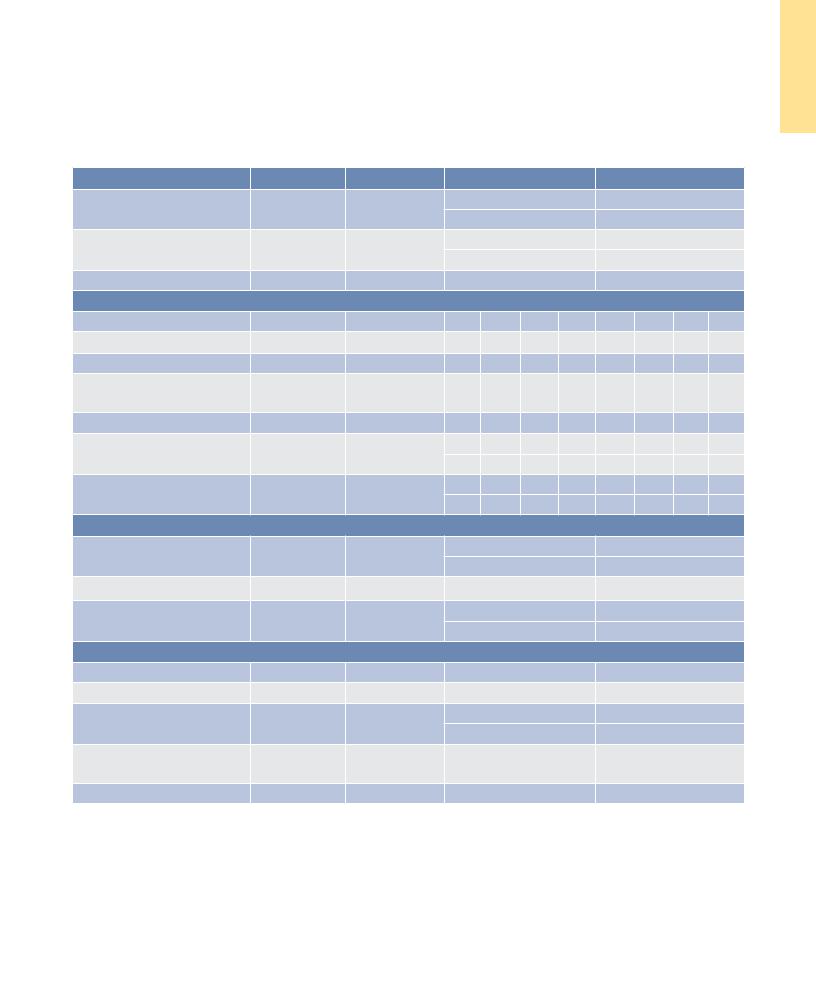
IL12-030 |
57.30 (2.256) |
78.50 (3.091) |
25.40 (1.000) |
|
|
|
|
|
|
|
|
|||||
|
|
|
|
|
|
|
IL12-030 L |
57.30 (2.256) |
67.30 (2.650) |
25.40 (1.000) |
|
4.5 |
|
|
40.0 |
|
16.7 |
|
IL12-050 |
77.30 (3.043) |
98.50 (3.878) |
25.40 (1.000) |
|
|
|
|
|
|
|
|
|
|
|||
(.176) |
|
|
(1.575) |
3.9 |
(.657) |
|
IL12-050 L |
77.30 (3.043) |
87.30 (3.437) |
25.40 (1.000) |
|
FOR MO TO R CABLE |
|
43.4 |
3 PL. |
(.152) |
|
|
IL12-075 |
102.30 (4.028) |
123.50 (4.862) |
30.00 (1.181) |
|
|
|
|
|
||||||||
AND HALL EFFEC T MTG. |
|
(1.709) |
|
|
|
|
|||||
SEE DR AWING BELO W |
|
40.0 |
|
|
|
|
IL12-100 |
127.30 (5.012) |
148.50 (5.846) |
34.00 (1.339) |
|
|
|
|
|
|
|
||||||
|
|
(1.575) |
|
|
|
|
|
|
|
|
|
10.8 |
23.4 |
4 PL. |
|
|
|
Magn et Way |
|
|
Notes: |
|
|
|
|
|
|
|
|
|
|||||
(.427) |
(.921) |
BOTH |
|
|
4.0 |
REF. |
|
|
|
|
|
24.4 |
BOTH |
SIDES |
|
|
(.157) |
|
CO IL ASSEMBLY |
|
1. Dimensions in mm (inches) |
||
(.961) |
SIDES |
|
|
|
|
|
|
1.2 .05 |
|
2. Tolerances unless otherwise specified: |
|
|
|
|
|
|
|
|
|
||||
|
|
|
|
|
|
|
|
(.048 .002) |
|
no decimal place ±0.8 (0.3) |
|
|
|
|
|
|
|
|
|
CLEAR ANCE- |
|
X decimal place ±0.1 (.004) |
|
|
|
|
|
|
"A" |
|
|
SET UP DIM. |
|
||
17.0 |
|
|
|
|
|
|
|
XX decimal place ±0.05 (0.002) |
|||
|
|
|
|
"B" |
|
|
|
||||
|
|
|
|
|
|
|
|
||||
(.669) |
|
|
|
|
|
|
|
|
|
|
|
|
|
|
|
|
|
|
|
|
|
|
|
|
|
|
10.0 |
|
|
|
|
|
|
|
|
|
|
|
|
|
|
|
|
|
CO IL TO MAGNET AIRGAP |
|||
|
|
|
|
|
|
|
|
|
|
|
|
|
|
|
|
|
|
|
|
|||||
|
|
|
|
|
|
|
|
|
|
|
|
|
|
|
|
|
|
|
|
0.74 REF TYP. FO R 030, -050 |
||||
|
|
|
|
|
(.394) |
M5 X 0.8 X 5 DP . |
|
|
|
|
|
|
|
|
|
|
|
|
|
|
||||
4.4 |
|
|
|
|
|
|
|
|
|
|
|
|
|
|
|
|
|
1.12 REF TYP. FO R -075 AND -100 |
||||||
|
|
|
|
|
|
|
|
|
|
|
|
|
|
|
|
|||||||||
|
|
|
|
|
|
|
|
|
|
|
|
|
|
|
|
|
|
|
||||||
(.173) |
|
|
|
|
|
|
10 PL., 5 PER SIDE |
|
|
|
|
|
|
|
|
|
|
|
|
|
|
|
||
|
|
|
|
|
|
|
|
|
|
|
|
"T" |
|
|
|
|
|
|
|
|
|
|
||
|
|
|
|
|
|
|
|
|
|
|
|
|
|
|
|
|
|
|
|
|
|
|
||
|
|
|
|
|
|
|
|
|
|
|
|
|
|
|
|
|
|
|
|
|||||
Termination and Hall Effect Options
|
|
|
PIN 1 |
THERMAL PROTECTION CONNECTOR: |
|
|
|
2 PIN - M ALE C ONNEC TO R |
|
|
|
|
|
|
|
|
1 |
|
FREE HANGING RECEPT ACLE |
|
THERMAL |
|
MOLEX P/N 43025-0200 |
|
12.2 +.3 |
2 |
|
||
|
2 FEM ALE TERMINALS |
|||
|
|
|||
(.480 + .012) |
|
|
|
MOLEX P/N 43030-0010 |
|
|
|
|
|
7.7 + .3 |
|
|
(.303 + .012) |
|
|
MOTOR |
3 |
4.0 +.3 |
2 |
|
(.157 + .012) |
|
1 |
6.8 +.3 |
MOTOR CABLE |
|
|
|
|
|
(.268 + .012) |
|
|
|
PIN 1 |
|
|
|
|
|
|
STANDARD LENGTH, |
|
|
|
OPTIONAL HALL EFFEC |
T |
|
|
||
|
|
SEE TABLE |
|
|||
|
AS SHOWN, MOUNTING HOLES |
|
CO IL ASSEMBLY REF |
|||
|
|
|
||||
|
M3 X 6.3 (.25) MIN. DP |
. 2 PL. |
|
|
||
|
|
|
|
|||
|
|
|
|
|
#4-40 JA CKNUT (2) |
|
HALL EFFEC T CONNECTOR OPTION: |
|
PIN 5 |
|
(REMOV ABLE FOR BULKHEAD MOUNTING) |
|
|
|
|
|
|
|||
|
|
|
|
|
||
POSITR ONIC P/N: MD9M2000Z |
|
|
PIN 9 |
CO IL ASSEMBLY REF |
||
9 PIN, M ALE |
|
|
|
|
||
|
|
|
|
|
|
|
MATING CONNECTOR REFERENCE: |
|
|
|
|
|
|
POSITR ONIC P/N: MD9F2000X |
HALL |
|
|
|
|
|
|
|
EFFEC T |
|
|
|
|
SEE WIRE TABLE, PAGE 70 |
|
|
|
|
|
|
|
|
PIN 1 |
|
|
HALL EFFEC T ASSEMBL Y |
|
|
|
|
|
|
|
|
|
|
|
|
|
|
21.0 |
|
|
|
|
|
STANDARD LENGTH, |
(.827) |
|
|
|
|
|
MAX. |
|
|
|
|
|
|
SEE TABLE |
|
Connector Option
Connector |
Length |
|
P1 |
400 (16) |
|
P2 |
200 (8) |
|
P3 |
100 |
(4) |
P4 |
1200 |
(48) |
Flying Lead Option
Leads |
Length |
|
C1 |
400 (16) |
|
C2 |
200 (8) |
|
C3 |
100 |
(4) |
C4 |
1200 |
(48) |
Note:
Cables exiting motor and hall effects are not dynamic flex cables. For high life flex
extension cables, see page 72
MATING CONNECTOR REFERENCE:
MOLEX " MICR O -FIT 3.0" PL UG: 43020-0201
MALE TERMINALS: 43031-0010
SEE WIRE TABLE, PAGE 70
MOTOR CONNECTOR:
POSITR ONIC P/N: CBD3W3M0000Z 3 PIN M ALE , SHELL SIZE 2
MALE CO NTACTS:
POSITR ONIC P/N: MS40--D 3 REMOV ABLE M ALE CONT ACTS, SIZE 8
MATING CONNECTOR REFERENCE:
POSITR ONIC P/N: CBD3W3F0000X
3 FEM ALE SOCKE TS, SO LDER TYPE, SIZE 8, POSITR ONIC P/N: FS40--D
SEE WIRE TABLE, PAGE 70
HALL EFFEC T MASS
W/P* C ONNEC TO R: .05KG (.11 LB) MAX W/C* C ABLE: .03K G (.06 LB) M AX
w w w. k o l l m o r g e n . c o m |
21 |
S G N I W A R D E N I L T U O 2 1 L I

A T A D E C N A M R O F R E P 8 1 L I
IL18 Performance Data
Ironless Non-Cooled Motors Series
Rated Perfomance |
Symbol |
Units |
|
IL18-030 |
|
|
IL18-050 |
|
|||
Peak Force |
Fp |
N |
|
|
360 |
|
|
600 |
|
|
|
lbf |
|
|
81 |
|
|
135 |
|
|
|||
|
|
|
|
|
|
|
|
||||
Continuous Force @ Tmax (1) |
Fc |
N |
|
|
92.1 |
|
|
131 |
|
|
|
lbf |
|
|
20.7 |
|
|
29.4 |
|
|
|||
|
|
|
|
|
|
|
|
||||
Motor Constant @ 25°C |
Km |
N√W |
|
|
9.7 |
|
|
13.8 |
|
|
|
|
|
Electrical Specifications (2) |
|
|
|
|
|
|
|
||
|
|
Winding Code |
A1 |
A2 |
A3 |
A4 |
A1 |
A2 |
A3 |
A4 |
|
Peak Current |
lp |
Arms |
7.1 |
14.3 |
21.4 |
42.8 |
7.0 |
14.0 |
21.0 |
42.1 |
|
Continuous Current @Tmax |
lc |
Arms |
1.8 |
3.6 |
5.5 |
11.0 |
1.5 |
3.1 |
4.6 |
9.2 |
|
Elextrical Resistance |
Rm |
Ohms L-L |
18.2 |
4.6 |
2.0 |
0.5 |
25.7 |
6.4 |
2.9 |
0.7 |
|
@ 25°C±10% |
|||||||||||
|
|
|
|
|
|
|
|
|
|
||
Electrical Inductance ±20% |
L |
mH L-L |
3.8 |
0.95 |
0.42 |
0.11 |
9.00 |
2.25 |
1.00 |
0.25 |
|
Back EMF Constant |
Ke |
Vpeak/m/s L-L |
41.2 |
20.6 |
13.7 |
6.9 |
69.8 |
34.9 |
23.3 |
11.6 |
|
@ 25°C±10% |
Vpeak/in/sec L-L |
1.05 |
0.52 |
0.35 |
0.17 |
1.77 |
0.89 |
0.59 |
0.30 |
||
|
|||||||||||
Force Constant @ 25°C±10% |
Kf |
N/Arms |
50.5 |
25.3 |
16.8 |
8.4 |
85.5 |
42.8 |
28.5 |
14.3 |
|
lbf/Arms |
11.4 |
5.7 |
3.8 |
1.9 |
19.2 |
9.6 |
6.4 |
3.2 |
|||
|
|
||||||||||
|
|
Mechanical Specifications |
|
|
|
|
|
|
|
||
Coil Assembly Mass ±15% |
Mc |
kg |
|
|
0.57 |
|
|
0.72 |
|
|
|
lbs |
|
|
1.3 |
|
|
1.6 |
|
|
|||
|
|
|
|
|
|
|
|
||||
Magnetic Way Type |
|
|
|
MW |
|
|
MW |
|
|
||
|
|
030 |
|
030L |
|
050 |
|
050L |
|||
|
|
|
|
|
|
||||||
Magnetic Way Mass ±15% |
Mw |
kg/m |
9.4 |
|
7.3 |
|
12.2 |
|
10.2 |
|
|
lb/in |
0.51 |
|
0.40 |
|
0.68 |
|
0.56 |
|
|||
|
|
|
|
|
|
||||||
|
Figures of Merit and Additional Data |
|
|
|
|
|
|
||||
Electrical Time Constant |
Te |
ms |
|
|
0.21 |
|
|
0.35 |
|
|
|
Max.Theoretical Acceleration (3) |
Amax |
g’s |
|
|
64.5 |
|
|
84.9 |
|
|
|
Magnetic Attraction |
Fa |
kN |
|
|
0 |
|
|
0 |
|
|
|
lbf |
|
|
0 |
|
|
0 |
|
|
|||
|
|
|
|
|
|
|
|
||||
Thermal Resistance (4) |
Rth |
°C/Watt |
|
0.536 |
|
|
0.419 |
|
|||
(coils to external structure) |
|
|
|
|
|||||||
|
|
|
|
|
|
|
|
|
|
||
Max. Allowable Coil Temp. (4) |
Tmax |
°C |
|
|
130 |
|
|
130 |
|
|
|
Notes:
1.The motor continuous rated force is measured with the motor coils achieving the motor maximum allowable temperature Tmax.
2.Alternate windings can be made available. Please consult the Kollmorgen Customer Support for design options.
3.Maximum theoretical acceleration is based on the motors peak force and the motor mass alone. Limitations due to such factors as the additional mass of the load, the bearing type and design, the shock rating of the feedback, the peak current available from the amplifier etc. must be considered to determine the achievable acceleration in each application.
4.Please see our application sizing pages in the back of this guide for more details on sizing and thermal considerations.
22 |
K O L L M O R G E N |
Rated Perfomance |
Symbol |
Units |
|
IL18-075 |
|
|
IL18-100 |
|
|||
Peak Force |
Fp |
N |
|
|
900 |
|
|
1200 |
|
|
|
lbf |
|
|
202 |
|
|
270 |
|
|
|||
|
|
|
|
|
|
|
|
||||
Continuous Force @ Tmax (1) |
Fc |
N |
|
|
173 |
|
|
211 |
|
|
|
lbf |
|
|
38.9 |
|
|
47.4 |
|
|
|||
|
|
|
|
|
|
|
|
||||
Motor Constant @ 25°C |
Km |
N√W |
|
|
17.7 |
|
|
21.0 |
|
|
|
|
|
Electrical Specifications (2) |
|
|
|
|
|
|
|
||
|
|
Winding Code |
A1 |
A2 |
A3 |
A4 |
A1 |
A2 |
A3 |
A4 |
|
Peak Current |
lp |
Arms |
7.0 |
14.0 |
21.0 |
42.1 |
7.0 |
14.0 |
21.0 |
42.1 |
|
Continuous Current @Tmax |
lc |
Arms |
1.4 |
2.7 |
4.0 |
8.1 |
1.2 |
2.5 |
3.7 |
7.4 |
|
Elextrical Resistance |
Rm |
Ohms L-L |
35.0 |
8.8 |
3.9 |
1.0 |
44.2 |
11.1 |
4.9 |
1.2 |
|
@ 25°C±10% |
|||||||||||
|
|
|
|
|
|
|
|
|
|
||
Electrical Inductance ±20% |
L |
mH L-L |
15.0 |
3.75 |
1.67 |
0.42 |
21.0 |
5.25 |
2.33 |
0.58 |
|
Back EMF Constant |
Ke |
Vpeak/m/s L-L |
105 |
52.4 |
34.9 |
17.5 |
140 |
69.9 |
46.6 |
23.3 |
|
@ 25°C±10% |
Vpeak/in/sec L-L |
2.66 |
1.33 |
0.89 |
0.44 |
3.55 |
1.77 |
1.18 |
0.59 |
||
|
|||||||||||
Force Constant @ 25°C±10% |
Kf |
N/Arms |
128 |
64.2 |
42.8 |
21.4 |
171 |
85.6 |
57.0 |
28.5 |
|
lbf/Arms |
28.8 |
14.4 |
9.6 |
4.8 |
38.5 |
19.2 |
12.8 |
6.4 |
|||
|
|
||||||||||
|
|
Mechanical Specifications |
|
|
|
|
|
|
|
||
Coil Assembly Mass ±15% |
Mc |
kg |
|
|
0.91 |
|
|
1.10 |
|
|
|
lbs |
|
|
2.0 |
|
|
2.4 |
|
|
|||
|
|
|
|
|
|
|
|
||||
Magnetic Way Type |
|
|
|
MW075 |
|
|
MW100 |
|
|||
Magnetic Way Mass ±15% |
Mw |
kg/m |
|
|
18.9 |
|
|
27.3 |
|
|
|
lb/in |
|
|
1.05 |
|
|
1.51 |
|
|
|||
|
|
|
|
|
|
|
|
||||
|
Figures of Merit and Additional Data |
|
|
|
|
|
|
||||
Electrical Time Constant |
Te |
ms |
|
|
0.43 |
|
|
0.48 |
|
|
|
Max.Theoretical Acceleration (3) |
Amax |
g’s |
|
|
101 |
|
|
111 |
|
|
|
Magnetic Attraction |
Fa |
kN |
|
|
0 |
|
|
0 |
|
|
|
lbf |
|
|
0 |
|
|
0 |
|
|
|||
|
|
|
|
|
|
|
|
||||
Thermal Resistance (4) |
Rth |
°C/Watt |
|
|
0.35 |
|
|
0.29 |
|
|
|
(coils to external structure) |
|
|
|
|
|
|
|||||
|
|
|
|
|
|
|
|
|
|
||
Max. Allowable Coil Temp. (4) |
Tmax |
°C |
|
|
130 |
|
|
130 |
|
|
|
Notes:
1.The motor continuous rated force is measured with the motor coils achieving the motor maximum allowable temperature Tmax.
2.Alternate windings can be made available. Please consult the Kollmorgen Customer Support for design options.
3.Maximum theoretical acceleration is based on the motors peak force and the motor mass alone. Limitations due to such factors as the additional mass of the load, the bearing type and design, the shock rating of the feedback, the peak current available from the amplifier etc. must be considered to determine the achievable acceleration in each application.
4.Please see our application sizing pages in the back of this guide for more details on sizing and thermal considerations.
A T A D E C N A M R O F R E P 8 1 L I
w w w. k o l l m o r g e n . c o m |
23 |
|
|
|
|
S G N I W A R D E N I L T U O 8 1 L I
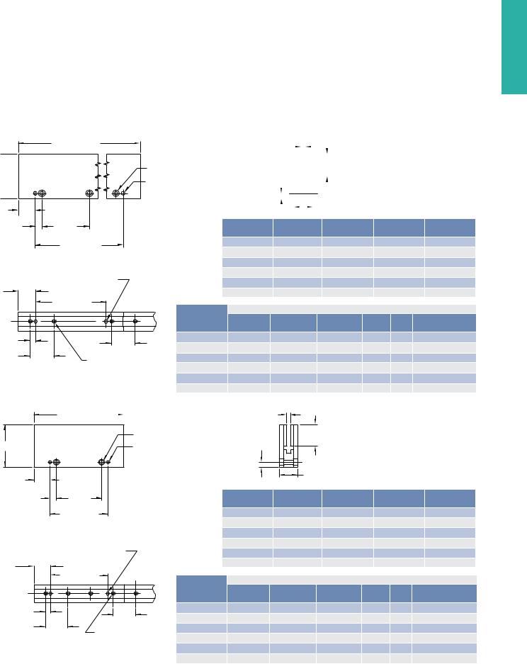
IL18 Outline Drawings |
|
|
|
|
|
||||
Ironless Non-Cooled Motors Series |
|
|
|
|
|
|
|||
|
|
|
|
|
Motor Coil |
Coil Width |
Typ. Assy. Width Typ. Assy. Width |
||
|
|
|
|
|
"A" |
+.7 (0.027) |
"B" ±.6 (.024) |
"T" ±.4 (.016) |
|
|
|
|
302.8 (11.922) MAX. |
|
|
-.3 (0.012) |
|||
|
|
|
16.7 |
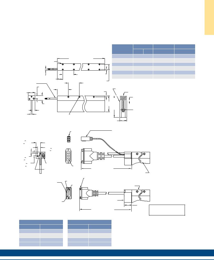
IL18-030 |
57.30 (2.256) |
78.50 (3.091) |
25.40 (1.000) |
||
|
|
|
|
||||||
|
|
|
|
(.657) |
IL18-030 L |
57.30 (2.256) |
67.30 (2.650) |
25.40 (1.000) |
|
|
|
|
|
|
|||||
|
|
|
|
|
IL18-050 |
77.30 (3.043) |
98.50 (3.878) |
25.40 (1.000) |
|
4.5 |
|
|
40.0 |
|
IL18-050 L |
77.30 (3.043) |
87.30 (3.437) |
25.40 (1.000) |
|
(.176) |
|
|
(1.575) |
3.9 |
|||||
|
|
51.4 |
5 PL. |
IL18-075 |
102.30 (4.028) |
123.50 (4.862) |
30.00 (1.181) |
||
|
|
(.152) |
|||||||
FOR MOTOR CABLE |
|
|
|||||||
|
(2.023) |
|
|
IL18-100 |
127.30 (5.012) |
148.50 (5.846) |
34.00 (1.339) |
||
AND HALL EFFECT MTG. |
|
|
40.0 |
M5 X 0.8 X |
|||||
SEE DRAWING BELOW |
|
|
|
|
|
|
|
||
|
|
|
(1.575) |
5 DP. 12 PL. |
|
|
|
|
|
10.8 |
31.4 |
|
6 PL. |
MAGNET WAY |
|
|
|
Notes: |
|
|
|
|
|
|
|
||||
(.427) |
(1.236) |
|
BOTH |
REF. |
|
|
|
1. Dimensions in mm (inches) |
|
24.4 |
BOTH |
|
SIDES |
4.0 |
COIL ASSEMBLY |
|
|
2. Tolerances unless otherwise specified: |
|
SIDES |
|
|
(.157) |
|
|
||||
(.961) |
|
|
|
|
no decimal place ±0.8 (0.3) |
||||
|
|
|
|
1.2 .05 |
|
|
|||
|
|
|
|
|
|
|
X decimal place ±0.1 (.004) |
||
|
|
|
|
|
(.048 .002) |
|
|
XX decimal place ±0.05 (0.002) |
|
|
17.0 |
|
|
|
CLEARANCE- |
|
|
||
|
|
|
"A" |
SET UP DIM. |
|
|
|
|
|
|
(.669) |
|
|
"B" |
|
|
|
|
|
|
10.0 |
|
|
|
COIL TO MAGNET AIRGAP |
|
|
|
|
4.4 |
(.394) |
|
M5 X 0.8 X 5 DP. |
|
0.74 REF TYP. FOR 030, -050 |
|
|
|
|
|
|
|
1.12 REF TYP. FOR -075 AND -100 |
|
|
|
|||
(.173) |
|
|
14 PL., 7 PER SIDE |
|
|
|
|
|
|
|
|
|
|
"T" |
|
|
|
|
|
Termination and Hall Effect Options
|
|
|
PIN 1 |
THERMAL PROTECTION CONNECTOR: |
|
|
|
2 PIN - M ALE C ONNEC TO R |
|
|
|
|
|
|
|
|
1 |
|
FREE HANGING RECEPT ACLE |
|
THERMAL |
|
MOLEX P/N 43025-0200 |
|
12.2 +.3 |
2 |
|
||
|
2 FEM ALE TERMINALS |
|||
|
|
|||
(.480 + .012) |
|
|
|
MOLEX P/N 43030-0010 |
|
|
|
|
|
7.7 + .3 |
|
|
(.303 + .012) |
|
|
MOTOR |
3 |
4.0 +.3 |
2 |
|
(.157 + .012) |
|
1 |
6.8 +.3 |
MOTOR CABLE |
|
|
|
|
|
(.268 + .012) |
|
|
|
PIN 1 |
|
|
|
|
|
|
STANDARD LENGTH, |
|
|
|
OPTIONAL HALL EFFEC |
T |
|
|
||
|
|
SEE TABLE |
|
|||
|
AS SHOWN, MOUNTING HOLES |
|
CO IL ASSEMBLY REF |
|||
|
|
|
||||
|
M3 X 6.3 (.25) MIN. DP |
. 2 PL. |
|
|
||
|
|
|
|
|||
|
|
|
|
|
#4-40 JA CKNUT (2) |
|
HALL EFFEC T CONNECTOR OPTION: |
|
PIN 5 |
|
(REMOV ABLE FOR BULKHEAD MOUNTING) |
|
|
|
|
|
|
|||
|
|
|
|
|
||
POSITR ONIC P/N: MD9M2000Z |
|
|
PIN 9 |
CO IL ASSEMBLY REF |
||
9 PIN, M ALE |
|
|
|
|
||
|
|
|
|
|
|
|
MATING CONNECTOR REFERENCE: |
|
|
|
|
|
|
POSITR ONIC P/N: MD9F2000X |
HALL |
|
|
|
|
|
|
|
EFFEC T |
|
|
|
|
SEE WIRE TABLE, PAGE 70 |
|
|
|
|
|
|
|
|
PIN 1 |
|
|
HALL EFFEC T ASSEMBL Y |
|
|
|
|
|
|
|
|
|
|
|
|
|
|
21.0 |
|
|
|
|
|
STANDARD LENGTH, |
(.827) |
|
|
|
|
|
MAX. |
|
|
|
|
|
|
SEE TABLE |
|
Connector Option
Connector |
Length |
|
P1 |
400 (16) |
|
P2 |
200 (8) |
|
P3 |
100 |
(4) |
P4 |
1200 |
(48) |
Flying Lead Option
Leads |
Length |
|
C1 |
400 (16) |
|
C2 |
200 (8) |
|
C3 |
100 |
(4) |
C4 |
1200 |
(48) |
Note:
Cables exiting motor and hall effects are not dynamic flex cables. For high life flex
extension cables, see page 72
MATING CONNECTOR REFERENCE:
MOLEX " MICR O -FIT 3.0" PL UG: 43020-0201
MALE TERMINALS: 43031-0010
SEE WIRE TABLE, PAGE 70
MOTOR CONNECTOR:
POSITR ONIC P/N: CBD3W3M0000Z 3 PIN M ALE , SHELL SIZE 2
MALE CO NTACTS:
POSITR ONIC P/N: MS40--D 3 REMOV ABLE M ALE CONT ACTS, SIZE 8
MATING CONNECTOR REFERENCE:
POSITR ONIC P/N: CBD3W3F0000X
3 FEM ALE SOCKE TS, SO LDER TYPE, SIZE 8, POSITR ONIC P/N: FS40--D
SEE WIRE TABLE, PAGE 70
HALL EFFEC T MASS
W/P* C ONNEC TO R: .05KG (.11 LB) MAX W/C* C ABLE: .03K G (.06 LB) M AX
24 |
K O L L M O R G E N |

Notes
S G N I W A R D E N I L T U O 8 1 L I
w w w. k o l l m o r g e n . c o m |
25 |
|
|
|
|
A T A D E C N A M R O F R E P 4 2 L I
IL24PerformanceData
Ironless Non-Cooled Motors Series
Rated Perfomance |
Symbol |
Units |
IL24-030 |
IL24-050 |
|
IL24-075 |
|
|
IL24-100 |
|
|||||||
Peak Force |
Fp |
N |
|
480 |
|
|
800 |
|
|
1200 |
|
|
1600 |
|
|||
lbf |
|
108 |
|
|
180 |
|
|
270 |
|
|
360 |
|
|||||
|
|
|
|
|
|
|
|
|
|
||||||||
Continuous Force @ Tmax (1) |
Fc |
N |
|
109 |
|
|
155 |
|
|
211 |
|
|
262 |
|
|||
lbf |
|
24.5 |
|
|
34.8 |
|
|
47.4 |
|
|
58.9 |
|
|||||
|
|
|
|
|
|
|
|
|
|
||||||||
Motor Constant @ 25°C |
Km |
N√W |
|
11.2 |
|
|
15.9 |
|
|
20.6 |
|
|
24.4 |
|
|||
|
|
Electrical Specifications (2) |
|
|
|
|
|
|
|
|
|
||||||
|
|
Winding Code |
A1 |
A2 |
A3 |
A1 |
A2 |
A3 |
A1 |
A2 |
A3 |
A4 |
A1 |
A2 |
A3 |
A4 |
|
Peak Current |
lp |
Arms |
7.1 |
14.2 |
28.5 |
7.0 |
14.0 |
28.1 |
7.0 |
14.0 |
28.0 |
56.1 |
7.0 |
14.0 |
28.1 |
56.1 |
|
Continuous Current @Tmax |
lc |
Arms |
1.6 |
3.2 |
6.4 |
1.4 |
2.7 |
5.4 |
1.2 |
2.5 |
4.9 |
9.9 |
1.2 |
2.3 |
4.6 |
9.2 |
|
Elextrical Resistance |
Rm |
Ohms L-L |
24.3 |
6.1 |
1.5 |
34.3 |
8.6 |
2.1 |
46.6 |
11.7 |
2.9 |
0.73 |
58.9 |
14.7 |
3.7 |
0.92 |
|
@ 25°C±10% |
|||||||||||||||||
|
|
|
|
|
|
|
|
|
|
|
|
|
|
|
|
||
Electrical Inductance ±20% |
L |
mH L-L |
5.1 |
1.28 |
0.32 |
12.0 |
3.00 |
0.75 |
20.0 |
5.0 |
1.25 |
0.31 |
28.0 |
7.00 |
1.75 |
0.44 |
|
Back EMF Constant |
Ke |
Vpeak/m/s L-L |
55.0 |
27.5 |
13.8 |
93.1 |
46.5 |
23.3 |
140. |
69.9 |
34.9 |
17.5 |
186 |
93.1 |
46.6 |
23.3 |
|
@ 25°C±10% |
Vpeak/in/sec L-L |
1.40 |
0.70 |
0.35 |
2.36 |
1.18 |
0.59 |
3.55 |
1.77 |
0.89 |
0.44 |
4.73 |
2.37 |
1.18 |
0.59 |
||
|
|||||||||||||||||
Force Constant |
Kf |
N/Arms |
67.4 |
33.7 |
16.9 |
114 |
57.0 |
28.5 |
171 |
85.6 |
42.8 |
21.4 |
228 |
114 |
57.0 |
28.5 |
|
@ 25°C±10% |
lbf/Arms |
15.2 |
7.6 |
3.8 |
25.6 |
12.8 |
6.4 |
38.5 |
19.2 |
9.6 |
4.8 |
51.3 |
25.6 |
12.8 |
6.4 |
||
|
|||||||||||||||||
|
|
Mechanical Specifications |
|
|
|
|
|
|
|
|
|
||||||
Coil Assembly Mass ±15% |
Mc |
kg |
|
0.72 |
|
|
0.92 |
|
|
1.17 |
|
|
1.42 |
|
|||
lbs |
|
1.6 |
|
|
2.0 |
|
|
2.6 |
|
|
3.1 |
|
|||||
|
|
|
|
|
|
|
|
|
|
||||||||
Magnetic Way Type |
|
|
|
MW |
|
|
MW |
|
|
MW075 |
|
|
MW100 |
|
|||
|
|
030 |
|
030L |
050 |
|
050L |
|
|
|
|
|
|
|
|
||
|
|
|
|
|
|
|
|
|
|
|
|
|
|||||
Magnetic Way Mass ±15% |
Mw |
kg/m |
9.4 |
|
7.3 |
12.2 |
|
10.2 |
|
18.9 |
|
|
27.3 |
|
|||
lb/in |
0.51 |
|
0.40 |
0.68 |
|
0.56 |
|
1.05 |
|
|
1.51 |
|
|||||
|
|
|
|
|
|
|
|
||||||||||
|
|
Figures of Merit and Additional Data |
|
|
|
|
|
|
|
|
|||||||
Electrical Time Constant |
Te |
ms |
|
0.21 |
|
|
0.35 |
|
|
0.43 |
|
|
0.48 |
|
|||
Max.Theoretical Acceleration(3) |
Amax |
g’s |
|
68.0 |
|
|
88.7 |
|
|
105 |
|
|
115 |
|
|||
Magnetic Attraction |
Fa |
kN |
|
0 |
|
|
0 |
|
|
|
0 |
|
|
|
0 |
|
|
lbf |
|
0 |
|
|
0 |
|
|
|
0 |
|
|
|
0 |
|
|||
|
|
|
|
|
|
|
|
|
|
|
|
||||||
Thermal Resistance (4) |
Rth |
°C/Watt |
|
0.40 |
|
|
0.32 |
|
|
0.26 |
|
|
0.22 |
|
|||
(coils to external structure) |
|
|
|
|
|
|
|
|
|||||||||
|
|
|
|
|
|
|
|
|
|
|
|
|
|
|
|
||
Max. Allowable Coil Temp. (4) |
Tmax |
°C |
|
130 |
|
|
130 |
|
|
130 |
|
|
130 |
|
|||
Notes:
1.The motor continuous rated force is measured with the motor coils achieving the motor maximum allowable temperature Tmax.
2.Alternate windings can be made available. Please consult the Kollmorgen Customer Support for design options.
3.Maximum theoretical acceleration is based on the motors peak force and the motor mass alone. Limitations due to such factors as the additional mass of the load, the bearing type and design, the shock rating of the feedback, the peak current available from the amplifier etc. must be considered to determine the achievable acceleration in each application.
4.Please see our application sizing pages in the back of this guide for more details on sizing and thermal considerations.
26 |
K O L L M O R G E N |
IL24OutlineDrawings
Ironless Non-Cooled Motors Series
|
M5 X 0.8 X 5 DP. |
|
|
398.8 (15.701) MAX. |
|
|
20 PL., 10 PER SIDE |
|
|
|
|
|
|
|
|
40.0 |
3.8 |
|
4.5 |
|
|
(1.575) |
|
|
|
|
(.152) |
||
|
(.176) |
19.4 |
|
9 PL. |
|
FOR MOTOR CABLE |
|
|
|||
|
(.764) |
|
40.0 |
16.7 |
|
AND HALL EFFECT MTG. |
|
||||
|
|
(.657) |
|||
SEE PAGE 19 |
|
|
|
(1.575) |
|
|
10.8 |
|
39.4 |
8 PL. |
|
|
|
BOTH |
|
||
|
|
(1.551) |
|
||
|
(.427) |
|
4.0 |
||
|
|
SIDES |
|||
|
|
BOTH |
|||
24.4 |
|
|
|
(.157) |
|
|
|
SIDES |
|
||
(.961) |
|
|
|
|
|
|
17.0 |
|
|
|
"A" |
|
(.669) |
|
|
|
|
4.4 |
10.0 |
|
|
|
|
(.394) |
|
|
|
|
|
(.173) |
|
|
|
M5 X 0.8 X 5 DP. |
|
18 PL., 9 PER SIDE
|
Motor Coil |
Coil Width |
Typ. Assy. Width Typ. Assy. Width |
||||||||
|
"A" |
+.7 (0.027) |
"B" ±.6 (.024) |
"T" ±.4 (.016) |
|||||||
|
|
|
|
|
|
|
-.3 (0.012) |
||||
|
IL24-030 |
57.30 (2.256) |
78.50 (3.091) |
25.40 (1.000) |
|||||||
|
IL24-030 L |
57.30 (2.256) |
|
67.30 (2.650) |
25.40 (1.000) |
||||||
|
IL24-050 |
77.30 (3.043) |
|
98.50 (3.878) |
25.40 (1.000) |
||||||
|
IL24-050 L |
77.30 (3.043) |
|
87.30 (3.437) |
25.40 (1.000) |
||||||
|
IL24-075 |
102.30 (4.028) |
123.50 (4.862) |
30.00 (1.181) |
|||||||
|
IL24-100 |
127.30 (5.012) |
148.50 (5.846) |
34.00 (1.339) |
|||||||
|
|
|
|
|
|
|
|
|
Notes: |
|
|
|
MAGNET WAY REF. |
|
1. |
Dimensions in mm (inches) |
|||||||
|
|
2. |
Tolerances unless otherwise specified: |
||||||||
|
|
|
|
|
|
|
|
|
|||
|
|
|
|
|
|
|
COIL ASSEMBLY |
|
|
no decimal place ±0.8 (0.3) |
|
|
|
|
|
|
|
|
1.2 .05 |
|
|
X decimal place ±0.1 (.004) |
|
|
|
|
|
|
|
|
|
|
XX decimal place ±0.05 (0.002) |
||
|
|
|
|
|
|
|
(.048 .002) |
|
|
||
|
|
|
|
|
|
|
|
|
|
|
|
|
|
|
|
|
|
|
CLEARANCE- |
|
|
|
|
|
|
|
|
|
|
|
SET UP DIM. |
|
|
|
|
|
|
|
|
|
|
|
|
|
|
|
|
"B"
COIL TO MAGNET AIRGAP
0.74REF TYP. FOR 030, -050
1.12REF TYP. FOR -075 AND -100
"T"
Termination and Hall Effect Options
|
|
|
PIN 1 |
THERMAL PROTECTION CONNECTOR: |
|
|
|
2 PIN - M ALE C ONNEC TO R |
|
|
|
|
|
|
|
|
1 |
|
FREE HANGING RECEPT ACLE |
|
THERMAL |
|
MOLEX P/N 43025-0200 |
|
12.2 +.3 |
2 |
|
||
|
2 FEM ALE TERMINALS |
|||
|
|
|||
(.480 + .012) |
|
|
|
MOLEX P/N 43030-0010 |
|
|
|
|
|
7.7 + .3 |
|
|
(.303 + .012) |
|
|
MOTOR |
3 |
4.0 +.3 |
2 |
|
(.157 + .012) |
|
1 |
6.8 +.3 |
MOTOR CABLE |
|
|
|
|
|
(.268 + .012) |
|
|
|
PIN 1 |
|
|
|
|
|
|
STANDARD LENGTH, |
|
|
|
OPTIONAL HALL EFFEC |
T |
|
|
||
|
|
SEE TABLE |
|
|||
|
AS SHOWN, MOUNTING HOLES |
|
CO IL ASSEMBLY REF |
|||
|
|
|
||||
|
M3 X 6.3 (.25) MIN. DP |
. 2 PL. |
|
|
||
|
|
|
|
|||
|
|
|
|
|
#4-40 JA CKNUT (2) |
|
HALL EFFEC T CONNECTOR OPTION: |
|
PIN 5 |
|
(REMOV ABLE FOR BULKHEAD MOUNTING) |
|
|
|
|
|
|
|||
|
|
|
|
|
||
POSITR ONIC P/N: MD9M2000Z |
|
|
PIN 9 |
CO IL ASSEMBLY REF |
||
9 PIN, M ALE |
|
|
|
|
||
|
|
|
|
|
|
|
MATING CONNECTOR REFERENCE: |
|
|
|
|
|
|
POSITR ONIC P/N: MD9F2000X |
HALL |
|
|
|
|
|
|
|
EFFEC T |
|
|
|
|
SEE WIRE TABLE, PAGE 70 |
|
|
|
|
|
|
|
|
PIN 1 |
|
|
HALL EFFEC T ASSEMBL Y |
|
|
|
|
|
|
|
|
|
|
|
|
|
|
21.0 |
|
|
|
|
|
STANDARD LENGTH, |
(.827) |
|
|
|
|
|
MAX. |
|
|
|
|
|
|
SEE TABLE |
|
Connector Option
Connector |
Length |
|
P1 |
400 (16) |
|
P2 |
200 (8) |
|
P3 |
100 |
(4) |
P4 |
1200 |
(48) |
Flying Lead Option
Leads |
Length |
|
C1 |
400 (16) |
|
C2 |
200 (8) |
|
C3 |
100 |
(4) |
C4 |
1200 |
(48) |
Note:
Cables exiting motor and hall effects are not dynamic flex cables. For high life flex
extension cables, see page 72
MATING CONNECTOR REFERENCE:
MOLEX " MICR O -FIT 3.0" PL UG: 43020-0201
MALE TERMINALS: 43031-0010
SEE WIRE TABLE, PAGE 70
MOTOR CONNECTOR:
POSITR ONIC P/N: CBD3W3M0000Z 3 PIN M ALE , SHELL SIZE 2
MALE CO NTACTS:
POSITR ONIC P/N: MS40--D 3 REMOV ABLE M ALE CONT ACTS, SIZE 8
MATING CONNECTOR REFERENCE:
POSITR ONIC P/N: CBD3W3F0000X
3 FEM ALE SOCKE TS, SO LDER TYPE, SIZE 8, POSITR ONIC P/N: FS40--D
SEE WIRE TABLE, PAGE 70
HALL EFFEC T MASS
W/P* C ONNEC TO R: .05KG (.11 LB) MAX W/C* C ABLE: .03K G (.06 LB) M AX
w w w. k o l l m o r g e n . c o m |
27 |
S G N I W A R D E N I L T U O 4 2 L I

S Y A W T E N G A M S S E L N O R I
Ironless MagnetWays |
|
|
|
|
|||||
MWxxx-0064 |
|
|
|
Magnet assemblies are modular and can be installed in multiples of same or |
|||||
|
|
|
|
|
|||||
|
|
|
|
|
alternate lengths (see page 30). Standard assembly lengths are shown below. |
||||
|
63.3 ±.4 |
|
|
MAGNETIC AIR GAP |
|
|
|
|
|
|
(2.492 |
±.016) |
|
|
|
Notes: |
|
||
|
|
|
|
|
|
|
|
||
|
|
|
|
|
|
MAGNET |
1. |
Dimensions in mm (inches) |
|
|
|
|
|
SEE TABLE |
|
2. |
Tolerances unless otherwise specified: |
||
|
|
|
|
|
LENGTH |
||||
|
|
|
|
|
|
no decimal place ±0.8 (0.3) |
|||
"W" |
|
|
|
Ø5.160-5.185 (.203-.204) X 6 (.236) DP. |
"H" |
|
|
||
|
|
|
|
|
X decimal place ±0.1 (.004) |
||||
|
M |
|
|
|
|
|
|||
|
|
|
2 PL. MARKED "A", BOTH SIDES |
|
|
|
XX decimal place ±0.05 (0.002) |
||
|
A |
|
A |
CUSTOMER TOOLING HOLES, |
|
|
|
||
|
|
|
|
|
|
|
|||
|
|
SEE PAGE 30 |
|
|
|
|
|
||
|
|
|
|
|
|
|
|
|
|
22.94 |
|
|
9.00 ±.13 |
|
"Z" |
|
|
|
|
|
|
(.354 |
±.005) |
|
|
|
|
|
|
(.903) |
|
|
18.00 ±.05 |
|
|
|
|
|
|
MAX. |
|
|
|
|
|
|
|
||
|
|
|
(.709 ±.002) |
Magnet Way |
Magnet Size |
"H" |
"W" |
"Z" |
|
|
|
|
|
|
|||||
|
|
|
|
|
|
Ref. |
±.8 (.003) |
±.4 (.016) |
±.4 (.016) |
Ø5.160-5.185 (.203-.204) X 10 (.394) DP. 2 PL. MARKED "B", |
MW030-0064 |
30mm |
7.11 (.280) |
60.20 (2.370) |
25.40 (1.000) |
||||
CUSTOMER TOOLING HOLES, SEE PAGE 30 |
|
MW030L-0064 |
30mm |
5.69 (.224) |
49.00 (1.929) |
25.40 (1.000) |
|||
|
|
|
|
|
|||||
22.94 |
|
|
|
|
MW050-0064 |
50mm |
7.11 (.280) |
80.20 (3.158) |
25.40 (1.000) |
(.903) |
|
|
|
|
MW050L-0064 |
50mm |
5.69 (.224) |
69.00 (2.716) |
25.40 (1.000) |
MAX. |
|
|
18.00 ±.05 |
||||||
|
|
|
(.709 ±.002) |
MW075-0064 |
75mm |
8.23 (.324) |
105.20 (4.142) |
30.00 (1.181) |
|
C |
B B |
|
|
MW100-0064 |
100mm |
8.23 (.324) |
130.20 (5.126) |
34.00 (1.339) |
|
|
|
|
|
|
|
|
|||
L |
|
|
|
|
|
|
|
||
7.00 |
|
|
|
|
|
|
|
|
|
Magnet Way |
|
Hardware (Hex, Socket Head Cap) |
|
|||
|
|
|
|
|
|
|
|
|
|
|
||||||
|
|
|
|
|
|
|
|
|
|
|
||||||
|
|
32.0 |
|
|
|
|
|
Hole Dia. |
C'bore Dia. Cbore Depth Metric |
Inch |
Bottom Mount |
|||||
(.276) |
|
(1.260) |
|
|
|
|
|
±.13 (.005) |
±.13 (.005) |
±.13 (.005) |
|
|
Thread Option |
|||
|
|
|
|
|
|
|
|
|
||||||||
|
|
|
|
|
|
|
|
|
||||||||
|
|
|
|
|
|
|
|
|
32.0 |
MW030-0064 |
5.70 (.224) |
9.35 (.368) |
5.79 (.228) |
M5 |
#10 |
M5 X 0.8 X 8.0 DP. |
M5 X 0.8 X 8 DP. 2 PL. |
(1.260) |
MW030L-0064 |
4.70 (.185) |
7.80 (.307) |
5.79 (.228) |
M4 |
#8 |
M4 X 0.7 X 6.0 DP. |
||||||||
|
|
REF. |
||||||||||||||
|
|
|
|
|
|
|
|
|
|
MW050-0064 |
5.70 (.224) |
9.35 (.368) |
5.79 (.228) |
M5 |
#10 |
M5 X 0.8 X 8.0 DP. |
|
|
|
|
|
|
|
|
|
|
MW050L-0064 |
4.70 (.185) |
7.80 (.307) |
5.79 (.228) |
M4 |
#8 |
M4 X 0.7 X 6.0 DP. |
|
|
|
|
|
|
|
|
|
|
MW075-0064 |
5.70 (.224) |
9.35 (.368) |
7.95 (.313) |
M5 |
#10 |
M5 X 0.8 X 8.0 DP. |
|
|
|
|
|
|
|
|
|
|
MW100-0064 |
5.70 (.224) |
9.35 (.368) |
9.96 (.392) |
M5 |
#10 |
M5 X 0.8 X 8.0 DP. |
MWxxx-0128
127.3 |
±.4 |
|
MAGNETIC AIR GAP |
(5.012 |
±.016) |
|
|
|
|
|
|
|
|
|
|
SEE TABLE |
|
MAGNET |
|
|
|
|
|
|
|
|
LENGTH |
|
|
|
|
|
|
|
|
|
|
|
|
|
|
"W" |
|
|
|
Ø5.160-5.185 (.203-.204) X 6 (.236) DP. |
"H" |
|
|
|
|
|
|
M |
M |
2 PL. MARKED "A", BOTH SIDES |
|
|
|
|
|
|
|
CUSTOMER TOOLING HOLES, |
|
|
|
|
|
||
|
|
A |
A |
SEE PAGE 30 |
|
|
|
|
|
22.94 |
|
|
|
|
|
"Z" |
|
|
|
(.903) |
|
|
|
|
|
|
|
|
|
MAX. |
|
|
|
|
|
|
|
|
|
9.00 |
±.13 |
64.0 |
|
Magnet Way |
Magnet Size |
"H" |
"W" |
"Z" |
|
(.354 ± .005) |
(2.520) |
|
Ref. |
±.8 (.003) |
±.4 (.016) |
±.4 (.016) |
|||
|
|
82.00 |
±.05 |
|
|
||||
|
|
|
MW030-0128 |
30mm |
7.11 (.280) |
60.20 (2.370) |
25.40 (1.000) |
||
|
|
(3.228 |
±.002) |
|
MW030L-0128 |
30mm |
5.69 (.224) |
49.00 (1.929) |
25.40 (1.000) |
|
|
|
|
|
|||||
|
|
Ø5.160-5.185 (.203-.204) |
|
MW050-0128 |
50mm |
7.11 (.280) |
80.20 (3.158) |
25.40 (1.000) |
|
|
|
X 10 (.394) DP. 2 PL. |
|
MW050L-0128 |
50mm |
5.69 (.224) |
69.00 (2.716) |
25.40 (1.000) |
|
|
|
MARKED "B", CUSTOMER |
|
||||||
|
|
TOOLING HOLES, SEE PAGE 30 |
|
MW075-0128 |
75mm |
8.23 (.324) |
105.20 (4.142) |
30.00 (1.181) |
|
22.94 |
|
|
|
|
|||||
|
|
|
|
MW100-0128 |
100mm |
8.23 (.324) |
130.20 (5.126) |
34.00 (1.339) |
|
(.903) |
|
|
|
|
|||||
MAX. |
|
82.00 |
±.05 |
|
|
|
|
|
|
|
|
(3.228 |
±.002) |
|
|
Hardware (Hex, Socket Head Cap) |
|
||
|
|
|
|
|
|
|
|
||
|
C |
B |
B |
Magnet Way |
Hole Dia. |
C'bore Dia. Cbore Depth |
Metric Inch |
Bottom Mount |
|
|
L |
|
±.13 (.005) |
±.13 (.005) |
±.13 (.005) |
Thread Option |
|||
|
|
|
|
|
|
||||
7.00 |
|
|
|
|
|
|
|
|
|
32.0 |
|
MW030-0128 |
5.70 (.224) |
9.35 (.368) |
5.79 (.228) |
M5 |
#10 |
M5 X 0.8 X 8.0 DP. |
|
|
|
|
|
|
|
|
|
||||||||||
|
|
|
|
|
|
|
|
|
|
|||||||||
(.276) |
|
32.0 |
|
|
|
|
|
|
(1.260) |
|
MW030L-0128 |
4.70 (.185) |
7.80 (.307) |
5.79 (.228) |
M4 |
#8 |
M4 X 0.7 X 6.0 DP. |
|
|
|
|
|
|
|
|
|
REF. |
||||||||||
|
|
(1.260) |
|
|
|
|
|
|
|
MW050-0128 |
5.70 (.224) |
9.35 (.368) |
5.79 (.228) |
M5 |
#10 |
M5 X 0.8 X 8.0 DP. |
||
|
|
|
3 PL. |
|
|
|
M5 X 0.8 X 8 DP. 4 PL. |
|||||||||||
|
|
|
|
|
|
MW050L-0128 |
4.70 (.185) |
7.80 (.307) |
5.79 (.228) |
M4 |
#8 |
M4 X 0.7 X 6.0 DP. |
||||||
|
|
|
|
|
|
|
|
|
|
|
|
|||||||
|
|
|
|
|
|
|
|
|
|
|
|
MW075-0128 |
5.70 (.224) |
9.35 (.368) |
7.95 (.313) |
M5 |
#10 |
M5 X 0.8 X 8.0 DP. |
|
|
|
|
|
|
|
|
|
|
|
|
MW100-0128 |
5.70 (.224) |
9.35 (.368) |
9.96 (.392) |
M5 |
#10 |
M5 X 0.8 X 8.0 DP. |
28 |
|
|
|
|
|
|
|
|
|
|
|
|
|
|
|
|
K O L L M O R G E N |
|
MWxxx-0256
Magnet assemblies are modular and can be installed in multiples of same or alternate lengths (see page 30). Standard assembly lengths are shown below.
|
|
|
255.3 |
±.4 |
|
||
|
|
|
(10.051 |
±.016) |
|
||
|
|
M |
|
|
|
M |
M |
|
|
A |
|
|
|
|
A |
4 |
|
|
|
|
|
|
|
3) |
|
|
|
|
|
|
|
X. |
|
|
64.0 |
|
|
|
|
|
|
|
|
|
|
|
|
0 |
±.13 |
|
(2.520) |
|
|
|
|
4 |
±.005) |
|
3 PL. |
|
|
|
|
|
|
|
210.0 |
±.05 |
|
||
|
|
|
(8.268 |
±.002) |
|
||
|
|
Ø5.160-5.185 (.203-.204) |
|
||||
|
|
X 10 (.394) DP. 2 PL. |
|
||||
|
|
MARKED "B", CUSTOMER |
|
||||
|
|
TOOLING HOLES, SEE PAGE 30 |
|
||||
|
|
|
210.0 |
±.05 |
|
||
|
|
|
(8.268 |
±.002) |
|
||
C |
B |
|
|
|
B |
|
|
|
L |
|
|
|
|
||
|
7.00 |
|
|
|
|
|
32.0 |
|
|
|
|
|
|
(1.260) |
|
|
(.276) |
|
|
|
|
|
|
|
32.0 |
|
|
|
|
REF. |
|
|
|
|
|
|
|
||
|
|
(1.260) |
|
|
|
M5 X 0.8 X 8 DP. 8 PL. |
|
|
|
7 PL. |
|
|
|
||
MWxxx-0512
|
MAGNETIC AIR GAP |
|
|
|
|
|
|
|
|
|
|
|
|
||
|
|
|
|
|
|
|
|
|
|
|
|
|
|
|
|
|
|
|
|
|
|
|
|
|
|
|
|
MAGNET |
|||
SEE TABLE |
|
|
|
|
|
|
|
|
|
|
|
|
LENGTH |
||
Ø5.160-5.185 (.203-.204) X 6 (.236) DP. |
"H" |
|
|
|
|
|
|
|
|
|
|
|
|||
|
|
|
|
|
|
|
|
|
|
|
|||||
|
|
|
|
|
|
|
|
|
|
|
|
|
|
|
|
2 PL. MARKED "A", BOTH SIDES |
|
|
|
|
|
|
|
|
|
|
|
|
|
|
|
CUSTOMER TOOLING HOLES, |
|
|
|
|
|
|
|
|
|
|
|
|
|
|
|
|
|
|
|
|
|
|
|
|
|
|
|
|
|
|
|
|
|
|
|
|
|
|
|
|
|
|
|
|
|
|
|
SEE PAGE 30 |
|
|
|
|
|
|
|
|
|
|
|
|
"Z" |
||
|
|
|
|
|
|
|
|
|
|
|
|
||||
|
|
|
|
|
|
|
|
|
|
|
|
||||
|
|
|
|
|
|
|
|
|
|
|
|
|
|||
|
|
|
|
|
|
|
|
|
|
|
|
|
|||
|
|
|
|
|
|
|
|
|
|
|
|
|
|
|
|
Notes:
1.Dimensions in mm (inches)
2.Tolerances unless otherwise specified: no decimal place ±0.8 (0.3)
X decimal place ±0.1 (.004)
XX decimal place ±0.05 (0.002)
|
Magnet Way |
Magnet Size |
"H" |
|
"W" |
"Z" |
|
|
Ref. |
±.8 (.003) |
±.4 (.016) |
±.4 (.016) |
|
|
MW030-0256 |
30mm |
7.11 (.280) |
60.20 (2.370) |
25.40 (1.000) |
|
|
MW030L-0256 |
30mm |
5.69 (.224) |
49.00 (1.929) |
25.40 (1.000) |
|
|
MW050-0256 |
50mm |
7.11 (.280) |
80.20 (3.158) |
25.40 (1.000) |
|
|
MW050L-0256 |
50mm |
5.69 (.224) |
69.00 (2.716) |
25.40 (1.000) |
|
|
MW075-0256 |
75mm |
8.23 (.324) |
105.20 (4.142) |
30.00 (1.181) |
|
|
MW100-0256 |
100mm |
8.23 (.324) |
130.20 (5.126) |
34.00 (1.339) |
|
Magnet Way |
|
Hardware (Hex, Socket Head Cap) |
|
|||
Hole Dia. |
C'bore Dia. Cbore Depth |
Metric |
Inch |
Bottom Mount |
||
|
±.13 (.005) |
±.13 (.005) |
±.13 (.005) |
|
|
Thread Option |
MW030-0512 |
5.70 (.224) |
9.35 (.368) |
5.79 (.228) |
M5 |
#10 |
M5 X 0.8 X 8.0 DP. |
MW030L-0512 |
4.70 (.185) |
7.80 (.307) |
5.79 (.228) |
M4 |
#8 |
M4 X 0.7 X 6.0 DP. |
MW050-0512 |
5.70 (.224) |
9.35 (.368) |
5.79 (.228) |
M5 |
#10 |
M5 X 0.8 X 8.0 DP. |
MW050L-0512 |
4.70 (.185) |
7.80 (.307) |
5.79 (.228) |
M4 |
#8 |
M4 X 0.7 X 6.0 DP. |
MW075-0512 |
5.70 (.224) |
9.35 (.368) |
7.95 (.313) |
M5 |
#10 |
M5 X 0.8 X 8.0 DP. |
MW100-0512 |
5.70 (.224) |
9.35 (.368) |
9.96 (.392) |
M5 |
#10 |
M5 X 0.8 X 8.0 DP. |
127.3 |
±.4 |
|
MAGNETIC AIR GAP |
(5.012 |
±.016) |
|
|
|
|
|
|
|
|
|
|
SEE TABLE |
|
|
MAGNET |
|
|
|
|
|
|
|
|
|
|
LENGTH |
|
|
|
||
|
|
|
|
|
|
|
|
|
|
||
"W" |
|
|
|
Ø5.160-5.185 (.203-.204) X 6 (.236) DP. |
"H" |
|
|
|
|
|
|
|
|
M |
M |
2 PL. MARKED "A", BOTH SIDES |
|
|
|
|
|
|
|
|
|
CUSTOMER TOOLING HOLES, |
|
|
|
|
|
|
|||
|
|
A |
A |
SEE PAGE 30 |
|
|
|
|
|
|
|
22.94 |
|
|
|
|
|
|
"Z" |
|
|
|
|
(.903) |
|
|
|
|
|
|
|
|
|
|
|
MAX. |
|
|
|
|
|
|
|
|
|
|
|
9.00 |
±.13 |
64.0 |
|
|
Magnet Way |
Magnet Size |
"H" |
|
"W" |
"Z" |
|
(.354 ± .005) |
(2.520) |
|
|
Ref. |
±.8 (.003) |
±.4 (.016) |
±.4 (.016) |
||||
|
|
|
|
|
|
|
|||||
|
|
82.00 |
±.05 |
|
|
MW030-0512 |
30mm |
7.11 (.280) |
60.20 (2.370) |
25.40 (1.000) |
|
|
|
(3.228 |
±.002) |
|
|
MW030L-0512 |
30mm |
5.69 (.224) |
49.00 (1.929) |
25.40 (1.000) |
|
|
|
|
|
|
|
||||||
|
|
Ø5.160-5.185 (.203-.204) |
|
|
MW050-0512 |
50mm |
7.11 (.280) |
80.20 (3.158) |
25.40 (1.000) |
||
|
|
X 10 (.394) DP. 2 PL. |
|
|
MW050L-0512 |
50mm |
5.69 (.224) |
69.00 (2.716) |
25.40 (1.000) |
||
|
|
MARKED "B", CUSTOMER |
|
|
|||||||
|
|
TOOLING HOLES, SEE PAGE 30 |
|
|
MW075-0512 |
75mm |
8.23 (.324) |
105.20 (4.142) |
30.00 (1.181) |
||
22.94 |
|
|
|
|
|
||||||
|
|
|
|
|
MW100-0512 |
100mm |
8.23 (.324) |
130.20 (5.126) |
34.00 (1.339) |
||
(.903) |
|
|
|
|
|
||||||
MAX. |
|
82.00 |
±.05 |
|
|
|
|
|
|
|
|
|
|
(3.228 |
±.002) |
|
Magnet Way |
|
Hardware (Hex, Socket Head Cap) |
|
|||
|
C |
B |
B |
|
Hole Dia. |
C'bore Dia. Cbore Depth |
Metric |
Inch |
Bottom Mount |
||
|
L |
|
|
±.13 (.005) |
±.13 (.005) |
±.13 (.005) |
Thread Option |
||||
|
|
|
|
|
|
|
|
||||
|
7.00 |
|
32.0 |
|
MW030-0512 |
5.70 (.224) |
9.35 (.368) |
5.79 (.228) |
M5 |
#10 |
M5 X 0.8 X 8.0 DP. |
(.276) |
32.0 |
(1.260) |
|
MW030L-0512 |
4.70 (.185) |
7.80 (.307) |
5.79 (.228) |
M4 |
#8 |
M4 X 0.7 X 6.0 DP. |
|
|
|
REF. |
|
|
|
|
|
|
|
|
|
|
|
(1.260) |
|
|
MW050-0512 |
5.70 (.224) |
9.35 (.368) |
5.79 (.228) |
M5 |
#10 |
M5 X 0.8 X 8.0 DP. |
|
|
3 PL. |
M5 X 0.8 X 8 DP. 4 PL. |
||||||||
|
|
MW050L-0512 |
4.70 (.185) |
7.80 (.307) |
5.79 (.228) |
M4 |
#8 |
M4 X 0.7 X 6.0 DP. |
|||
|
|
|
|
|
|||||||
|
|
|
|
|
MW075-0512 |
5.70 (.224) |
9.35 (.368) |
7.95 (.313) |
M5 |
#10 |
M5 X 0.8 X 8.0 DP. |
|
|
|
|
|
MW100-0512 |
5.70 (.224) |
9.35 (.368) |
9.96 (.392) |
M5 |
#10 |
M5 X 0.8 X 8.0 DP. |
S Y A W T E N G A M S S E L N O R I
w w w. k o l l m o r g e n . c o m |
29 |
|
|
|
|
S Y A W T E N G A M S S E L N O R I
Ironless MagnetWays
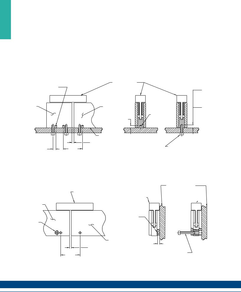
Magnet Way widths correspond to the mating coil assembly width.
Bottom Mounting Installation
Ø5 M6 (.197) DOWEL PIN 2 PER MAGNET WAY RECOMMENDED
64MM MAGNET WAY, REF.
Magnet Way assemblies are modular and come in standard lengths: 64, 128, 256, 512 mm.
COIL ASSEMBLY, REF.
|
4.9 |
|
(.193) |
|
M4 HARDWARE |
ADJACENT |
7.11 |
MAGNET WAY |
(.280) |
REF. |
M5 HARDWARE |
|
PIN, REF. |
5.33 (.210) |
|
4.83 (.190) |
|
|
|
CUSTOMER BANKING OR |
|
|
|
|
MOUNTING SURFACE, REF. |
|
|
|
|
RESULTANT GAP BETWEEN MAGNET |
|
|
7.01 |
46.00 |
ASSEMBLIES FROM PROPER PIN |
MOUNTING HARDWARE |
|
LOCATION. DO NOT BUTT MAGNET |
||||
(.276) |
(1.811) |
(SEE MAGNET ASSEMBLY |
||
ASSEMBLIES. |
||||
REF. |
REF. |
DRAWINGS FOR HARDWARE) |
||
|
Dimensions in mm (in)
Side mounting installation
COIL ASSEMBLY, REF.
64 MM MAGNET WAY, REF.
MOUNTING
SCREW, REF.
46.00
(1.811)
REF.
COIL ASSEMBLY, REF.
PIN, REF. Ø5 M6
2 REQ'D. FOR SIZE 64 (PINS OPTIONAL ON OTHER SIZE MAGNET WAYS)
ADJACENT MAGNET WAY
LENGHT OPTIONAL, REF.
RESULTANT GAP BETWEEN MAGNET
ASSEMBLIES FROM PROPER PIN LOCATION.
DO NOT BUTT MAGNET ASSEMBLIES.
Dimensions in mm (in)
30
CUSTOMER BANKING OR
MOUNTING SURFACE, REF.
COIL ASSEMBLY, REF. 
5.35 (.211)
4.85 (.191)
MOUNTING SCREW
(SEE MAGNET ASSEMBLY DRAWINGS FOR HARDWARE)
K O L L M O R G E N