

Linear Engine / DDL_Selection_Guide_en-EN_revA
.pdfNotes
S Y A W T E N G A M S S E L N O R I
w w w. k o l l m o r g e n . c o m |
31 |
|
|
|
|
A T A D E C N A M R O F R E P 5 0 D C I
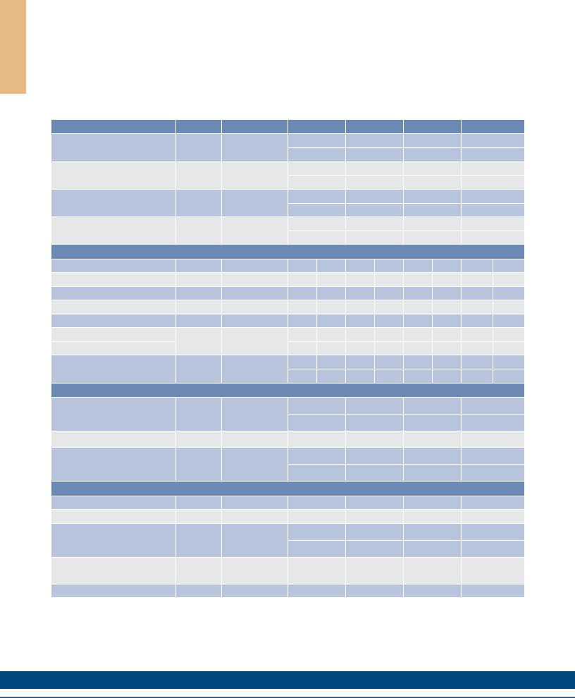
ICD05 Performance Data
Ironcore Motors Series
Rated Perfomance |
Symbol |
Units |
ICD05-030 |
ICD05-050 |
ICD05-075 |
ICD05-100 |
|||||
Peak Force |
Fp |
N |
|
165 |
|
295 |
|
441 |
|
588 |
|
lbf |
|
37.1 |
|
66.3 |
|
99.1 |
|
132 |
|||
|
|
|
|
|
|
||||||
Continuous Force @ Tmax (1) |
Fc |
N |
|
57.0 |
|
87.0 |
|
125 |
|
157 |
|
lbf |
|
12.8 |
|
19.6 |
|
28.1 |
|
35.3 |
|||
|
|
|
|
|
|
||||||
Motor Constant @ 130°C |
Km |
N/√W |
|
10.3 |
|
14.5 |
|
18.6 |
|
22.0 |
|
lbf/√W |
|
2.3 |
|
3.3 |
|
4.2 |
|
4.9 |
|||
|
|
|
|
|
|
||||||
Motor Constant @ 25°C |
Km25 |
N/√W |
|
12.3 |
|
17.2 |
|
22.0 |
|
26.0 |
|
lbf/√W |
|
2.8 |
|
3.9 |
|
4.9 |
|
5.9 |
|||
|
|
|
|
|
|
||||||
|
|
Electrical Specifications (2) |
|
|
|
|
|
|
|||
|
|
Winding Code |
A1 |
A5 |
A1 |
A5 |
A1 |
A5 |
A1 |
A5 |
|
Peak Current |
lp |
Arms |
7.9 |
13.7 |
8.5 |
14.7 |
8.5 |
14.7 |
8.5 |
14.7 |
|
Continuous Current @Tmax |
lc |
Arms |
2.1 |
3.7 |
2.0 |
3.4 |
1.9 |
3.3 |
1.8 |
3.1 |
|
Elextrical Resistance @ 25°C±10% |
Rm |
Ohms L-L |
3.2 |
1.1 |
4.5 |
1.5 |
6.1 |
2.0 |
7.7 |
2.6 |
|
ElectricalInductance ±20% |
L |
mh L-L |
9.1 |
3.0 |
14.4 |
4.8 |
21.0 |
7.0 |
27.6 |
9.2 |
|
Back EMFConstant |
Ke |
Vpeak/m/s L-L |
21.8 |
12.6 |
36.3 |
21.0 |
54.3 |
31.4 |
72.4 |
41.8 |
|
@25°C±10% |
Vpeak/in/sec L-L |
0.55 |
0.32 |
0.92 |
0.53 |
1.38 |
0.80 |
1.84 |
1.06 |
||
|
|||||||||||
Force Constant @ 25°C±10% |
Kf |
N/Arms |
26.7 |
15.4 |
44.5 |
25.7 |
66.5 |
38.4 |
88.7 |
51.2 |
|
lbf/Arms |
6.0 |
3.5 |
10.0 |
5.8 |
15.0 |
8.6 |
19.9 |
11.5 |
|||
|
|
||||||||||
|
|
Mechanical Specifications |
|
|
|
|
|
|
|||
Coil Assembly Mass ±15% |
Mc |
kg |
|
0.62 |
|
0.95 |
|
1.36 |
|
1.71 |
|
lbs |
|
1.4 |
|
2.1 |
|
3.0 |
|
3.8 |
|||
|
|
|
|
|
|
||||||
Magnetic Way Type |
|
|
MCD030 |
MCD050 |
MCD075 |
MCD100 |
|||||
Magnetic Way Mass ±15% |
Mw |
kg/m |
|
2.70 |
|
3.93 |
|
5.48 |
|
7.04 |
|
lbs/in |
|
0.15 |
|
0.22 |
|
0.31 |
|
0.39 |
|||
|
|
|
|
|
|
||||||
|
|
Figures of Merit and Additional Data |
|
|
|
|
|
||||
Electrical Time Constant |
Te |
ms |
|
2.9 |
|
3.2 |
|
3.4 |
|
3.6 |
|
Max.Theoretical Acceleration (3) |
Amax |
g’s |
|
28.0 |
|
30.2 |
|
31.9 |
|
32.8 |
|
Magnetic Attraction |
Fa |
kN |
|
0.53 |
|
0.89 |
|
1.33 |
|
1.78 |
|
lbf |
|
119 |
|
200 |
|
299 |
|
400 |
|||
|
|
|
|
|
|
||||||
Thermal Resistance (4) |
Rth |
°C/Watt |
|
3.50 |
|
2.90 |
|
2.30 |
|
2.06 |
|
(coils to external structure) |
|
|
|
|
|||||||
|
|
|
|
|
|
|
|
|
|
||
Max. Allowable Coil Temp. (4) |
Tmax |
°C |
|
130 |
|
130 |
|
130 |
|
130 |
|
Notes:
1.The motor continuous rated force is measured with the motor coils achieving the motor maximum allowable temperature Tmax.
2.Alternate windings can be made available. Please consult the Kollmorgen Customer Support for design options.
3.Maximum theoretical acceleration is based on the motors peak force and the motor mass alone. Limitations due to such factors as the additional mass of the load, the bearing type and design, the shock rating of the feedback, the peak current available from the amplifier etc. must be considered to determine the achievable acceleration in each application.
4.Please see our application sizing pages in the back of this guide for more details on sizing and thermal considerations.
32 |
K O L L M O R G E N |

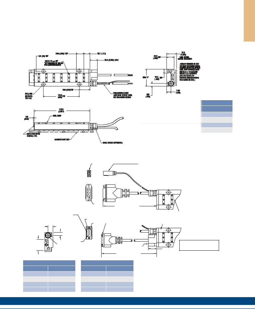
ICD05 Outline Drawings
|
|
|
|
|
|
|
|
|
|
|
|
|
|
|
|
|
|
15.7 |
|
|
|
|
|
|
|
|
|
|
|
|
|
|
|
|
|
|
|
|
|
|
|
|
|
|
|
|
|||
|
|
|
|
|
|
|
|
|
|
|
|
|
|
|
|
(.618) |
|
|
|
|
|
|||
6.0 (.24) |
24.0 (.945) |
|
|
|
|
|
|
|
|
|
|
26.8 |
(1.055) |
|
|
|||||||||
|
|
|
|
|
|
|
TYP |
|
|
|
|
|
|
|
|
|
|
|
MAX |
|
||||
TYP |
|
|
|
|
|
|
|
|
|
|
|
|
|
|
|
|
|
|
|
|
|
|
|
|
|
|
|
|
|
|
|
|
|
|
|
|
|
|
|
|
|
|
|
|
|
|
|
|
|
|
|
|
|
|
|
|
|
|
|
|
|
|
|
|
|
|
|
|
|
|
|
|
|
|
|
|
|
|
|
|
|
|
|
|
|
|
|
|
|
|
|
|
|
|
|
|
|
|
|
M2.5 PAN HEAD |
|
|
|
|
|
|
|
|
|
|
|
|
|
|
|
|
|
||
|
|
|
|
|
|
|
|
|
|
|
|
|
|
|
|
|
|
||
SCREW, 2 PL. |
|
|
|
|
|
|
|
|
|
|
|
|
|
|
|||||
|
|
|
|
|
|
30.2 |
|
|
|
|
|
|
|||||||
M2.5 X 3 mm DP |
|
|
|
|
|
|
|
(1.19) TYP |
|
|
|
|
|||||||
"N" NUMBER OF HOLES |
|
|
|
|
|
|
|
|
|
|
|||||||||
|
|
|
|
|
|
||||||||||||||
PER MOUNTING BAR |
|
|
|
|
|
|
42.8 (1.69) |
|
|
|
|
|
|||||||
|
|
|
|
|
|
10.3 |
|
|
|
|
|
|
|
|
|||||
|
|
|
|
|
|
|
|
|
|
TYP |
|||||||||
|
|
|
|
|
|
(Ø13/32) |
|
|
|
||||||||||
|
|
|
|
|
|
|
|
|
|
|
|
|
|
|
|
||||
|
|
|
|
|
|
TYP 4 PL |
|
|
|
|
|
|
|
|
|||||
|
|
|
|
|
|
|
|
|
|
|
|
99.0 |
|
|
|
|
|
|
|
2.0 |
|
|
|
|
|
|
|
|
|
|
|
(3.898) |
|
|
|
|
|
|
|
(.079) |
|
|
|
|
|
|
|
|
|
|
|
|
|
|
|
|
|
|
|
COIL ASSY |
|
|
|
|
|
|
|
|
|
|
|
|
|
|
|
|
|||
|
|
|
|
|
|
|
|
|
|
|
|
|
|
|
|||||
|
|
|
|
|
|
|
|
|
|
|
|
|
|
|
|
|
|
|
|
 FOR MOTOR CABLE AND HALL EFFECT MTG. SEE DRAWING BELOW
MAGNET WAY REF
HALL EFFECT (OPTIONAL)
Termination and Hall Effect Options
|
|
|
32.6 |
(1.283) |
|
23.2 REF |
MIN. REQ'D. |
||
|
MACH. ENVELOPE |
|||
|
(.913) |
|
|
|
|
|
|
AIRGAP SHOULD BE SET |
|
|
|
|
SO THAT SPECIFIED SHIM |
|
|
|
|
PASSES FREELY BETWEEN |
|
|
|
|
COIL AND MAGNET WAY: |
|
|
|
|
0.8±0.1mm w/o COVER |
|
|
|
|
0.6±0.1 mm w/COVER |
|
DIM 'X' |
|
|
(PLEASE REFER TO |
|
12.5 |
(.492) |
INSTALLATION MANUAL |
||
|
FOR MORE DETAIL.) |
|||
|
TYP |
|
|
|
|
|
|
14.0 |
|
9.0 |
|
|
(.551) |
|
|
|
|
|
|
(.355) |
|
|
|
|
Motor Coil |
Coil Width |
# Holes |
|
Type |
|
"X" |
"N" |
ICD05-030 |
|
55.0 (2.165) ± 1.0 (.04) |
3 |
ICD05-050 |
|
75.0 (2.953) ± 1.0 (.04) |
4 |
ICD05-075 100.0 (3.937) ± 1.0 (.04) |
5 |
||
ICD05-100 |
125.0 (4.921) ± 1.0 (.04) |
5 |
|
Notes:
1.Dimensions in mm (inches)
2.Tolerances unless otherwise specified: no decimal place ±0.8 (0.3)
X decimal place ±0.1 (.004)
XX decimal place ±0.05 (0.002)
|
PIN1 |
THERMAL PROTECTION CONNECTOR: |
|
|
|
2 PIN - MALE CONNECTOR |
|
|
1 |
FREE HANGING RECEPTACLE |
|
THERMAL |
MOLEX P/N 43025-0200 |
||
2 |
|||
2 FEMALE TERMINALS |
|||
|
|
||
|
|
MOLEX P/N 43030-0010 |
|
MOTOR |
|
|
|
HALL EFFECT CONNECTOR OPTION: |
|
|
|
POSITRONIC P/N: MD9M2000Z |
|
|
|
9 PIN, MALE |
PIN1 |
STANDARD LENGTH, |
|
MATING CONNECTOR REFERENCE: |
|
||
|
SEE TABLE |
||
POSITRONIC P/N: MD9F2000X |
|
||
|
|
||
SEE WIRE TABLE, PAGE 70 |
|
COIL ASSEMBLY REF |
|
|
PIN 5 |
#4-40 JACKNUT (2) |
|
|
9.0 |
PIN 9 |
COIL ASSEMBLY |
|
|
(REMOVABLE FOR |
|||
|
REF |
|||
14.0 |
(.355) |
|
BULKHEAD MOUNTING) |
|
|
|
|||
|
|
|
|
|
(.551) |
|
HALL |
|
|
|
|
|
|
|
|
|
EFFECT |
|
|
31.7 |
|
PIN1 |
|
|
|
|
|
|
|
(1.25) |
MOTOR CABLE |
|
|
|
|
|
HALL EFFECT ASSEMBLY |
26.8 |
|
|
|
|
||
|
|
|
STANDARD LENGTH, |
(1.055) |
|
|
|
MAX. |
|
|
|
|
SEE TABLE |
|
MATING CONNECTOR REFERENCE:
MOLEX "MICRO-FIT 3.0" PLUG: 43020-0201
MALE TERMINALS: 43031-0010 SEE WIRE TABLE, PAGE 70
MOTOR CONNECTOR:
POSITRONIC P/N: CBD3W3M0000Z 3 PIN, MALE SHELL, SIZE 2
MALE CONTACTS:
POSITRONIC P/N: MS40--D 3 REMOVABLE MALE CONTACTS, SIZE 8
MATING CONNECTOR REFERENCE:
POSITRONIC P/N: CBD3W3F0000X 3 FEMALE SOCKETS, SOLDER TYPE, SIZE 8, POSITRONIC P/N: FS40--D
SEE WIRE TABLE, PAGE 70
HALL EFFECT MASS
W/P* CONNECTOR: .07 KG (.15 LB) MAX W/C* CABLE: .03 KG (.07 LB) MAX
Connector Option
Connector |
Length |
|
P1 |
400 (16) |
|
P2 |
200 (8) |
|
P3 |
100 |
(4) |
P4 |
1200 |
(48) |
Flying Lead Option
Leads |
Length |
|
C1 |
400 (16) |
|
C2 |
200 (8) |
|
C3 |
100 |
(4) |
C4 |
1200 |
(48) |
Note:
Cables exiting motor and hall effects are not dynamic flex cables. For high life flex
extension cables, see page 72
w w w. k o l l m o r g e n . c o m |
33 |
S G N I W A R D E N I L T U O 5 0 D C I
A T A D E C N A M R O F R E P 0 1 D C I
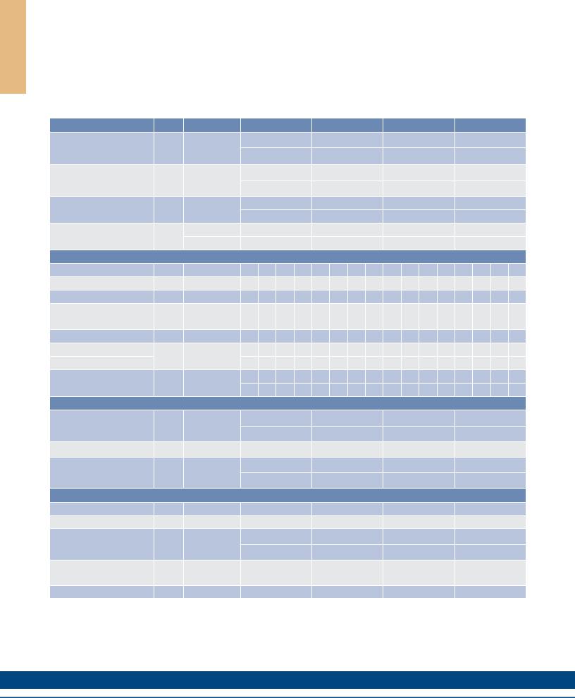
ICD10 Performance Data
Ironcore Motors Series
Rated Perfomance |
Symbol |
Units |
|
ICD10-030 |
|
|
ICD10-050 |
|
|
ICD10-075 |
|
|
ICD10-100 |
|
|||||
Peak Force |
Fp |
N |
|
330 |
|
|
550 |
|
|
824 |
|
|
1099 |
|
|||||
lbf |
|
74.2 |
|
|
124 |
|
|
185 |
|
|
247 |
|
|||||||
|
|
|
|
|
|
|
|
|
|
||||||||||
Continuous Force @ Tmax (1) |
Fc |
N |
|
104 |
|
|
171 |
|
|
246 |
|
|
315 |
|
|||||
lbf |
|
23.4 |
|
|
38.4 |
|
|
55.3 |
|
|
70.8 |
|
|||||||
|
|
|
|
|
|
|
|
|
|
||||||||||
Motor Constant @ 130°C |
Km |
N/√W |
|
14.6 |
|
|
20.5 |
|
|
26.4 |
|
|
31.3 |
|
|||||
lbf/√W |
|
3.3 |
|
|
4.6 |
|
|
5.9 |
|
|
7.0 |
|
|||||||
|
|
|
|
|
|
|
|
|
|
||||||||||
Motor Constant @ 25°C |
Km25 |
N/√W |
|
17.3 |
|
|
24.3 |
|
|
31.3 |
|
|
37.1 |
|
|||||
lbf/√W |
|
3.9 |
|
|
5.5 |
|
|
7.0 |
|
|
8.3 |
|
|||||||
|
|
|
|
|
|
|
|
|
|
||||||||||
|
|
Electrical Specifications (2) |
|
|
|
|
|
|
|
|
|
|
|||||||
|
|
Winding Code |
A1 |
A4 |
A5 |
A8 |
A1 |
A4 |
A5 |
A8 |
A1 |
A4 |
A5 |
A8 |
A1 |
A4 |
A5 |
A8 |
|
Peak Current |
lp |
Arms |
7.9 |
15.8 |
13.7 |
27.4 |
7.9 |
15.8 |
13.7 |
27.4 |
7.9 |
15.8 |
13.7 |
27.4 |
7.9 |
15.8 |
13.7 |
27.4 |
|
Continuous Current @Tmax |
lc |
Arms |
1.9 |
3.9 |
3.4 |
6.8 |
1.9 |
3.8 |
3.3 |
6.6 |
1.8 |
3.7 |
3.2 |
6.4 |
1.8 |
3.5 |
3.1 |
6.1 |
|
ElextricalResistance |
Rm |
Ohms L-L |
6.4 |
1.6 |
2.1 |
0.5 |
9.0 |
2.2 |
3.0 |
0.7 |
12.2 |
3.0 |
4.1 |
1.0 |
15.4 |
3.9 |
5.1 |
1.3 |
|
@ 25°C±10% |
|||||||||||||||||||
|
|
|
|
|
|
|
|
|
|
|
|
|
|
|
|
|
|
||
Electrical Inductance ±20% |
L |
mh L-L |
18.3 |
4.6 |
6.1 |
1.5 |
29.0 |
7.3 |
9.7 |
2.4 |
42.4 |
10.6 |
14.1 |
3.5 |
55.8 |
13.9 |
18.6 |
4.6 |
|
Back EMF Constant |
Ke |
Vpeak/m/s L-L |
43.7 |
21.8 |
25.2 |
12.6 |
72.8 |
36.4 |
42.0 |
21.0 109.2 54.6 |
63.1 |
31.5 145.7 72.8 |
84.1 |
42.0 |
|||||
@25°C±10% |
Vpeak/in/sec L-L |
1.11 0.55 0.64 0.32 1.85 0.92 1.07 |
0.53 2.77 1.39 1.60 0.80 3.70 1.85 2.14 1.07 |
||||||||||||||||
|
|||||||||||||||||||
Force Constant @ 25°C±10% |
Kf |
N/Arms |
53.5 |
26.8 |
30.9 |
15.4 |
89.2 |
44.6 |
51.5 |
25.7 |
134 |
66.9 |
77.2 |
38.6 |
178 |
89.2 |
103 |
51.5 |
|
lbf/Arms |
12.0 |
6.0 |
6.9 |
3.5 |
20.1 |
10.0 |
11.6 |
5.8 |
30.1 |
15.0 |
17.4 |
8.7 |
40.1 |
20.1 |
23.2 |
11.6 |
|||
|
|
||||||||||||||||||
|
|
Mechanical Specifications |
|
|
|
|
|
|
|
|
|
|
|||||||
Coil Assembly Mass ±15% |
Mc |
kg |
|
1.1 |
|
|
1.9 |
|
|
2.7 |
|
|
3.4 |
|
|||||
lbs |
|
2.5 |
|
|
4.1 |
|
|
5.9 |
|
|
7.5 |
|
|||||||
|
|
|
|
|
|
|
|
|
|
||||||||||
Magnetic Way Type |
|
|
|
MCD030 |
|
|
MCD050 |
|
|
MCD075 |
|
|
MCD100 |
|
|||||
Magnetic Way Mass ±15% |
Mw |
kg/m |
|
2.70 |
|
|
3.93 |
|
|
5.48 |
|
|
7.04 |
|
|||||
lbs/in |
|
0.15 |
|
|
0.22 |
|
|
0.31 |
|
|
0.39 |
|
|||||||
|
|
|
|
|
|
|
|
|
|
||||||||||
|
|
Figures of Merit and Additional Data |
|
|
|
|
|
|
|
|
|
||||||||
Electrical Time Constant |
Te |
ms |
|
2.9 |
|
|
3.2 |
|
|
3.5 |
|
|
3.6 |
|
|||||
Max.Theoretical Acceleration(3) |
Amax |
g’s |
|
30.7 |
|
|
30.7 |
|
|
32.5 |
|
|
33.7 |
|
|||||
Magnetic Attraction |
Fa |
kN |
|
1.06 |
|
|
1.78 |
|
|
2.66 |
|
|
3.56 |
|
|||||
lbf |
|
2.38 |
|
|
400 |
|
|
598 |
|
|
800 |
|
|||||||
|
|
|
|
|
|
|
|
|
|
||||||||||
Thermal Resistance (4) |
Rth |
°C/Watt |
|
2.05 |
|
|
1.52 |
|
|
1.21 |
|
|
1.04 |
|
|||||
(coils to external structure) |
|
|
|
|
|
|
|
|
|||||||||||
|
|
|
|
|
|
|
|
|
|
|
|
|
|
|
|
|
|
||
Max. Allowable Coil Temp. (4) |
Tmax |
°C |
|
130 |
|
|
130 |
|
|
130 |
|
|
130 |
|
|||||
Notes:
1.The motor continuous rated force is measured with the motor coils achieving the motor maximum allowable temperature Tmax.
2.Alternate windings can be made available. Please consult the Kollmorgen Customer Support for design options.
3.Maximum theoretical acceleration is based on the motors peak force and the motor mass alone. Limitations due to such factors as the additional mass of the load, the bearing type and design, the shock rating of the feedback, the peak current available from the amplifier etc. must be considered to determine the achievable acceleration in each application.
4.Please see our application sizing pages in the back of this guide for more details on sizing and thermal considerations.
34 |
K O L L M O R G E N |
ICD10 Outline Drawings
Termination and Hall Effect Options
PIN1
1
THERMAL 2
MOTOR
HALL EFFECT CONNECTOR OPTION: POSITRONIC P/N: MD9M2000Z
9 PIN, MALE PIN1
MATING CONNECTOR REFERENCE:
POSITRONIC P/N: MD9F2000X SEE WIRE TABLE, PAGE 70
|
|
PIN 5 |
|
9.0 |
PIN 9 |
14.0 |
(.355) |
|
|
|
|
(.551) |
|
HALL |
|
|
|
|
|
EFFECT |
31.7 |
|
PIN1 |
|
|
|
(1.25) |
MOTOR CABLE |
|
|
|
# Holes
"N"
3
4
5
5
in mm (inches)
unless otherwise specified: no decimal place ±0.8 (0.3)
X decimal place ±0.1 (.004)
XX decimal place ±0.05 (0.002)
THERMAL PROTECTION CONNECTOR:
2 PIN - MALE CONNECTOR
FREE HANGING RECEPTACLE MOLEX P/N 43025-0200
2 FEMALE TERMINALS
MOLEX P/N 43030-0010
STANDARD LENGTH,
SEE TABLE
|
COIL ASSEMBLY REF |
|
#4-40 JACKNUT (2) |
COIL ASSEMBLY |
|
(REMOVABLE FOR |
||
REF |
||
BULKHEAD MOUNTING) |
||
|
HALL EFFECT ASSEMBLY |
26.8 |
STANDARD LENGTH, |
(1.055) |
MAX. |
|
SEE TABLE |
|
MATING CONNECTOR REFERENCE:
MOLEX "MICRO-FIT 3.0" PLUG: 43020-0201
MALE TERMINALS: 43031-0010 SEE WIRE TABLE, PAGE 70
MOTOR CONNECTOR:
POSITRONIC P/N: CBD3W3M0000Z 3 PIN, MALE SHELL, SIZE 2
MALE CONTACTS:
POSITRONIC P/N: MS40--D 3 REMOVABLE MALE CONTACTS, SIZE 8
MATING CONNECTOR REFERENCE:
POSITRONIC P/N: CBD3W3F0000X 3 FEMALE SOCKETS, SOLDER TYPE, SIZE 8, POSITRONIC P/N: FS40--D
SEE WIRE TABLE, PAGE 70
HALL EFFECT MASS
W/P* CONNECTOR: .07 KG (.15 LB) MAX W/C* CABLE: .03 KG (.07 LB) MAX
Connector Option
Connector |
Length |
|
P1 |
400 (16) |
|
P2 |
200 (8) |
|
P3 |
100 |
(4) |
P4 |
1200 |
(48) |
Flying Lead Option
Leads |
Length |
|
C1 |
400 (16) |
|
C2 |
200 (8) |
|
C3 |
100 |
(4) |
C4 |
1200 |
(48) |
Note:
Cables exiting motor and hall effects are not dynamic flex cables. For high life flex
extension cables, see page 72
w w w. k o l l m o r g e n . c o m |
35 |
S G N I W A R D E N I L R U O 0 1 D C I
D C I
ICD MagnetWays
MCDxx-0064
Magnet assembiles are modular and can be installed in multiples of same or alternate lengths (see page 38). Standard assembly lengths are shown below.
S Y A W T E N G A M
|
|
63.3 ±.15 |
|
|
|
(2.492 ±.006) |
|
50.0 ±.05 |
|
|
|
(1.968 ±.002) |
|
|
|
25.0 |
|
|
Ø5.110-5.135 (.201-.202) |
|
|
THRU 2 PL. MARKED "A" |
|
(.984) |
|
|
|
|
5.0 |
FOR RECOMMENDED 5mm M6 |
|
|
|
||
|
|
LOCATING PINS |
|
6.65 |
|
(.197) |
|
|
|
||
(.262) |
A |
A |
|
|
|
||
|
|
|
STAINLESS STEEL MAGNET COVER |
Ø4.7 (.185) THRU |
+0.25 |
|
|
|
C'BORE 8.3 (.327) X 1.6 |
-0.00(.063) DP. |
"W2" |
|
|
2 PL. LOCATED AS SHOWN |
|
|||
±.08 |
"W" |
|||
RECOMMENDED MOUNTING HARDWARE: |
||||
(.003) |
±.25(0.010) |
|||
M4 SOCKET CAP DIN 912 |
|
|||
|
|
|
||
8-32 SOCKET CAP SCREW |
|
|
||
|
|
|
|
|
|
|
|
|
|
|
Type |
|
"J" |
|
|
|
"H" ±.25(0.010) |
|
Dimensions in mm (in) |
||
|
|
|
|
|
||||||
"W" |
"W2" |
|
|
"J" |
H" |
|||||
|
|
|
||||||||
MCD030-0064-001 |
55.0 (2.165) |
45.0 (1.772) |
4.0 (.157) |
8.25 (.325) |
|
|||||
MCD050-0064-001 |
75.0 (2.953) |
65.0 (2.559) |
4.0 (.157) |
8.25 (.325) |
|
|||||
MCD075-0064-001 |
100.0 (3.937) |
90.0 (3.543) |
4.0 (.157) |
8.25 (.325) |
|
|||||
MCD100-0064-001 |
125.0 (4.921) |
115.0 (4.528) |
4.0 (.157) |
8.25 (.325) |
|
|||||
MCDxx-0128
Ø4.7 (.185) THRU |
+0.25 |
C'BORE 8.3 (.327) X 1.6 |
-0.00(.063) DP. |
4 PL. LOCATED AS SHOWN RECOMMENDED MOUNTING HARDWARE: M4 SOCKET CAP DIN 912
8-32 SOCKET CAP SCREW
|
127.3 |
±.15 |
Ø5.110-5.135 (.201-.202) |
|
(5.012 |
±.006) |
|
|
THRU 2 PL. MARKED "A" |
||
6.65 |
|
|
|
|
|
FOR RECOMMENDED 5MM M6 |
|
(.262) |
114.0 |
±.05 |
LOCATING PINS |
|
|
||
|
(4.488 |
±.002) |
5.0 |
25.0 |
|
|
|
|
|
(.197) |
|
(.984) |
|
|
|
|
A |
A |
|
|
|
|
STAINLESS STEEL MAGNET COVER |
|
|
"W2" |
|
|
|
±.08 |
"W" |
|
|
(.003) |
±.25 |
|
|
|
(0.010) |
|
64.0 |
|
|
|
(2.520) |
|
|
|
2 PL. |
|
|
|
|
|
|
|
|
|
|
|
|
|
|
|
|
|
|
Type |
|
"J" |
|
|
|
|
|
"H" ±.25 (0.010) |
|
|
Dimensions in mm (in) |
||||
|
|
|
|
|
|
||||||||||
"W" |
"W2" |
|
|
|
"J" |
H" |
|||||||||
|
|
|
|
||||||||||||
MCD030-0128-001 |
55.0 (2.165) |
45.0 (1.772) |
4.0 (.157) |
|
8.25 (.325) |
|
|||||||||
MCD050-0128-001 |
75.0 (2.953) |
65.0 (2.559) |
4.0 (.157) |
|
8.25 (.325) |
|
|||||||||
MCD075-0128-001 |
100.0 (3.937) |
90.0 (3.543) |
4.0 (.157) |
|
8.25 (.325) |
|
|||||||||
MCD100-0128-001 |
125.0 (4.921) |
115.0 (4.528) |
4.0 (.157) |
|
8.25 (.325) |
|
|||||||||
|
|
|
|
|
|
|
|
|
|
|
|
|
|
|
|
36 |
|
|
|
|
|
|
|
|
|
|
|
|
|
|
K O L L M O R G E N |
|
|
|
|
|
|
|
|
|
|
|
|
|
|
|
|
|
|
|
|
|
|
|
|
|
|
|
|
|
|
|
|

MCDxx-0256
|
|
|
|
|
|
Ø5.110-5.135 (.201-.202) |
|
|
|
255.3 |
± .15 |
|
THRU 2 PL. MARKED "A" |
|
|
|
|
FOR RECOMMENDED 5mm M6 |
||
|
|
|
(10.051 |
± .006) |
|
|
|
|
|
|
LOCATING PINS |
||
|
|
|
|
242.0 |
.05 |
|
|
|
|
25.0 |
|
||
|
|
6.65 |
(9.528 |
.002) |
5.0 (.197) |
|
|
|
(.984) |
|
|
|
|
|
|
(.262) |
A |
|
A |
|
|
|
|
|
|
||
|
|
|
|
|
"W2" |
|
|
|
|
|
|
± .08 |
|
|
|
|
|
|
(.003) |
STAINLESS STEEL MAGNET COVER |
|
|
|
|
|
|
"W" |
|
|
|
|
|
|
± .25 |
Ø4.7 (.185) THRU |
+0.25 |
|
|
|
|
(0.010) |
C'BORE 8.3 (.327) X 1.6 |
(.063) DP. |
|
|
|
|
|
-0.00 |
|
|
|
|
||
8 PL. LOCATED AS SHOWN |
|
|
|
|
|
|
RECOMMENDED MOUNTING HARDWARE: |
|
64.0 |
|
|
||
M4 SOCKET CAP DIN 912 |
|
|
(2.520) |
|
|
|
8-32 SOCKET CAP SCREW |
|
|
6 PL. |
|
|
|
|
|
"J" |
"H" ±.25 (0.010) |
|
|
|
Type |
"W" |
"W2" |
"J" |
H" |
Dimensions in mm (in) |
|
|||||
MCD030-0256-001 |
55.0 (2.165) |
45.0 (1.772) |
4.0 (.157) |
8.25 (.325) |
|
MCD050-0256-001 |
75.0 (2.953) |
65.0 (2.559) |
4.0 (.157) |
8.25 (.325) |
|
MCD075-0256-001 |
100.0 (3.937) |
90.0 (3.543) |
4.0 (.157) |
8.25 (.325) |
|
MCD100-0256-001 |
125.0 (4.921) |
115.0 (4.528) |
4.0 (.157) |
8.25 (.325) |
|
MCDxx-0512
|
511.3 |
±.15 |
|
|
|
Ø5.110-5.135 (.201-.202) |
|
(20.130 ±.006) |
498.0 ±.05 |
|
|
THRU 2 PL. MARKED "A" |
|
|
|
|
|
|
FOR RECOMMENDED 5mm M6 |
|
|
|
|
(19.606 ±.002) |
|
5.0 |
|
|
25.0 |
|
|
LOCATING PINS |
||
|
|
|
|
(.197) |
|
|
6.65 |
(.984) |
|
|
|
|
|
|
|
|
|
|
||
(.262) |
A |
|
|
|
A |
|
|
|
|
|
|
||
|
|
|
|
|
|
STAINLESS STEEL |
|
|
|
|
|
"W2" |
MAGNET COVER |
|
|
|
|
|
|
|
|
|
|
|
|
±.08 |
"W" |
|
|
|
|
|
(0.003) |
±.25 |
|
|
|
|
|
|
(0.010) |
|
64.0 |
|
Ø4.7 (.185) THRU |
+0.25 |
|
|
|
(2.520) |
|
C'BORE 8.3 (.327) X 1.6 |
(.063) DP. |
|
|
|
|
-0.00 |
|
|||
|
14 PL. |
|
16 PL. LOCATED AS SHOWN |
|
||
|
|
|
RECOMMENDED MOUNTING HARDWARE: |
|
||
|
|
|
M4 SOCKET CAP DIN 912 |
|
|
|
|
|
|
8-32 SOCKET CAP SCREW |
|
|
|
|
|
|
|
|
"J" |
|
|
|
|
"H" ±.25 (0.010) |
|
||
Type |
"W" |
"W2" |
"J" |
H" |
Dimensions in mm (in) |
|
|||||
MCD030-0512-001 |
55.0 (2.165) |
45.0 (1.772) |
4.0 (.157) |
8.25 (.325) |
|
MCD050-0512-001 |
75.0 (2.953) |
65.0 (2.559) |
4.0 (.157) |
8.25 (.325) |
|
MCD075-0512-001 |
100.0 (3.937) |
90.0 (3.543) |
4.0 (.157) |
8.25 (.325) |
|
MCD100-0512-001 |
125.0 (4.921) |
115.0 (4.528) |
4.0 (.157) |
8.25 (.325) |
|
S Y A W T E N G A M D C I
w w w. k o l l m o r g e n . c o m |
37 |
|
|
|
|
S Y A W T E N G A M D C I
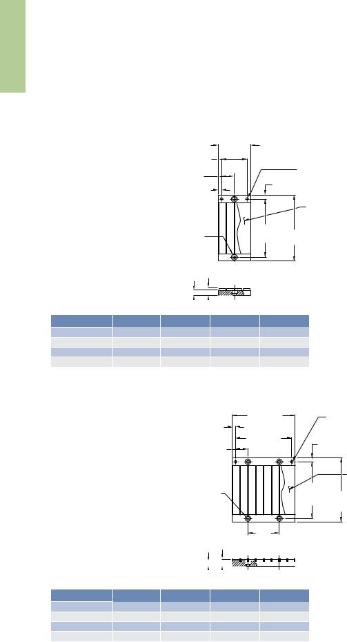
ICD MagnetWays
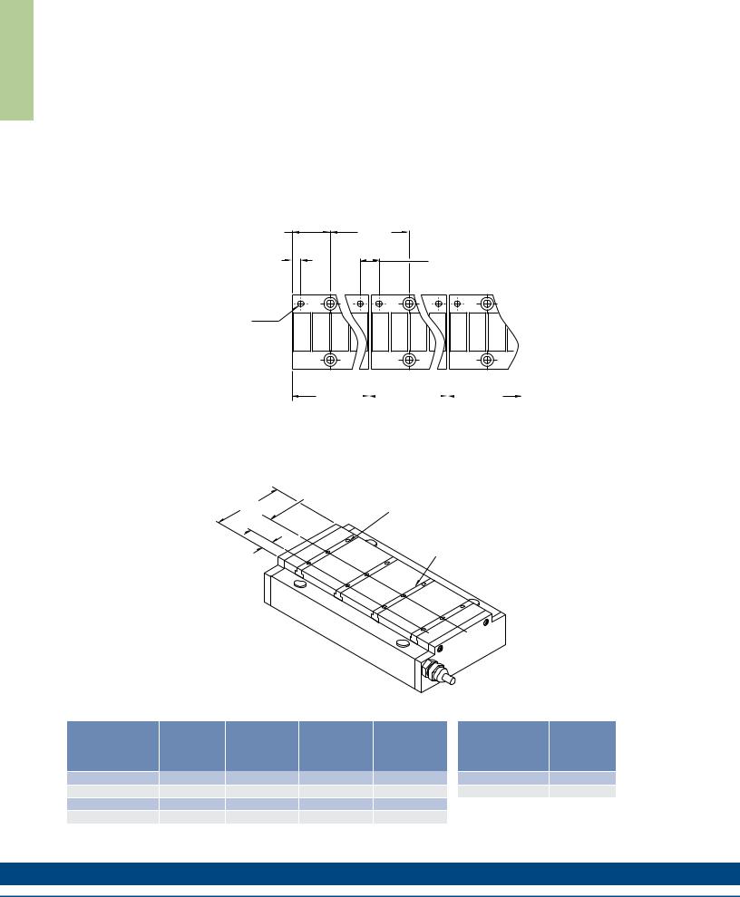
Typical Installation of Multiple Ironcore Magnet Assemblies
Magnet Way widths correspond to the mating coil assembly width. Magnet Way assemblies are modular and come in standard lengths: 64, 128, 256, 512 mm. Multiple magnet assemblies can be installed to obtain the desired length.
Shown below is the method to mount multiple assemblies.
|
|
|
64.0 |
|
|
31.75 |
|
|
(2.520) |
|
|
(1.250) |
|
TYP BOLT MTG. |
|
|
|
|
|
|
|
|
14.00 |
6.75 |
|
|
|
|
(.551) |
(.266) |
|
|
|
|
PIN LOC. |
|
|
|
|
RECOMMENDED |
|
|
|
|
|
PIN Ø5 M6 |
|
PIN DATUM HOLES TO BE LOCATED ON |
|
|
|
|
|
SAME SIDE TO ENSURE CORRECT |
A |
A |
A |
A |
A |
NORTH/SOUTH POLE ORIENTATION |
|
|
|
|
|
1ST |
|
2ND |
|
|
3RD |
||
MAGNET |
|
|
MAGNET |
|
|
|
MAGNET |
|
|
|
|
||||
ASSEMBLY |
|
ASSEMBLY |
|
|
ASSEMBLY |
||
Dimensions in mm (in)
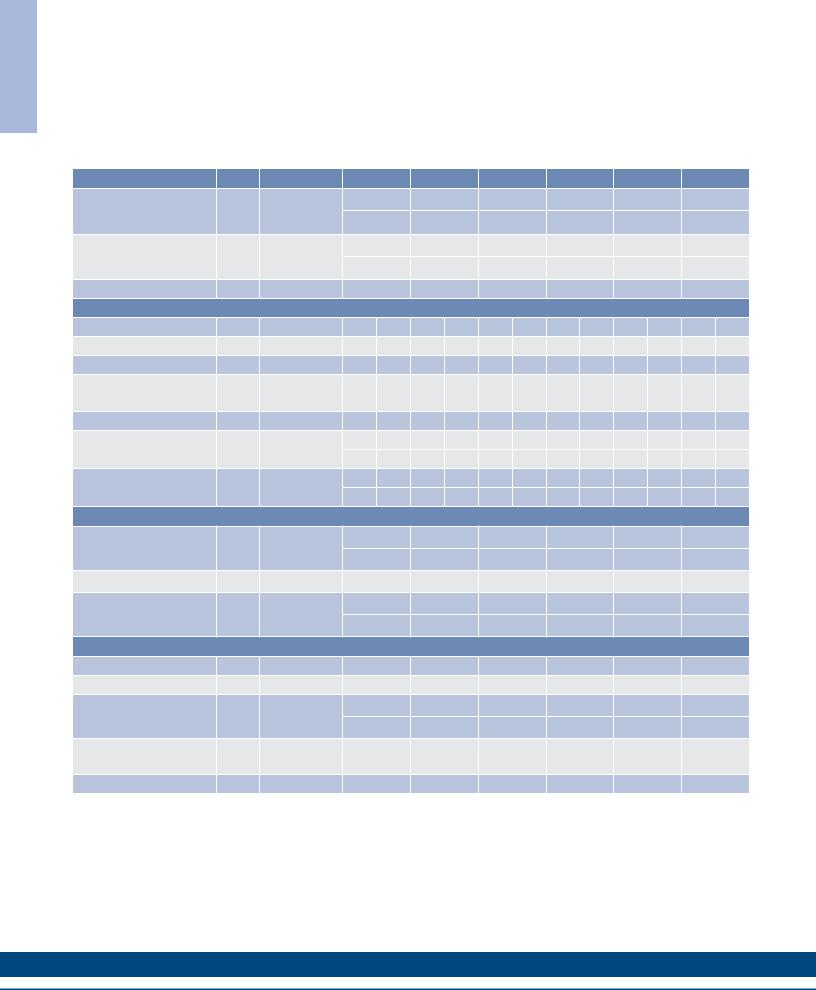
Typical Mounting Bar Lengths & Mounting Holes Tabulation
"C"
"L"
M2.5 x 0.45 x 3 MM DP NUMBER OF HOLES "N" PER MOUNTING BAR
NUMBER OF
"S" MOUNTING "T" BARS "M"
Dimensions in mm (in)
Motor Coil |
Number |
Spacing |
Mounting |
|
|
of Holes |
Between Holes |
Bar Length |
|
||
Type |
|
||||
"N" |
"C" |
"L" |
"S" |
||
|
|||||
ICDXX-030 |
3 |
12.0 (.472) |
30 (1.18) |
3.0 (.118) |
|
ICDXX-050 |
4 |
12.0 (.472) |
50 (1.97) |
7.0 (2.76) |
|
ICDXX-075 |
5 |
16.0 (.630) |
75 (2.95) |
5.5 (.217) |
|
ICDXX-100 |
5 |
20.0 (.787) |
100 (3.94) |
10.0 (.394) |
Motor Coil
Number
Type
of Bars
"M"
ICD05-XXX 4
ICD10-XXX 7
38 |
K O L L M O R G E N |

Notes
S Y A W T E N G A M D C I
w w w. k o l l m o r g e n . c o m |
39 |
|
|
|
|
A T A D E C N A M R O F R E P 1 1 C I
IC11 Performance Data
Ironcore Non-Cooled Motors Series
Rated Perfomance |
Symbol |
Units |
IC11-030 |
IC11-050 |
IC11-075 |
IC11-100 |
IC11-150 |
IC11-200 |
|||||||
Peak Force |
Fp |
N |
320 |
533 |
800 |
1067 |
1600 |
2135 |
|||||||
lbf |
71.9 |
120 |
|
180 |
240 |
360 |
480 |
|
|||||||
|
|
|
|
||||||||||||
Continuous Force @ Tmax (1) |
Fc |
N |
144 |
263 |
413 |
574 |
861 |
1197 |
|||||||
lbf |
32.4 |
59.1 |
92.8 |
129 |
194 |
|
269 |
|
|||||||
|
|
|
|
||||||||||||
Motor Constant @ 25°C |
Km |
N/√W |
22.5 |
32.0 |
41.4 |
49.1 |
62.0 |
73.0 |
|||||||
|
|
Electrical Specifications (2) |
|
|
|
|
|
|
|
||||||
|
|
Winding Code |
A1 |
A5 |
A1 |
A5 |
A1 |
A5 |
A1 |
A5 |
A1 |
A5 |
A1 |
A5 |
|
Peak Current |
lp |
Arms |
11.3 |
19.1 |
11.3 |
19.1 |
11.3 |
19.1 |
11.3 |
19.1 |
11.3 |
19.1 |
11.3 |
19.1 |
|
Continuous Current @Tmax |
lc |
Arms |
4.0 |
6.9 |
4.4 |
7.6 |
4.6 |
8.0 |
4.8 |
8.2 |
4.8 |
8.3 |
5.0 |
8.6 |
|
ElextricalResistance |
Rm |
Ohms L-L |
1.9 |
0.63 |
2.6 |
0.87 |
3.5 |
1.2 |
4.4 |
1.5 |
6.2 |
2.1 |
8.0 |
2.7 |
|
@ 25°C±10% |
|||||||||||||||
|
|
|
|
|
|
|
|
|
|
|
|
|
|
||
Electrical Inductance ±20% |
L |
mh L-L |
16.7 |
5.6 |
26.7 |
8.9 |
39.4 |
13.1 |
52.0 |
17.3 |
77.3 |
25.8 |
103 |
34.2 |
|
Back EMF Constant |
Ke |
Vpeak/m/s L-L |
30.9 |
17.8 |
51.4 |
29.7 |
77.1 |
44.5 |
103 |
59.3 |
154 |
89.0 |
206 |
119 |
|
@25°C±10% |
Vpeak/in/sec L-L |
0.78 |
0.45 |
1.30 |
0.75 |
1.96 |
1.13 |
2.61 |
1.51 |
3.92 |
2.26 |
5.22 |
3.02 |
||
|
|||||||||||||||
Force Constant @ 25°C±10% |
Kf |
N/Arms |
37.8 |
21.8 |
62.9 |
36.3 |
94.4 |
54.5 |
126 |
72.7 |
189 |
109 |
252 |
145 |
|
lbf/Arms |
8.5 |
4.9 |
14.1 |
8.2 |
21.2 |
12.3 |
28.3 |
16.3 |
42.4 |
24.5 |
56.6 |
32.7 |
|||
|
|
||||||||||||||
|
|
|
Mechanical Specifications |
|
|
|
|
|
|
|
|
||||
Coil Assembly Mass ±15% |
Mc |
kg |
|
2.5 |
3.6 |
|
|
5.0 |
|
6.5 |
9.4 |
|
12.3 |
||
lbs |
|
5.5 |
7.9 |
|
11.0 |
14.3 |
20.7 |
27.1 |
|||||||
|
|
|
|
||||||||||||
Magnetic Way Type |
|
|
MC030 |
MC050 |
MC075 |
MC100 |
MC150 |
MC200 |
|||||||
Magnetic Way Mass ±15% |
Mw |
kg/m |
|
5.4 |
7.5 |
|
10.1 |
12.7 |
20.7 |
26.8 |
|||||
lbs/in |
0.30 |
0.42 |
0.56 |
0.71 |
1.16 |
1.50 |
|||||||||
|
|
||||||||||||||
|
|
Figures of Merit and Additional Data |
|
|
|
|
|
|
|||||||
Electrical TimeConstant |
Te |
ms |
|
8.8 |
10.3 |
11.3 |
11.8 |
12.5 |
12.8 |
||||||
Max.Theoretical Acceleration(3) |
Amax |
g’s |
15.3 |
17.7 |
19.2 |
19.6 |
20.3 |
20.7 |
|||||||
Magnetic Attraction |
Fa |
kN |
|
1.4 |
2.4 |
|
|
3.7 |
|
4.9 |
7.3 |
|
9.9 |
|
|
lbf |
324 |
546 |
|
821 |
1102 |
1639 |
2214 |
||||||||
|
|
|
|||||||||||||
Thermal Resistance (4) |
Rth |
°C/Watt |
1.64 |
0.99 |
0.67 |
0.50 |
0.35 |
0.25 |
|||||||
(coils to external structure) |
|||||||||||||||
|
|
|
|
|
|
|
|
|
|
|
|
|
|
||
Max. Allowable Coil Temp. (4) |
Tmax |
°C |
130 |
130 |
|
130 |
130 |
130 |
|
130 |
|
||||
Notes:
1.The motor continuous rated force is measured with the motor coils achieving the motor maximum allowable temperature Tmax.
2.Alternate windings can be made available. Please consult the Kollmorgen Customer Support for design options.
3.Maximum theoretical acceleration is based on the motors peak force and the motor mass alone. Limitations due to such factors as the additional mass of the load, the bearing type and design, the shock rating of the feedback, the peak current available from the amplifier etc. must be considered to determine the achievable acceleration in each application.
4.Please see our application sizing pages in the back of this guide for more details on sizing and thermal considerations.
40 |
K O L L M O R G E N |