

Linear Engine / BR1202-G
.pdfLinear Mot
and Stages
Linear Motors and Stages
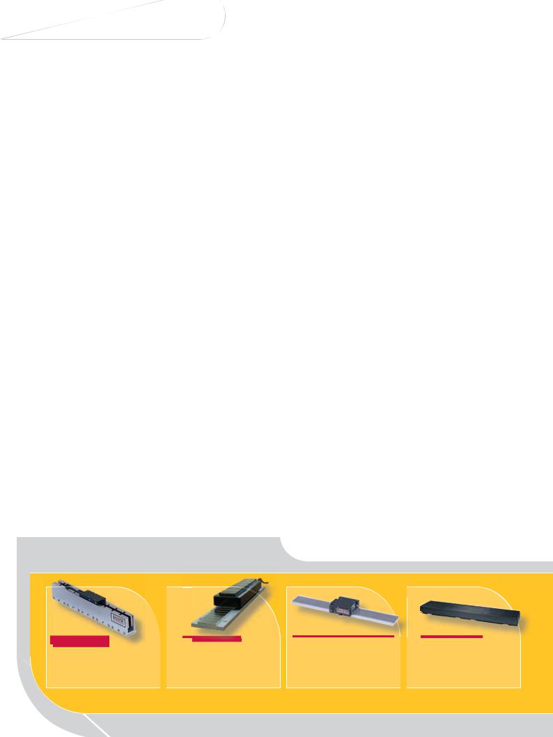
Linear Motor Solutions
Baldor provides industry with the widest range of linear motors, linear stages and controls. Being a leader in linear motor design and manufacturing, Baldor continually develops advanced products and innovations to meet a variety of linear motion applications.
Linear motors provide unique speed and positioning performance advantages. Linear motors provide direct-coupled motion and eliminate mechanical transmission devices. The rugged mechanical design provides accurate motion and precision positioning for hundreds of millions of cycles. Baldor linear motors and stages are used in thousands of successful applications worldwide.
Some advantages of linear products include, higher linear velocities, non-wearing moving part, and direct linear motion without mechanical linkages, therefore no backlash. Other advantages are:
›High repeatability – resolution to 0.1 microns [0.000004 inch] – all parts produced are identical
›Highly accurate – to 2.5 micron/300 mm [0.0001 inch/ft] – provides precision in the operation
›No backlash – direct drive has no backlash - this improves accuracy of the part or operation
›Faster acceleration – from 1 to over 10 g’s – this leads to shortened cycle times and improved productivity.
›Higher velocities – speeds to over 8 meters/sec [300 inches/sec] – to position the payload faster
›Long term reliability – only two parts with only one moving part – this leads to simplicity and improves the applications reliability
›No wear or maintenance – no contacting parts, thus reducing component friction and wear
›Ease of Installation – linear motors are designed to allow for alignment tolerances. Misalignment produces no degradation of performance.
›Clean Room compatibility – can be customized to meet most clean rooms
|
Page 11 |
Page 15 &19 |
Page 22 |
Cog-free Brushless |
Iron-Core Brushless |
Single & Dual- |
AC Induction Motor |
High performance linear motor |
High performance linear motor |
Axis Steppers |
High performance linear |
|
|
Open loop stepper motor |
induction motor |
|
|
|

Typical Applications:
› |
Baggage Handling |
› MRI & X Ray Equip |
|
› |
Bottle Labeling |
› |
Packaging Machinery |
› |
Coordinate Measurement |
› |
Part Transfer Systems |
› |
Diagnostic Probe |
› |
PCB Assembly/Inspection |
› |
Disk Certifier |
› |
PCB Drilling |
› |
Electronic Assembly |
› Pick & Place Systems |
|
› |
Food Processing |
› |
Precision Grinding |
› |
Inspection Equipment |
› |
Printing Application |
› |
Laser Cutting Machines |
› |
Robotic Applications |
› |
Laser Surgery Machine |
› |
Semiconductor |
› |
Machine Tool |
› |
Sorting Machines |
› |
Mail Sorting |
› |
Surface Mount Assembly |
› |
Material Handling |
› |
Wafer Etch Machines |
› |
Medical |
› |
Vision Inspection |
Page 27 |
Page 29 |
Page 33 |
Linear Motors |
Linear Stages |
Engineering Information |
Other linear motor technology |
High performance linear stages |
Linear Motors and Stages
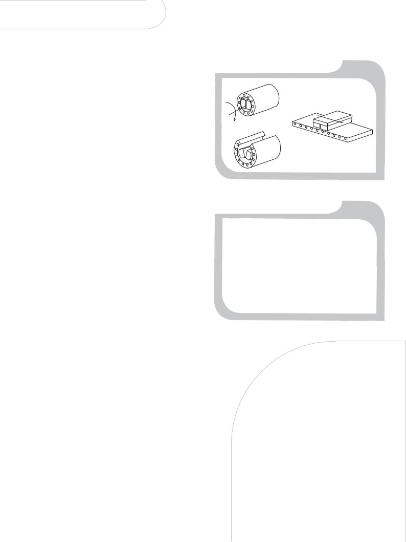
What is a Linear Motor
The same electromagnetic force that produces torque in a rotary motor also produces direct force in a linear motor. For example, a permanent magnet DC linear motor is similar to a permanent magnet DC rotary motor and an AC induction linear motor is similar to a squirrel cage induction motor.
Take a rotary motor, split it radially along its axis of rotation and flatten it out. The result is a flat linear motor that produces direct linear force instead of torque. It follows that linear motors utilize the same controls as rotary motors. And similar to a rotary motor with rotary encoders, linear motor positioning is provided by a linear encoder.
Variety of Linear Motor Technologies
As there are a variety of motor technologies available in the rotary world, there are a variety of technologies in the linear world. These include brushless, cog-free, permanent magnet, brush-type, induction and steppers. There are also custom linear products such as polynoids, moving magnets and moving coils. Each technology brings advantages to the application.
Linear Motors and Stages
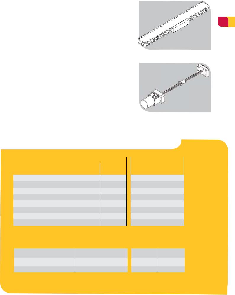
Linear motors consist of two parts – a stationary track or “platen” and a moving “forcer”. They can be provided as a stand-alone linear motor assembly or as a complete stage
– built with a housing or enclosure with linear bearings, limit switches, cable track/carrier, protective bellows and linear encoder in a wide variety of lengths.
Selecting the Correct Drive
Linear motors typically produce a peak force three times continuous force. Some drives are rated at only two times so this must be taken into consideration when sizing the drive for the motor.
Baldor produces the widest range of linear motors and stages. Contact us and let Baldor assist you in selecting the linear motor technology best suited for your application, to deliver optimum machine performance in your application. Baldor also has drives and motion controllers for powering and positioning of linear motors.
Imaginary process of unrolling a rotary motor
N S
 TORQUE
N |
S |
FORCE |
|
N S
Tubular non-commutated DC Linear Motor
The Benefits of Linear Motors
Over Traditional Technologies
5
›Direct drive, zero backlash for higher accuracy
›Non-contact, non-wearing for enhanced reliability
›Simplicity, no mechanical linkages provides faster installation
›High acceleration and velocity reduces cycle times
›High accuracy and repeatability provides better quality control
›Low maintenance and long life lowers cost of ownership
›Longer lengths with no performance degradation
Linear Motor > Higher Through Put > Higher Productivity
Material Comparison Between Linear Motors and Ballscrews/Timing Belts
|
Closed loop |
Open loop |
||
|
Ballscrew with |
Linear Motor |
Timing Belt with |
Linear Motor |
|
Rotary Motor |
Rotary Stepper |
||
|
|
|
||
Rotary to Linear Mechanism |
|
|
|
|
Motor Mount |
|
|
|
|
Nut Mount |
|
|
|
|
Coupling |
|
|
|
|
End Bearing |
|
|
|
|
Motor |
|
|
|
|
Encoder (linear) |
|
|
|
|
Rails (+ Bearings) |
|
|
|
|
Required Not Required
>Performance comparison
Max. Speed m/s [ips] |
1 [38] |
10+ [400+] |
2.5 [100] |
10+ [400+] |
Max. Accel. |
20 m/s2 (2g) |
98+ m/s2 (10+g) |
20 m/s2 (2g) |
98+ m/s2 (10+g) |
Repeatability µm (inch) |
50(0.002)* |
1(0.00004)** |
250 [0.001] |
10 [0.0004] |
* Dependent on ball screw pitch, resolution and feedback ** Dependent on encoder specification
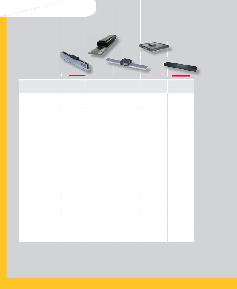
Linear Motors and Stages
> Linear Motor Characteristics Overview
Page 8 Page 11 Page 15 Page 19
Motor Series
Continuous
Force
Peak Force @
10% Duty
Acceleration
Maximum
Speed
Maximum
Stroke
Accuracy
Repeatability
Positioning Type
Drive/Control
Load Support
N
Lbs
N
Lbs
(3) m/s2 g’s
m/s
in/sec
m in
(1) μm/ 300mm (4) in/ft
(1) μm (4) in
Cog-free |
Iron Core |
Single Axis |
Dual Axis |
|
Brushless LMCF |
Brushless LMIC |
Stepper LMSS (7) |
Stepper LMDS (7) |
|
5.3 - 771 |
80 - 5179 |
10 - 240 |
15 - 134 |
|
1.2 - 173 |
18 - 1164 |
2.2 - 65 (5) |
3.3 - 30 (5) |
|
16 - 2300 |
213 - 13813 |
10 - 240 |
15 - 134 |
|
3.6 - 517 |
48 - 3105 |
2.2 - 65 (6) |
3.3 - 30 (6) |
|
98 |
98 |
9.8 |
9.8 |
|
10 |
10 |
1 |
1 |
|
10 |
8 |
2 |
1.5 |
|
400 |
328 |
80 |
60 |
|
Unlimited |
Unlimited |
Unlimited |
1.0 x 2.7 |
|
42 x 106 |
||||
|
|
|
||
5 |
5 |
25 |
25 |
|
0.0002 |
0.0002 |
0.001 |
0.001 |
|
1 |
1 |
10 |
5.08 |
|
0.00004 |
0.00004 |
0.0004 |
0.0002 |
|
Closed Loop |
Closed Loop |
Open or Closed |
Open Loop |
|
Loop |
||||
|
|
|
||
3-Phase |
3-Phase |
Stepper Motor |
Stepper Motor |
|
Brushless Control |
Brushless Control |
Drive |
Drive |
|
Customer |
Customer |
Roller or Air |
Air Bearing |
|
Supplied Bearing |
Supplied Bearing |
Bearing |
||
|
Notes: All specifications are for reference only.
(1) |
Encoder dependent |
(5) |
Force @ 1 m/sec (40 in/sec) |
(2) |
Vector control required. Encoder dependent |
(6) |
Static force |
(3) |
Acceleration is dependent on amount of mass attached |
(7) |
Continuous and Peak Force |
(4) |
Accuracy and repeatability are referenced against a laser interferometer. |
|
for Steppers are the same |
|
Tighter tolerances are available. |
|
|
AC Induction
LMAC
62 - 445
14 - 100
311 - 2224
(15% Duty)
70 - 500
9.8
1
6.8[270] @ 60 Hz
50.8[2000] @ 40 Hz
Unlimited
2.5
0.0001
1
0.00004 (2)
Open or Closed Loop
Single or 3 Phase AC Line or Adjustable Speed
Customer
Supplied
Bearings

Motor Series
Continuous
Force
Peak Force @
10% Duty
Acceleration
Maximum
Speed
Maximum
Stroke
Accuracy
Repeatability
Positioning Type
Drive/Control
Load Support
|
Page 27 |
Page 27 |
Page 27 |
|
|
Non- |
Non- |
DC Brushed |
|
|
Commucated |
Commucated |
Linear Servo |
|
|
DC LMNM |
DC LMNC |
LMBR |
|
N |
3 - 223 |
3 - 41 |
18.7 - 244.8 |
|
Lbs |
0.5 - 50 |
0.625 - 9 |
4.2 - 55 |
|
N |
7 - 668 |
9 - 121 |
57.9 - 761.0 |
|
Lbs |
1.5 - 150 |
1.875 - 27 |
13 - 171 |
|
(3) m/s2 |
98 |
98 |
49 |
|
g’s |
10 |
10 |
5 |
|
m/s |
1 |
0.5 |
1.9 |
|
in/sec |
40 |
20 |
75 |
|
m |
0.05 |
0.013 |
3.2 |
|
in |
2.0 |
0.5 |
11 |
|
(1) μm/ |
2.5 |
5 |
5.0 |
|
300mm |
||||
0.0001 |
0.0002 |
0.0002 |
||
(4) in/ft |
||||
|
|
|
||
(1) μm |
1 |
1 |
1 |
|
(4) in |
0.00004 |
0.00004 |
0.00004 |
|
|
Open or Closed |
Open or Closed |
Closed Loop |
|
|
Loop |
Loop |
||
|
|
|||
|
DC Servo Drive |
DC Servo Drive |
PWM Brushed |
|
|
Servo Drive |
|||
|
|
|
||
|
Jewel Sapphire or |
N/A |
Customer |
|
|
Ball Bushing |
Supplied Bearing |
||
|
|
7
Page 28 |
Page 28 |
|
Polynoid Linear |
HyCore Linear |
|
Motor LMPY |
Motor LMHS |
|
4 |
- 90 |
53 - 465 |
1 |
- 20 |
12 - 105 |
22 |
- 240 |
95 - 800 |
5 |
- 54 |
21 - 180 |
9.829.4
1 |
3 |
|
2.3 |
1.5 |
|
90 |
60 |
|
Limited |
Limited |
|
by end stops |
by end stops |
|
and support |
and support |
|
N/A |
5 |
|
0.0002 |
||
|
||
N/A |
1 |
|
0.00004 |
||
|
||
Open or Closed |
Closed Loop |
|
Loop |
||
|
||
Direct Online or |
3-Phase |
|
Brushless Control |
||
Inverter |
||
Hall-Less Commutation |
||
|
||
Integral Rulon |
Customer |
|
Bearing |
Supplied Bearing |
Linear Motors and Stages
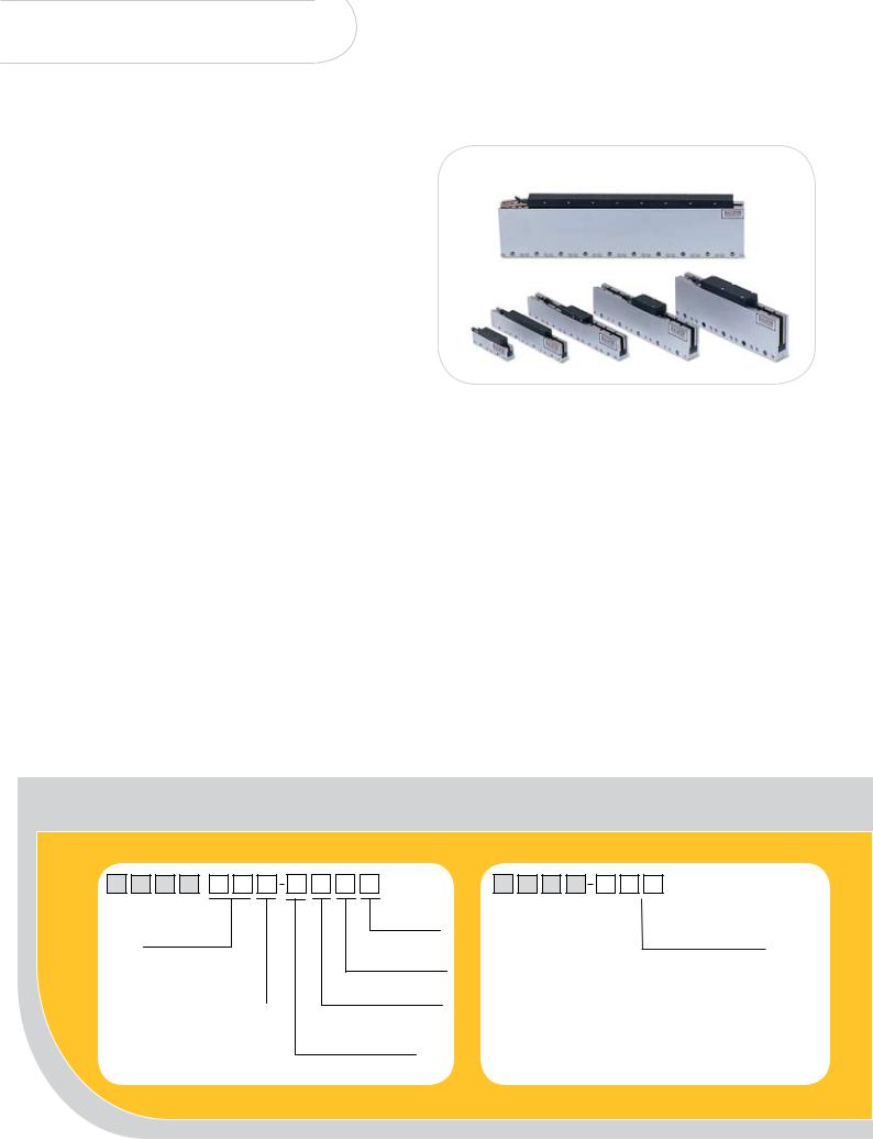
Cog-free Brushless Servo Motors
›› Standard and custom magnetic track lengths
›› Peak forces from 16N [3.6 Lbs] to 2300 N [517 Lbs] ›› High acceleration to 98m/s2 [10g’s]
›› High speeds to 10m/s [400 in/sec] with encoder resolutions
≥1 micron
›› Speeds to 2.5m/s [100 in/sec] with encoder resolutions
≤ 1 micron
›› High accuracy 2.5μm/300m [±0.0001 in/ft] (encoder dependent)
›› High repeatability 1μm [0.00004 in] (encoder dependent) ›› Unlimited stroke length
›› Independent multiple coil operation with overlapping trajectories
›› No metal-to-metal contact, virtually maintenance free ›› Modular magnet tracks
The cog free motor is designed for unlimited stroke servo applications that require smooth operation without magnetic force variation or “cogging”. A large range of motors are available to suit different applications. These motors are supplied in kit form to be integrated into your machine. They are used in closed loop servo systems and provide optimum performance.
For higher continuous forces, air and water cooling options are available.
Baldor’s cog free motors are ideally suited for applications requiring high accuracy (with resolutions down to 0.1µm) and smooth movement.
The motors can be controlled from any of Baldor’s 3 phase brushless drive family, including MicroFlex, FlexDrive-II, Flex+Drive-II and MintDrive-II. The motors are also compatible with the NextMove range of motion controllers for multi-axis position control.
Baldor’s cog free linear motors are nickel plated meeting ROHS compliance.
Baldor provides standard magnetic track lengths to optimize pricing for customers. These standards include: LTCF-C24, LTCF-E24, LTCF-F24; and LTCF-C40, LTCF-E40, LTCF-F40. Other track lengths are available as custom.
››Ordering Information 
Primary (Forcer) |
Secondary (Magnet Track) |
L |
M |
C |
F |
L |
T |
C |
F |
NO. OF POLES
02, 04...18
SIZE CODE mm [inch]
A = 40 [1.6] |
D = 86.4 [3.4] |
B = 53.6 [2.11] |
E = 114.3 [4.5] |
C = 57.2 [2.25] |
F = 152.4 [6.0] |
WINDING
Blank = Standard
P = Parallel
TERMINATION
O = Flying Leads (3m/10 ft. Std.)
COOLING TYPE
C = Convection
A = Air Cooling
W = Water
HALLS
H = Hall E ect Sensors
N = No E ect Sensors
|
|
|
|
|
|
|
|
|
|
|
|
|
|
|
|
CODE FOR LENGTH |
|||
SIZE CODE mm [inch] |
|
|
OF MODULAR TRACK mm [inch] |
||||||
|
A = 40.7 [1.6] |
04 |
= 121.9 [4.8] |
||||||
|
B = 53.6 |
[2.11] |
|
07 |
= 182.9 [7.2] |
||||
* C = 57.2 |
[2.25] |
|
09 |
= 243.8 |
[9.6] |
||||
|
D = 86.4 |
[3.4] |
|
12 |
= 304.8 |
[12] |
|||
* E = 114.3 [4.5] |
* 24 |
= 609.6 |
[24] |
||||||
* F = 152.4 [6.0] |
* 40 |
= 1036 [40.8] |
|||||||
* Indicates standard size and length

Cog-free Brushless Technical Data
››Technical Data
|
Catalog Numbers |
Continuous Force |
Continuous |
Peak Force @ |
Peak |
Back-EMF Constant Kemf |
||||
|
Current @ |
|||||||||
|
|
(1) - (2) - (3) |
Current |
|
10% Duty |
10% Duty |
(ph-ph) |
|||
|
|
|
|
|
|
|
|
|
|
|
|
|
N |
Lbs |
Amps |
N |
|
Lbs |
Amps |
V/m/sec |
V/in/sec |
|
|
|
|
|
|
|
|
|
|
|
|
LMCF02A-HCO |
5.3 |
1.2 |
1.7 |
16 |
|
3.6 |
5.1 |
3.1 |
0.08 |
|
|
|
|
|
|
|
|
|
|
|
|
LMCF02B-HCO |
13.8 |
3.1 |
2.1 |
41.8 |
|
9.4 |
6.3 |
6.7 |
0.17 |
|
|
|
|
|
|
|
|
|
|
|
|
LMCF04B-HCO |
27.8 |
6.2 |
2.1 |
83.3 |
|
18.7 |
6.3 |
13.2 |
0.34 |
|
|
|
|
|
|
|
|
|
|
|
(4) |
LMCF02C-HCO |
29 |
6.5 |
1.9 |
86.8 |
|
19.5 |
5.7 |
15.2 |
0.39 |
|
|
|
|
|
|
|
|
|
|
|
(4) |
LMCF04C-HCO |
58 |
13 |
1.9 |
173 |
|
39 |
5.7 |
30.4 |
0.77 |
|
|
|
|
|
|
|
|
|
|
|
(4) |
LMCF06C-HCO |
87 |
19.5 |
1.9 |
260 |
|
58 |
5.7 |
45.6 |
1.16 |
|
|
|
|
|
|
|
|
|
|
|
(4) |
LMCF08C-HCO |
116 |
26 |
1.9 |
347 |
|
78 |
5.7 |
60.9 |
1.55 |
|
|
|
|
|
|
|
|
|
|
|
|
LMCF02D-HCO |
36.8 |
8.3 |
1.5 |
110 |
|
24 |
4.4 |
24.8 |
0.63 |
|
|
|
|
|
|
|
|
|
|
|
|
LMCF04D-HCO |
73.6 |
16.5 |
1.5 |
220 |
|
49 |
4.4 |
49.6 |
1.26 |
|
|
|
|
|
|
|
|
|
|
|
|
LMCF06D-HCO |
110 |
24.8 |
1.5 |
330 |
|
74 |
4.4 |
74.4 |
1.89 |
|
|
|
|
|
|
|
|
|
|
|
|
LMCF08D-HCO |
147 |
33 |
1.5 |
440 |
|
99 |
4.4 |
99.3 |
2.52 |
|
|
|
|
|
|
|
|
|
|
|
|
LMCF10D-HCO |
184 |
41.3 |
3.0 |
550 |
|
123 |
8.9 |
61.8 |
1.57 |
|
|
|
|
|
|
|
|
|
|
|
|
LMCF12D-HCO |
220 |
49.6 |
3.0 |
660 |
|
148 |
8.9 |
74.2 |
1.88 |
|
|
|
|
|
|
|
|
|
|
|
(4) |
LMCF04E-HCO |
124 |
28 |
1.6 |
372 |
|
84 |
4.7 |
79.9 |
2.03 |
|
|
|
|
|
|
|
|
|
|
|
(4) |
LMCF06E-HCO |
185 |
42 |
3.1 |
556 |
|
125 |
9.2 |
59.7 |
1.52 |
|
|
|
|
|
|
|
|
|
|
|
(4) |
LMCF08E-HCO |
251 |
56 |
3.1 |
753 |
|
169 |
9.2 |
82.0 |
2.08 |
|
|
|
|
|
|
|
|
|
|
|
(4) |
LMCF10E-HCO |
314 |
70 |
3.1 |
942 |
|
212 |
9.2 |
102.5 |
2.60 |
|
|
|
|
|
|
|
|
|
|
|
(4) |
LMCF12E-HCO |
377 |
85 |
3.1 |
1132 |
|
254 |
9.2 |
123.0 |
3.12 |
|
|
|
|
|
|
|
|
|
|
|
(4) |
LMCF14E-HCO |
440 |
99 |
3.1 |
1318 |
|
294 |
9.2 |
143.5 |
3.64 |
|
|
|
|
|
|
|
|
|
|
|
(4) |
LMCF04F-HCO |
191 |
43 |
2.6 |
578 |
|
130 |
7.8 |
74.4 |
1.89 |
|
|
|
|
|
|
|
|
|
|
|
(4) |
LMCF08F-HCO |
387 |
87 |
2.6 |
1152 |
|
256 |
7.8 |
148.4 |
3.78 |
|
|
|
|
|
|
|
|
|
|
|
(4) |
LMCF12F-HCO |
578 |
130 |
3.9 |
1726 |
|
338 |
11.6 |
148.4 |
3.77 |
|
|
|
|
|
|
|
|
|
|
|
(4) |
LMCF16F-HCO |
771 |
173 |
5.2 |
2300 |
|
517 |
15.6 |
148.0 |
3.76 |
|
|
|
|
|
|
|
|
|
|
|
Notes: All specifications are for reference only.
Technical data at 750C rise over 250C ambient.
(1) Addition of 254 x 254 x 25.4 mm [10 x 10 x 1 in] aluminum heat sink increases continuous force capability by 20% (along with 20% more current). (2) Addition of forced air cooling increases continuous force 12% (and 12% more current).
(3) Liquid cooling option increases continuous forces by 25% and power dissipation by 50%. Available only on motors with D, E and F “size codes.” (4) Standard Motor
Linear Motors and Stages
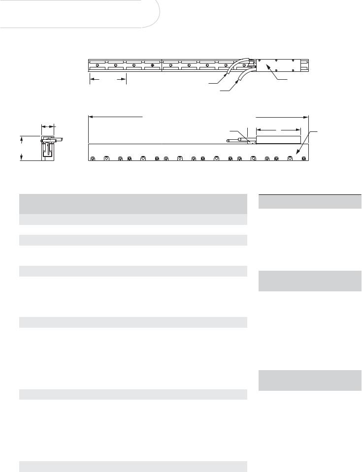
Cog-free Brushless Motors Dimensions
60.9mm |
|
|
|
COIL ASSEMBLY |
(2.4”) |
OPTIONAL HALL LEADS |
|
|
|
|
|
(FORCER) |
||
|
|
|
|
|
|
MOTOR LEADS |
|
|
|
|
D = 122mm (4.80”) + N * 61mm (2.4”) (N = 0,1,2...) |
|
|
|
W |
or multiples of 30.5mm (1.2") for non-standard tracks |
|
|
|
|
(OPTIONAL |
0.65” |
A |
TRACK ASSEMBLY |
|
Max |
|
||
|
HALL MODULE) |
|
|
|
H1
Track assemblies can be stacked for additional stroke lengths.
Forcer/Primary (Coil Assembly) - LMCF
Catalog Number |
|
A |
|
W |
|
H1 |
Weight |
||||
|
|
|
|
|
|
|
|
|
|
|
|
|
mm |
|
in |
mm |
|
in |
mm |
|
in |
Kg |
Lbs |
|
|
|
|
|
|
|
|
|
|
|
|
Size A |
|
|
|
|
|
|
|
|
|
|
|
|
|
|
|
|
|
|
|
|
|
||
LMCFO2A-HCO |
73.7 |
|
2.90 |
20.8 |
|
0.82 |
40.64 |
|
1.60 |
0.08 |
0.17 |
|
|
|
|
|
|
|
|
|
|
|
|
Size B |
|
|
|
|
|
|
|
|
|
|
|
|
|
|
|
|
|
|
|
|
|
||
LMCFO2B-HCO |
73.7 |
|
2.90 |
20.83 |
|
0.82 |
53.59 |
|
2.11 |
0.11 |
0.25 |
LMCFO4B-HCO |
134.6 |
|
5.30 |
20.83 |
|
0.82 |
53.59 |
|
2.11 |
0.22 |
0.49 |
|
|
|
|
|
|
|
|
|
|
|
|
Size C |
|
|
|
|
|
|
|
|
|
|
|
|
|
|
|
|
|
|
|
|
|||
LMCFO2C-HCO |
73.7 |
|
2.90 |
30.48 |
|
1.20 |
57.15 |
|
2.25 |
0.18 |
0.39 |
|
|
|
|
|
|
|
|
|
|
|
|
LMCFO4C-HCO |
134.6 |
|
5.30 |
30.48 |
|
1.20 |
57.15 |
|
2.25 |
0.32 |
0.70 |
|
|
|
|
|
|
|
|
|
|
|
|
LMCFO6C-HCO |
195.6 |
|
7.70 |
30.48 |
|
1.20 |
57.15 |
|
2.25 |
0.57 |
1.25 |
|
|
|
|
|
|
|
|
|
|
|
|
LMCFO8C-HCO |
256.5 |
|
10.10 |
30.48 |
|
1.20 |
57.15 |
|
2.25 |
0.75 |
1.64 |
|
|
|
|
|
|
|
|
|
|
|
|
Size D |
|
|
|
|
|
|
|
|
|
|
|
|
|
|
|
|
|
|
|
|
|||
LMCFO2D-HCO |
73.7 |
|
2.90 |
34.29 |
|
1.35 |
86.31 |
|
3.40 |
0.35 |
0.76 |
|
|
|
|
|
|
|
|
|
|
|
|
LMCFO4D-HCO |
134.6 |
|
5.30 |
34.29 |
|
1.35 |
86.31 |
|
3.40 |
0.6 |
1.4 |
|
|
|
|
|
|
|
|
|
|
|
|
LMCFO6D-HCO |
195.6 |
|
7.70 |
34.29 |
|
1.35 |
86.31 |
|
3.40 |
0.9 |
2.0 |
|
|
|
|
|
|
|
|
|
|
|
|
LMCFO8D-HCO |
256.5 |
|
10.10 |
34.29 |
|
1.35 |
86.31 |
|
3.40 |
1.2 |
2.6 |
|
|
|
|
|
|
|
|
|
|
|
|
LMCF10D-HCO |
317.5 |
|
12.50 |
34.29 |
|
1.35 |
86.31 |
|
3.40 |
1.5 |
3.2 |
|
|
|
|
|
|
|
|
|
|
|
|
LMCF12D-HCO |
378.5 |
|
14.90 |
34.29 |
|
1.35 |
86.31 |
|
3.40 |
1.8 |
3.9 |
|
|
|
|
|
|
|
|
|
|
|
|
Size E |
|
|
|
|
|
|
|
|
|
|
|
|
|
|
|
|
|
|
|
|
|||
LMCFO4E-HCO |
134.6 |
|
5.30 |
39.37 |
|
1.55 |
114.3 |
|
4.50 |
0.77 |
1.7 |
|
|
|
|
|
|
|
|
|
|
|
|
LMCFO6E-HCO |
195.6 |
|
7.70 |
39.37 |
|
1.55 |
114.3 |
|
4.50 |
1.1 |
2.5 |
|
|
|
|
|
|
|
|
|
|
|
|
LMCFO8E-HCO |
256.5 |
|
10.10 |
39.37 |
|
1.55 |
114.3 |
|
4.50 |
1.5 |
3.2 |
|
|
|
|
|
|
|
|
|
|
|
|
LMCF10E-HCO |
317.5 |
|
12.50 |
39.37 |
|
1.55 |
114.3 |
|
4.50 |
1.8 |
4.0 |
|
|
|
|
|
|
|
|
|
|
|
|
LMCF12E-HCO |
378.5 |
|
14.90 |
39.37 |
|
1.55 |
114.3 |
|
4.50 |
2.2 |
4.8 |
|
|
|
|
|
|
|
|
|
|
|
|
LMCF14E-HCO |
439.4 |
|
17.30 |
39.37 |
|
1.55 |
114.3 |
|
4.50 |
2.5 |
5.6 |
|
|
|
|
|
|
|
|
|
|
|
|
Size F |
|
|
|
|
|
|
|
|
|
|
|
|
|
|
|
|
|
|
|
|
|||
LMCFO4F-HCO |
156.2 |
|
5.30 |
44.0 |
|
1.73 |
152.4 |
|
6.00 |
1.65 |
3.6 |
|
|
|
|
|
|
|
|
|
|
|
|
LMCFO8F-HCO |
256.5 |
|
10.10 |
44.0 |
|
1.73 |
152.4 |
|
6.00 |
3.1 |
6.8 |
|
|
|
|
|
|
|
|
|
|
|
|
LMCF12F-HCO |
378.5 |
|
14.90 |
44.0 |
|
1.73 |
152.4 |
|
6.00 |
4.5 |
9.9 |
|
|
|
|
|
|
|
|
|
|
|
|
Secondary (Track) - LTCF
Standard cog-free tracks include:
610 mm (24inch) |
1036 mm (40.8 inch) |
|
|
|
|
LTCF-C24 |
LTCF-C40 |
|
|
|
|
LTCF-E24 |
LTCF-E40 |
|
|
|
|
LTCF-F24 |
LTCF-F40 |
|
|
|
|
Other track lengths are available as custom |
||
|
|
|
Catalog Number |
|
D |
|
|
|
|
mm |
in |
|
|
|
LTCF-X04 |
122 |
4.8 |
|
|
|
LTCF-X07 |
183 |
7.2 |
|
|
|
LTCF-X09 |
244 |
9.6 |
|
|
|
LTCF-X12 |
305 |
12.0 |
|
|
|
LTCF-X24 |
610 |
24.0 |
|
|
|
LTCF-X40 |
1036 |
40.8 |
|
|
|
|
|
|
Catalog Number |
Weight |
|
|
|
|
|
Kg/m |
Lb/in |
|
|
|
LTCF-AXX |
3.6 |
0.20 |
|
|
|
LTCF-BXX |
5.5 |
0.31 |
|
|
|
LTCF-CXX |
8.1 |
0.45 |
|
|
|
LTCF-DXX |
11.6 |
0.65 |
|
|
|
LTCF-EXX |
17.2 |
0.96 |
|
|
|
LTCF-FXX |
34 |
1.90 |
|
|
|
NOTE: Min track length recommended = “A” dimension + 0.65 inch [1.65mm] + stroke [min 3 inch (76.2mm)]