

Constr_materials
.pdfTable 9.6 Designation, Compositions, Mechanical Properties, and Typical Applications for Several Stainless Steels
AISI |
Composi- |
Condi- |
Mechanical Properties |
Typical |
|||
Tensile |
Yield |
|
|||||
Num- |
tion (% |
Ductility |
|||||
b |
Strength |
Strength |
Applications |
||||
ber |
wt.)a |
tion |
[%EL ] |
||||
|
|
|
[MPa] |
[MPa] |
|
|
|
|
|
|
|
|
|
Automotive |
|
|
0.08 C, 11.0 |
|
|
|
|
exhaust |
|
409 |
Cr, 1.0 Mn, |
Annealed |
380 |
205 |
20 |
components, |
|
0.50 Ni, |
tanks for |
||||||
|
|
|
|
|
|||
|
0.75 Ti |
|
|
|
|
agricultural |
|
|
|
|
|
|
|
sprays |
|
|
|
|
|
|
|
Valves, glass |
|
446 |
0.20 C, 25 |
Annealed |
515 |
275 |
20 |
molds, |
|
Cr, 1.5 Mn |
combustion |
||||||
|
|
|
|
|
|||
|
|
|
|
|
|
chambers |
|
|
|
|
|
|
|
Chemical and |
|
|
0.08 C, 19 |
|
|
|
|
food |
|
|
|
|
|
|
processing |
||
304 |
Cr, 9 Ni, |
Annealed |
515 |
205 |
40 |
||
equipment, |
|||||||
|
2.0 Mn |
|
|
|
|
||
|
|
|
|
|
cryogenic |
||
|
|
|
|
|
|
||
|
|
|
|
|
|
vessels |
|
|
0.03 C, 17 |
|
|
|
|
|
|
316L |
Cr, 12 Ni, |
Annealed |
485 |
170 |
40 |
Welding |
|
2.5 Mo, 2.0 |
constructions |
||||||
|
|
|
|
|
|||
|
Mn |
|
|
|
|
|
|
|
0.15 C, 12.5 |
Annealed |
485 |
275 |
20 |
Rifle barrels, |
|
410 |
Cr, 1.0 Mn |
|
|
|
|
cutlery, jet |
|
Q & T |
825 |
620 |
12 |
||||
|
engine parts |
||||||
|
|
||||||
|
0.70 C, 17 |
Annealed |
725 |
415 |
20 |
Cutlery, |
|
440A |
Cr, 0.75 |
|
|
|
|
bearings, |
|
|
|
|
|
||||
|
Mo, 1.0 Mn |
Q & T |
1790 |
1650 |
5 |
surgical tools |
|
|
|
|
|
|
|
|
|
|
0.09 C, 17 |
Precipi- |
|
|
|
Springs, |
|
17- |
Cr, 7 Ni, |
|
|
|
knives, |
||
tation |
1450 |
1310 |
1-6 |
||||
7PH |
1.0 Al, 1.0 |
pressure |
|||||
hardened |
|
|
|
||||
|
Mn |
|
|
|
vessels |
||
|
|
|
|
|
|||
aThe balance of the composition is iron.
bQ & T denotes quenched and tempered.
81
Created with novaPDF Printer (www.novaPDF.com). Please register to remove this message.
9.4. CAST IRONS
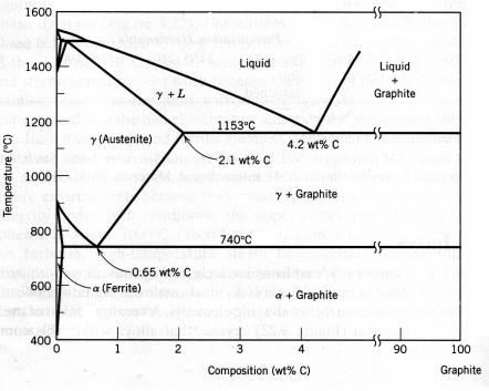
True equilibrium diagram for iron and carbon
Generally, cast irons are a class of ferrous alloys with carbon contents above 2.14 % wt.; in practice, however, the most part of cast irons contain 3.0 to 4.5 % wt. C and, in addition, other alloying elements. A reexamination of the iron–iron carbide phase diagram reveals that alloys within this composition range become completely liquid at temperatures approximately 1150 to 1300 ?C, which is considerably lower as compared to steels. Thus, they are easily melted and amenable to casting. Furthermore, some cast irons are very brittle and casting is the most convenient fabrication technique.
Cementite (Fe3C) is a metastable compound, and under some circumstances it can be made to dissociate or decompose to form α ferrite and graphite according to the reaction
Fe3C → 3Fe (α) + C (graphite). (9.1) Thus, the true equilibrium diagram for iron and carbon is not that presented in Figure 9.4 on page 69, but rather as shown in Figure 9.9. The two diagrams are virtually identical on the iron-rich side; however, Figure 9.9 extends to 100 % wt. carbon such that graphite is the carbon-rich phase, instead
of cementite at 6.7 % wt. C.
Figure 9.9 The true equilibrium iron–carbon phase diagram with graphite
82
Created with novaPDF Printer (www.novaPDF.com). Please register to remove this message.

This tendency to form graphite is regulated by the composition and rate of cooling. Graphite formation is promoted by the presence of silicon in concentrations greater than about 1 % wt. Also, slower cooling rates during solidification favor graphitization (the formation of graphite). For most cast irons, the carbon exists as graphite, and both microstructure and mechanical behavior depend on composition and heat treatment. The most common cast iron types are gray, nodular, white and malleable.
Gray irons
The carbon and silicon contents of gray cast irons vary between 2.5 and 4.0 % wt. and 1.0 and 3.0 % wt., respectively. For most of these cast irons, the graphite exists in the form of flakes (similar to corn flakes), which are normally surrounded by the α ferrite or pearlite matrix; the microstructure of a typical gray iron is shown in Figure 9.11, a. Because of these graphite flakes, a fracture surface has a gray appearance, hence its name.
Mechanically, gray iron is comparatively weak and brittle in tension as a consequence of its microstructure; the tips of the graphite flakes are sharp and pointed, and may serve as points of stress concentration when an external tensile stress is applied. Both strength and ductility are much higher under compressive loads. Typical mechanical properties and compositions of several of the common gray cast irons are listed in Table 9.7. Gray irons do have some desirable characteristics and, in fact, are utilized extensively. They are very effective in damping vibrational energy; this is represented in Figure 9.10, which compares the relative damping capacities of steel and gray iron. Base structures for machines and heavy equipment that are exposed to vibrations are frequently constructed of this material.
In addition, gray irons exhibit a high fluidity at casting temperature, which permits casting pieces having intricate shapes; also, casting shrinkage is low. Finally, and perhaps most important, gray cast irons are among the least expensive of all metallic materials.
Figure 9.10 Damping capacities of steel (a) and gray cast iron (b)
83
Created with novaPDF Printer (www.novaPDF.com). Please register to remove this message.

Table 9.7 Designations, Minimum Mechanical Properties, Approximate Compositions, and Typical Applications for Various Gray, Nodular, and Malleable Cast Irons
|
UNS |
Composi- |
Matrix |
|
Mechanical Properties |
|
||
Grade |
|
Tensile |
Yield |
|
Typical Applications |
|||
Num- |
|
Ductility |
||||||
tion (% wt.)a |
Structure |
|
Strength |
Strength |
||||
|
ber |
|
|
|
[MPa] |
[MPa] |
[%EL] |
|
|
|
|
|
|
|
|
||
|
|
|
|
|
Gray Iron |
|
|
|
|
|
3.4-3.7 C, |
Ferrite + |
|
|
– |
– |
Miscellaneous soft iron castings in |
SAE G1800 |
F10004 |
2.55 Si, |
|
124 |
which strength is not a primary |
|||
Pearlite |
|
|||||||
|
|
0.7 Mn |
|
|
|
|
consideration |
|
|
|
|
|
|
|
|
||
|
|
3.2-3.5 C, |
Ferrite + |
|
|
– |
– |
Small cylinder blocks, cylinder heads, |
SAE G2500 |
F10005 |
2.20 Si, |
|
173 |
||||
Pearlite |
|
pistons, clutch plates, transmission cases |
||||||
|
|
0.8 Mn |
|
|
|
|
||
|
|
|
|
|
|
|
|
|
SAE G4000 |
F10008 |
3.0-3.3 C, |
Pearlite |
|
276 |
– |
– |
Diesel engine castings, liners, cylinders, |
2.0 Si, 0.8 Mn |
|
and pistons |
||||||
|
|
|
|
|
|
|
||
|
|
|
|
Ductile (Nodular) Iron |
|
|
||
ASTM A536 |
F32800 |
3.5-3.8 C, |
Ferrite |
|
414 |
276 |
18 |
Pressure-containing parts such as valve |
60-40-18 |
|
and pump bodies |
||||||
|
2.0-2.8 Si, |
|
|
|
|
|
||
|
|
|
|
|
|
|
High-strength gears and machine |
|
100-70-03 |
F34800 |
0.05 Mg, |
Pearlite |
|
689 |
483 |
3 |
|
|
components |
|||||||
|
|
<0.20 Ni, |
|
|
|
|
|
|
|
|
Tempered |
|
|
|
|
|
|
120-90-02 |
F36200 |
<0.20 Mo |
|
827 |
621 |
2 |
Pinions, gears, rollers, sliders |
|
martensite |
|
|||||||
|
|
|
|
|
|
|
|
|
|
|
|
|
|
Malleable Iron |
|
|
|
|
|
2.3-2.7 C, |
|
|
|
|
|
|
32510 |
F22200 |
1.0-1.75 Si, |
Ferrite |
345 |
224 |
10 |
|
|
|
|
<0.55 Mn |
|
|
|
|
|
General engineering service at normal |
|
– |
2.4-2.7 C, |
Ferrite + |
|
|
|
|
and elevated temperatures |
45006 |
1.25-1.55 Si, |
448 |
310 |
6 |
|
|||
Pearlite |
|
|||||||
|
|
<0.55 Mn |
|
|
|
|
|
|
|
|
|
|
|
|
|
|
|
a The balance of the composition is iron.
84
Created with novaPDF Printer (www.novaPDF.com). Please register to remove this message.

a |
b |
|
|
c |
d |
Figure 9.11 Photomicrograph of various cast irons:
a – gray iron, b – nodular (ductile) iron, c – white iron, d – malleable iron
Gray irons having microstructures different from that shown in Figure 9.11, a may be generated by adjustment of composition and/or by using an appropriate treatment. For example, reducing the silicon content or increasing the cooling rate may prevent the complete decomposition of cementite to form graphite (Equation 9.1). Under these circumstances the microstructure consists of graphite flakes embedded in a pearlite matrix. Figure 9.12 on page 86 compares schematically the several cast iron microstructures obtained by varying the composition and heat treatment.
Ductile (or nodular) iron
Adding a small amount of magnesium or cerium to the gray irons before casting produces a distinctly different microstructure and a set of mechanical properties. Graphite still forms, but as nodules or spherelike particles instead of flakes. The resulting alloy is called nodular or ductile
85
Created with novaPDF Printer (www.novaPDF.com). Please register to remove this message.

iron, and a typical microstructure is shown in Figure 9.11, b. The matrix phase surrounding these particles is either pearlite or ferrite, depending on heat treatment (Fig. 9.12); it is normally pearlite for an as-cast piece. However, a heat treatment for several hours at about 700 ?C will yield a ferrite matrix as shown in this photomicrograph. Castings are stronger and much more ductile than gray iron, as a comparison of their mechanical properties in Table 9.7 shows. In fact, ductile iron has mechanical characteristics approaching to those of steel. For example, ferritic ductile irons have tensile strengths ranging between 380 and 480 MPa, and ductilities (as percent elongation) 10 to 20 %. Typical applications for this material include valves, pump bodies, crankshafts, gears, and other automotive and machine components.
Figure 9.12 Composition ranges and microstrutures of various cast irons
86
Created with novaPDF Printer (www.novaPDF.com). Please register to remove this message.
White iron and malleable iron
For low-silicon cast irons (containing less than 1.0 % wt. Si) and rapid cooling rates, most of the carbon exists as cementite instead of graphite, as indicated in Figure 9.12. A fracture surface of this alloy has a white appearance, and thus it is termed white cast iron. An optical photomicrograph showing the microstructure of white iron is presented in Figure 9.11, c. Thick sections may have only a surface layer of white iron that was “chilled” during the casting process; gray iron is formed at interior regions, which cool more slowly. As a consequence of large amounts of the cementite phase, white iron is extremely hard but also very brittle, to the point of being virtually unmachinable. Its use is limited to applications that necessitate a very hard and wear-resistant surface, and without a high degree of ductility – for example, as rollers in rolling mills. Generally, white iron is used as an intermediary production of yet another cast iron, malleable iron.
Heating white iron at temperatures between 800 and 900 ?C for a prolonged time period and in a neutral atmosphere (to prevent oxidation) causes a decomposition of the cementite, forming graphite, which exists in the form of clusters or rosettes surrounded by a ferrite or pearlite matrix, depending on cooling rate, as indicated in Figure 9.12. A photomicrograph of a ferritic malleable iron is presented in Figure 9.11, d. The microstructure is similar to that for nodular iron, which accounts for relatively high strength and appreciate ductility or malleability.
Representative applications include connecting rods, transmission gears, and differential cases for the automotive industry; also flanges, pipe fittings, and valve parts for rail road, marine and other heavy-duty services.
Questions and problems
19.List the components and phases in iron–carbon system.
20.Analyze phase diagram iron–iron carbide. Show and describe liquidus and solidus, lines of limited solubility of carbon in Fe and Fe, fields of solid solutions ferrite and austenite, temperature and concentration for eutectic and eutectoid.
21.Explain phase transformations in iron–carbon alloys.
22.What is the point in dividing iron-carbon alloys into steels and cast irons?
23.Steel classification by the structure.
24.What is the distinction between hypoeutectoid and hypereutectoid steels?
25.What are plain carbon steels?
26.Explain carbon influence upon steel properties.
27.What are the useful and harmful impurities in steel and what is their influence upon steel properties?
28.List the four classifications of steels. For each, briefly describe the properties and typical applications.
87
Created with novaPDF Printer (www.novaPDF.com). Please register to remove this message.
29.What is the function of alloying elements in tool steels?
30.Give the definitions to all types of cast irons.
31.On the basis of microstructure, briefly explain why gray iron is brittle and weak in tension.
32.Compare gray and malleable cast iron with respect to microstructure and mechanical characteristics.
33.Describe the treatment necessary to produce each of four types of cast irons.
34.What is the main performance for white cast iron?
88
Created with novaPDF Printer (www.novaPDF.com). Please register to remove this message.
10. HEAT TREATMENT OF STEEL
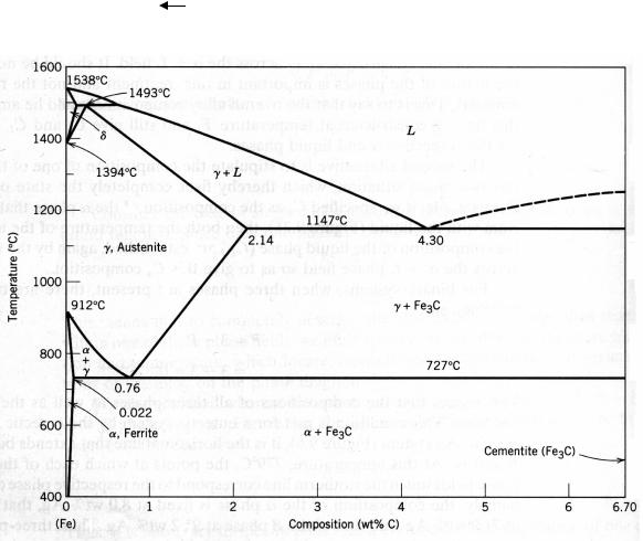
The iron–carbon alloys that contain between 0.02 and 2.14 % wt. C are classified as steels. The development of a set of desirable mechanical characteristics for steels results from a phase transformation, which is achieved by a heat treatment. For example, the tensile strength of an iron– carbon alloy of eutectoid composition (0.8 % wt. C) can be varied between approximately 700 MPa and 2000 MPa depending on the heat treatment employed.
The iron–carbon phase diagram presented in Figure 10.1 provides us with valuable information about the development of microstructure of the alloys. The eutectoid phase changes are very important, being fundamental to the heat treatment of steels. This eutectoid reaction may be represented by
cooling
γ(0.8 % wt. C) α(0.02 % wt. C) + Fe3C (6.7 % wt. C). (10.1)
heating
Figure 10.1 The iron–iron carbide phase diagram
It means that, upon cooling, the solid γ phase, or austenite, is transformed to α iron, called ferrite, and cementite. Upon heating, the processes develop in opposite order.
89
Created with novaPDF Printer (www.novaPDF.com). Please register to remove this message.

10.1. WHAT IS HEAT TREATMENT?
Heat treatment is a set of operations of heating and cooling used for changing structure and properties of an alloy in the necessary direction.
There are two types of thermal treatment: strengthening thermal processing, which raises hardness, strength and wear resistance, and softening treatment, which raises plastic properties and toughness, but reduces hardness and resistance to deformation and rupture.
Both variants of thermal processing are widely applied to steel products.
It is possible to present any operation of thermal processing graphically in the form of a curve in co-ordinates “temperature – time”, including periods of heating, holding and cooling. The main parameters, defining result of thermal processing, are heating temperature th, holding time h and cooling rate vc (Fig. 10.2).
Thermal processing of steel is based on the phase transformations which occur upon
heating above critical temperatures and cooling with various rates.
10.2. PHASE TRANSFORMATION IN STEELS UPON HEATING
It is accepted to designate the temperatures of transformations, or critical points of steel at heating, by following manner (Fig. 10.3):
|
he beginning of ferrite – austenite transformation (Fe Fe ) |
is marked as Ac1 (these points are located on line PSK); |
|
|
The end of ferrite – austenite transformation (Fe Fe ) is |
marked as Ac3 (these points lie on line GS); |
|
|
The end of dissolution of cementite in austenite is marked as |
Accm (points are on line SE).
Points A2 concern to magnetic transformation, which we do not consider
here.
It is necessary to note that points Ac3 and Accm are specific to each steel, and point Ac1 is the same for all carbon steels: 727 °С.
Let's consider the transformations that occur upon heating of the eutectoid steel (Fig. 10.3, composition 1-1).
90
Created with novaPDF Printer (www.novaPDF.com). Please register to remove this message.