

Constr_materials
.pdfThe poligonized structure is steady up to fusion temperature. This process is typical, for example, for iron, aluminum, molybdenum.
а |
b |
Figure 7.2 Photomicrograph of high-speed steel, non-deformed (а) and after small deformation degree followed by polygonization (b). 1200
7.2. RECRYSTALLIZATION
Recrystallization is the formation of a new set of strain-free equiaxial grains that have low dislocation densities. The driving force to produce this new grain structure is the difference in internal energy between the strained and unstrained material. The new grains are formed as very small nuclei and grow until they completely replace the parent material.
New grains, more perfect than strained ones, appear and grow upon heating above the recrystallization temperature Tr. This temperature is a fraction of the melting temperature Tm and can be defined by the formula:
Tr = a Tm.
The factor a depends on the impurity concentration in metal: for commercially pure metals a = 0.4;
for chemically pure metals a = 0.1-0.2; for alloys a = 0.6-0.7.
Recrystallization temperature of commercially pure copper is 270 ?С, iron –
450 ?С, aluminum – 100 ?С.
When all the deformed grains are replaced with new, equiaxial ones, it means that primary recrystallization has come to the end. The new unstrained grains have very low density of dislocations (105-106 cm-2) in comparison to the deformed structure. When primary recrystallization terminated, new grains simultaneously have already grown up and their sizes are now almost the same. This process is called collective recrystallization; it influences structure and properties of metal favourably. But then secondary recrystallization can begin: growth of some grains at the expense of others.
51
Created with novaPDF Printer (www.novaPDF.com). Please register to remove this message.

Thus the total surface of grains decreases, i. e. motive power of the process is the tendency to the minimum surface energy. The structure consisting of grains various in sizes leads to simultaneous drop in strength and plasticity. It is undesirable process.
Several stages in the recrystallization process are represented in Figure 7.3. Thus, recrystallization of cold-worked metals may be used to refine the grain structure.
Figure 7.3 Changes in microstructure upon the recrystallization and grain growth
Recrystallization removes strain hardening completely, the metal gets equilibrium structure with the least number of crystalline defects. Properties of metal after recrystallization are close to ones of annealed metal.
The changes in mechanical characteristics of metal after recrystallization processes are shown in Figure 7.4.
Figure 7.4 Influence of the recrystallization and grain growth on tensile strength and percent elongation
7.3. HOT AND COLD PLASTIC DEFORMATION
Deformation of metal at the temperatures below the recrystallization temperature is called a cold plastic deformation. During the cold deformation metal becomes harder and acquires high strength and hardness. Examples of
52
Created with novaPDF Printer (www.novaPDF.com). Please register to remove this message.
cold plastic deformation application: wire drawing accompanied by hardening, thread rolling, cold sheet-metal die forging.
Deformation of metals upon heating above recrystallization temperature is called a hot plastic deformation. Metal after the hot deformation remains ductile and is suitable for the further processing by pressure or cutting. The most part of metals and alloys is exposed to hot plastic deformation processing at rolling and forge shops of the metallurgical enterprises as well as then at machine-building plants.
Questions and problems
1.What is work hardening?
2.Change of structure and properties of metal upon plastic deformation.
3.Change of structure and properties of the deformed metal upon heating.
4.Recovery and polygonization.
5.Recrystallization. Recrystallization temperature. Primary, collective and secondary recrystallization.
6.Hot and cold plastic deformation.
53
Created with novaPDF Printer (www.novaPDF.com). Please register to remove this message.
8. ALLOYS
Application of pure metals is limited. Modern engineering is based on alloys which have much wider spectrum of mechanical and service properties. Alloys are the metal materials consisting of two or more elements including non-metals. It is accepted to name substances forming an alloy as components. Components can be simple (Fe, Cu) and complex (Fe3C, CuAl2). Alloy components interact and form various phases. A phase is a part of the alloy having homogeneous structure and properties, and separated by a well-defined boundary from other parts.
The term “alloy” means that originally these materials were obtained in practice by melting and mixing the components in a liquid state with the subsequent crystallisation. Today there are many other ways too:
powder metallurgy (pressing of powders, then sintering them under high temperatures),
diffusion saturation of the surface of one component by another one,
electrolysis of melt,
crystallisation of vapours in vacuum.
Nevertheless, the term remained. The components which form an alloy, can react differently. A manner of interaction affects the structure and properties of an alloy.
8.1. INTERACTION OF COMPONENTS IN ALLOYS
In the fused condition the majority of metals are dissolved in each other without any limits thus forming a liquid solution. Upon crystallisation they can form similar structure – a solid solution of one component in a lattice of another. Sometimes components enter into chemical interaction and form a chemical compound. Sometimes there is no interaction between components in a solid, and then they crystallise separately, each component forms its own crystallites; in this case alloy represents a mechanical mixture of crystals of initial components.
Let's consider all these cases in more details.
1) Solid solutions is formed when atoms of one component can penetrate into a crystal lattice of another component.
The component which has the highest content and retains its lattice, is called a solvent. The component of lower content takes any suitable positions in a lattice of a solvent and is called a dissolved substance.
Solid solutions can be formed in two ways:
1) Substitutional solid solutions forms when atoms of one component replace atoms of another component in its lattice (see Figure 8.1).
54
Created with novaPDF Printer (www.novaPDF.com). Please register to remove this message.

Here component A is a solvent, and component B is a dissolved substance.
If nuclear radii of two metals are close (a difference in the sizes of atoms should not exceed 15 %), they are usually dissolved in each other. Unlimited solubility is possible for metals when atoms of component B replace atoms of component A in any
proportion, from 0 to 100 %. For this purpose, except the close size of nuclear radiuses, they should have one type of a lattice and an identical structure of valence electron shells. For example, Cu and Ni, Fe and Cr give unlimited solubility.
Much more often a limited solubility is observed when replacement of atoms of solvent by atoms of the dissolved component occurs up to any certain concentration named a
limit of solubility. For example, zinc or tin are dissolved in copper in this way. The limit of solubility of zinc in copper is 39 %.
Interstitial solid solutions arise, if atoms of one component (B) occupy pores in crystalline lattice of other component (A).
Nonmetals with the small sizes of atoms are dissolved in metals as shown in Figure 8.2. Interstitial solid solutions are always limited as the quantity of pores in a lattice is limited. Examples of interstitial solid solutions: carbon in iron, silicon in aluminum.
Under a microscope solid solutions look like pure metals: only boundaries of grains are visible (Fig. 8.3). Solid solution is a single phase, therefore X-ray analysis shows only a
metal-solvent lattice, but its parameters are bigger or smaller than of pure metal ones, because of the distortions caused by dissolved substance atoms.
Properties of the alloys representing solid solutions may differ strongly from properties of initial components. Solid solutions are a basis of the majority of modern industrial alloys because they give the greatest possibilities for getting necessary service
55
Created with novaPDF Printer (www.novaPDF.com). Please register to remove this message.

characteristics.
Solid solutions are designated by the Greek letters: , , , , or A (B), where A is a solvent, B is a solute component.
2) Mechanical mixture of crystals arises, if components cannot be dissolved in each other and do not enter chemical reaction.
Such alloys represent a mixture of initial components crystals grown together. Under microscope magnification, grains of two different kinds are visible: grains A and grains B (Fig. 8.4). It is two-phase structure, therefore X-ray analysis shows two types of lattices:
metal A and metal B.
Properties of an alloy linearly depend on quantity of crystals of that and other component; values of mechanical and physical characteristics are intermediate between properties of pure initial substances. Therefore possibilities of a choice of an alloy with the necessary properties are limited.
The mechanical mix is designated as the sum of two components: A + B.
3) Chemical compound arises, if components can enter chemical reaction with each other and form a stable complex substance with a strictly certain atomic concentration ratio between the components.
It is possible to express a chemical compound concentration by simple formula AmBn, where m and n – natural numbers. Crystalline structure of chemical compound (fluorite) is shown in Figure 8.5.
Chemical compounds are formed by components of different crystal lattices or different structures of valence electron shells.
Example: copper and aluminum have identical type of a crystal lattice (FCC), but a different structure of external electron shells. They form chemical compound CuAl2 with its own crystal lattice (see Fig. 11.3).
Such compounds are called intermetallic. Their crystal lattice, the melting temperature, all physical, chemical and mechanical properties sharply differ from properties of initial components. As a rule, intermetallic compounds have less compact and more complex crystalline lattices than metals. Therefore they are harder and stronger than parent metals, but they have low plasticity.
Alloys may include compounds of
56
Created with novaPDF Printer (www.novaPDF.com). Please register to remove this message.

metals with nonmetals: carbides MexCy, nitrides MexNy, etc.
Chemical compounds may serve for reinforcing the alloys but alloys consisting of a chemical compound only are applied rarely. In this case the chemical compound becomes an alloy
component since it interacts with pure metals. Under a microscope chemical
compounds usually look like small particles inside the grains of pure metal or solid solution (Fig. 8.6). The X-ray analysis, of course, shows new type of a lattice along with the matrix.
So, the components which formed a new material such an alloy are indiscernible with
naked eyes, but various methods of the analysis allow both finding out them and defining their amount (Table 8.1).
Table 8.1 Phase Analysis of Alloys
Type of Alloy |
|
Analysis technique show: |
|
||
Metallography |
|
X-ray analysis |
|
Chemical analysis |
|
|
|
|
|||
Solid solution |
1 kind of crystals: |
|
1 lattice: A; parametre |
|
2 elements: A and |
|
of lattice parametre |
|
|||
A(B) |
|
|
B |
||
|
|
A |
|
||
|
|
|
|
|
|
Mechanical |
2 kinds of crystals: |
|
2 lattices: A and B |
|
2 elements: A and |
mixture |
A and B |
|
|
B |
|
|
|
|
|||
Chemical |
1 kind of crystals: |
|
1 lattice: AmBn |
|
2 elements: A and |
compound |
AmBn |
|
|
B |
|
|
|
|
|||
Mechanical tests, too, show the properties different from properties of initial components.
8.2. PHASE DIAGRAMS OF BINARY ALLOYS
Taking any couple of components, it is possible to make a set of alloys of different structure and properties. But it is an irrational way to search for the best combination for the concrete technical purpose. Thus, it is necessary to have the information allowing one to estimate preliminarily the possibility of processing of an alloy having the desired properties. Phase, or equilibrium, diagrams give us such information about alloys.
The phase diagram is a graphic representation of a phase structure of an alloy depending both on temperature and chemical composition.
The axes of diagram are “temperature” and “composition”. Phase diagram shows the equilibrium phases existing in alloys at various combinations of these factors.
57
Created with novaPDF Printer (www.novaPDF.com). Please register to remove this message.
Phase diagrams contain the huge information on alloys, their properties and behaviour in very laconic form. It is necessary only to be able to read them.
Plotting equilibrium diagrams
Phase diagrams are equilibrium, i.e. encompass the data obtained under very slow cooling from the melting to the room temperature. The phases obtained under such conditions, correspond to the minimum values of free energy.
Method of the thermal analysis is used, first of all, when cooling curves are taken for alloys of the various component contents. Microanalysis, X-ray analysis, electron microscopy, magnetic methods, physical and mechanical tests are used in addition to the thermal method.
All phase transformations are accompanied by thermal effects – heat release or heat absorption. These effects are reflected on a cooling curve by changes or steps. Physical and mechanical properties of an alloy change simultaneously. Measuring them, it is possible to specify temperature of phase transformation if the thermal effect is poorly expressed. Points of changes and steps on a cooling curve are called as critical points, or phase transformation temperatures for the given alloy.
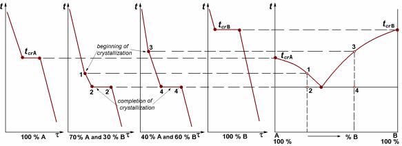
The critical points are transferred from the set of cooling curves to the plot in co-ordinates “temperature – composition” (Fig. 8.7).
а |
b |
Figure 8.7 Cooling curves (a) and phase diagram (b)
Phase diagram of alloys with unlimited solubility of components
If alloy components form unlimited solid solutions there are only two lines in the phase diagram: a line of the beginning of crystallisation and a line of the ending of crystallisation (see Fig. 8.8). Each of them is a set of critical points for all alloys of the given system.
58
Created with novaPDF Printer (www.novaPDF.com). Please register to remove this message.

Line of the beginning of crystallisation 1-2-3 is termed the liquidus line. Above this line all alloys of system are in a liquid state.
Line of the ending of crystallisation 1-4-3 is termed the solidus line. Below this line all alloys of system are in a solid state.
All alloys having such a diagram crystallize in the range of temperatures, unlike pure components A and B. Between the liquidus line and solidus line all alloys are twophase and composed of a liquid and crystals of a solid solution. After crystallisation all alloys of system are single-phase and represent a solid solution of component B in the lattice of component A (or, on the contrary, a solid solution of component A in a
lattice of component B). In the diagram, the solid solution is denoted by Greek letters, for example, .
The alloys of the system have no phase transformations in a solid state and consequently cannot be exposed to strengthening heat treatment.
Mechanical and physical properties of the alloys having such a diagram strongly differ from those of pure components. In particular, hardness, strength, electrical resistance of alloys is higher that of pure metals; on the contrary, plasticity and magnetic conductivity is lower.
According to the physical chemistry laws, the first crystals formed in a liquid contain more refractory component B, than those crystallising later. As the first crystals arise in the vicinity of mould walls, and the last – in an ingot core, the ingot can appear chemically inhomogeneous. External layers will contain more refractory component B, and a core – more fusible component A. Such a phenomenon is called liquation.
Liquation may occur inside a single crystal: in the centre it is enriched by a refractory component, and at borders – by fusible. It is microliquation, or intracrystal liquation.
Liquation is an undesirable phenomenon. Microliquation appears after solidification at high cooling rate; at slow cooling the diffusion takes enough time to occur and homogenate the structure of an alloy in a grain. Microliquation can be eliminated by diffusion annealing. Alloy is heated up to the temperatures close to solidus for a long time. But liquation in a whole volume of ingot cannot be eliminated.
59
Created with novaPDF Printer (www.novaPDF.com). Please register to remove this message.

Examples of alloys with full mutual solubility of components: Cu – Ni, Ag – Au, Mo – W, Mo – V.
Phase diagram of alloys with a total absence of components solubility
If alloy components are not dissolved in each other, either crystals of pure component A are formed from liquid (in the left part of the diagram), or crystals of pure component B (in the right part of the diagram). Then liquidus line consists of two parts: a line 1-2 on which crystallisation of component A begins, and a line 2-3 on which crystallisation of component B begins
(Fig. 8.9).
So, the liquidus in the diagram is shown as line 1-2-3. On this line crystallisation of alloys upon cooling begins (and fusion at heating finishes). Solidus of the diagram is straight line 4-2-5, parallel to concentration axes. On this line crystallisation of alloys comes to the end at cooling (and fusion begins at heating).
In the left field 1-2-4-1 component A crystallizes from the melt, hence, the
concentration of component A in a liquid decreases, and the content of component B, on the contrary, grows. In the right field 2-3-5-2 crystallization of component B occurs; thus the concentration of component B in liquid decreases, and the part of component A, on the contrary, grows.
When the temperature achieves the solidus line 4-2-5, concentration of components in a liquid corresponds to a point 2 for any alloy.
The point 2 belongs to both branches of liquidus and to both fields of crystallisation. Besides, it is situated both on the liquidus line and the solidus one. It means that the alloy 2 begins and stops to crystallize at the same temperature. In this alloy crystals A and crystals B are formed simultaneously. They should be very small as temperature of the point 2 is considerably below than temperatures of crystallisation of both components, and overcooling degree is big. Such a mixture of very small crystals of two components, crystallizing at constant and lowest temperature for the given system, is called eutectic (eutectic means “easily melted”).
60
Created with novaPDF Printer (www.novaPDF.com). Please register to remove this message.