

Constr_materials
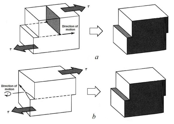
.pdfPlastic deformation corresponds to the motion of large numbers of dislocations. An edge dislocation moves in response to a shear stress applied in a direction perpendicular to its line; the mechanics of dislocation motion are represented in Figure 5.2.
Let the initial extra half-plane of atoms be plane A. When the shear stress is applied as indicated (Fig. 5.2, a), plane A is forced to the right; this in its turn pushes the top halves of planes B, C, D, and so on, in the same direction. If the applied shear stress is of sufficient magnitude, the interatomic bonds of plane B are severed along the shear plane, and the upper half of plane B becomes the extra half-plane as plane A links up with the bottom half of plane B (Fig. 5.2, b). This process is subsequently repeated for the other planes, such that the extra half-plane, by discrete steps, moves from left to right by successive and repeated breaking of bonds and shifting by interatomic distances of upper half-planes. Before and after the movement of a dislocation through some particular region of the crystal, the atomic arrangement is ordered and perfect; it is only during the passage of the extra half-plane that the lattice structure is disrupted. Ultimately this extra halfplane may emerge from the right surface of the crystal, forming an edge that is one atomic distance wide; this is shown in Figure 5.2, c.
Figure 5.2 The mechanism of dislocation motion
The process by which plastic deformation is produced by dislocation motion is termed slip; the crystallographic plane along which the dislocation line traverses is the slip plane, as indicated in Figure 5.2. Macroscopic plastic deformation simply corresponds to permanent deformation that results from the movement of dislocations, or slip, in response to an applied shear stress, as represented in Figure 5.3, a.
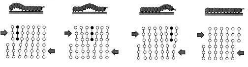
Dislocation motion is analogous to the mode of locomotion employed by a caterpillar (Fig. 5.4). The caterpillar forms a hump near its posterior end by pulling in its last pair of legs a unit leg distance. The hump is propelled
41
Created with novaPDF Printer (www.novaPDF.com). Please register to remove this message.
forward by repeated lifting and shifting of legs pair. When the hump reaches the anterior and, the entire caterpillar has moved forward by the leg separation distance. The caterpillar hump and its motion correspond to the extra half-plane of atoms in the dislocation model of plastic deformation.
Figure 5.3 The formation of a step on the crystal surface by the motion of (a) an edge dislocation and (b) a screw dislocation
The motion of a screw dislocation in response to the applied shear stress is shown in Figure 5.3, b; the direction of movement is perpendicular to the stress direction. For an edge, motion is parallel to the shear stress. However, the net plastic deformation for the motion of both dislocation types is the same (Fig. 5.3). The direction of motion of the mixed dislocation line is neither perpendicular nor parallel to the applied stress, but lies somewhere in between.
Virtually all crystalline materials contain some dislocations that were introduced during solidification, during plastic deformation, and as a consequence of thermal stresses that result from rapid cooling. The number of dislocations, or dislocation density in a material, is expressed as a total dislocation length per unit volume, or, equivalently, the number of dislocations that intersect a unit area of a random section. The units of dislocation density are millimeters of dislocation per cubic millimeter or just
42
Created with novaPDF Printer (www.novaPDF.com). Please register to remove this message.
per square millimeter. Dislocation densities as low as 103 mm-2 are typically found in carefully solidified metal crystals. For heavily deformed metals, the density may run as high as 109 to 1010 mm-2. Heat treating of a deformed metal specimen can diminish the density to the order of 105 to 106 mm-2.
Figure 5.4 Representation of the analogy between caterpillar and dislocation motion
Strain fields exist around dislocations, they are influential in determining the mobility of the dislocations, as well as their ability to multiply. When metals are plastically deformed, some fraction of the deformation energy (approximately 5 %) is retained internally; the remainder is dissipated as heat. This stored energy is a strain energy associated with dislocations. Some atomic distortion exists around the dislocation line because of the presence of the extra half-plane of atoms (see Fig. 5.1). As a consequence, there are regions in which compressive, tensile, and shear lattice strains are imposed on the neighboring atoms. Atoms immediately above and adjacent to the dislocation line are squeezed together. It can be said that these atoms experience a compressive strain relative to atoms positioned in a perfect crystal and far removed from the dislocation. Directly below the half-plane, the effect is just the opposite; lattice atoms sustain an imposed strain. For a screw dislocation, lattice strains are pure shear only. The strain fields can interact. Between two dislocations having the same sign and the identical slip plane a mutual repulsive force exists and tends to move them apart.
During plastic deformation, the number of dislocations increases dramatically. One important source of these new dislocations is existing dislocations, which multiply; grain boundaries, as well as internal defects may serve as dislocation formation sites during deformation.
Dislocations do not move with the same degree of ease on all crystallographic planes of atoms and in all crystallographic directions. Ordinarily there is a preferred plane called a slip plane, and in that plane there are specific slip directions along which dislocation motion occurs. This combination of the slip plane and the slip directions is termed the slip system. Usually the slip plane is that plane having the densest atomic packing. The
43
Created with novaPDF Printer (www.novaPDF.com). Please register to remove this message.
slip direction corresponds to the direction, in this plane, that is most closely packed with atoms. Metals with FCC or BCC crystal structures have a relatively large number of slip systems (at least 12). These metals are quite ductile because extensive plastic deformation is normally possible along the various systems. Conversely, HCP metals, having few active slip systems, are normally quite brittle.
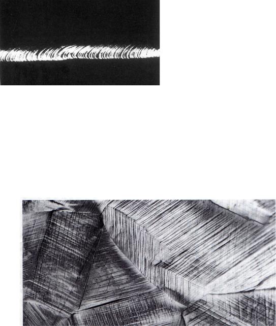
For a single-crystal specimen that is stressed in tension, slip deformation forms small steps on the surface. Each step results from the movement of a large number of dislocations along the same slip plane. On the surface of a polished single crystal specimen, these steps appear as lines, which are called slip lines. A zinc single crystal, that has been plastically deformed to the degree that these slip markings are discernible, is shown in
Figure 5.5.
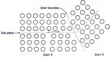
Deformation and slip in polycrystalline materials is somewhat more complex. Because of the random crystallographic orientations of the numerous grains, the direction of slip varies from one grain to another. For each, dislocation motion occurs along the slip system that has the most favorable orientation, as defined above. This is exemplified by a photomicrograph of a polycrystalline copper polished specimen that has been plastically deformed (Fig. 5.6).
Figure 5.6 Slip lines on the polished surface of a polycrystalline copper specimen after deformation
44
Created with novaPDF Printer (www.novaPDF.com). Please register to remove this message.
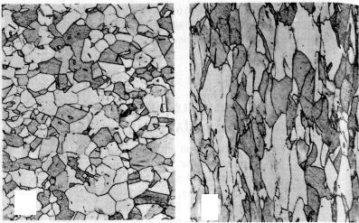
In the photo slip lines are visible, and it appears that two slip systems operated for the most of the grains, as evidenced by two sets of parallel yet intersecting sets of lines. Furthermore, variation in grain orientation is indicated by the difference in alignment of the slip lines for the several grains.
Gross plastic deformation of a polycrystalline specimen corresponds to the comparable distortion of the individual grains by means of slip. Each individual grain is constrained, to some degree, in the shape it may assume by its neighboring grains. The manner in which grains distort as a result of gross plastic deformation is indicated in Figure 5.7. Before deformation the grains are equiaxed, or have approximately the same dimension in all directions. For this particular deformation, the grains become elongated along the direction in which the specimen was elongated.
a
Figure 5.7 Alteration of the grain structure of a polycrystalline metal as a result of plastic deformation
Questions and problems
1.Give the definition of dislocation density.
2.What a confirmation of dislocation slip is visible on the surface of crystal?
3.Describe the mechanism of plastic deformation.
4.Give the reason of difference in theoretical and practically measured strength of metals.
5.Compare plastic deformation of a single crystal and polycrystalline material.
6.In what planes a dislocation slip in crystals occurs?
7.How to distinguish, whether metal was plastically deformed, or not?
45
Created with novaPDF Printer (www.novaPDF.com). Please register to remove this message.
misorientation increases.
2. The atomic disorder within a grain boundary region will result in a discontinuity of slip planes from one grain into the other.
It should be mentioned that, for high-angle grain boundaries, dislocations do not traverse grain boundaries during deformation; rather, a stress concentration ahead of a slip plane in one grain may activate sources of new dislocations in an adjacent grain.
A fine-grained material (one that has small grains) is harder and stronger that one that is coarse grained, since the former has a greater total grain boundary area to impede dislocation motion. For many materials, the
yield strength σY varies with grain size according to
σY= σ0 + kY·d-1/2.
This expression is termed the Hall-Petch equation; d is the average grain diameter, and σ0 and kY are constant for a particular material.
6.2.SOLID-SOLUTION STRENGTHENING
Another technique to strengthen and harden metals is alloying with impurity atoms that go into either substitutional or interstitial solid solution. It is solid-solution strengthening. High-purity metals are almost always softer and weaker than alloys composed of the same base metal. Increasing in concentration of the impurity results in an attendant increase in tensile and yield strength.
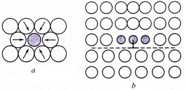
Alloys are stronger than pure metals because impurity atoms that go into solid solution ordinarily impose lattice strains on the surrounding host atoms. Lattice strain field interactions between dislocations and these impurity atoms result, and consequently, dislocation movement is restricted. For example, an impurity atom that is smaller than a host atom which it substitutes, exerts tensile strains in the surrounding crystalline lattice as illustrated in Figure 6.2, a.
Figure 6.2 Tensile lattice strains imposed on host atoms (a) and possible location of smaller impurity atoms relative to an edge dislocation (b)
47
Created with novaPDF Printer (www.novaPDF.com). Please register to remove this message.
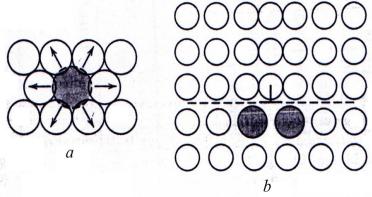
Conversely, a larger substitutional atom imposes compressive strains in its vicinity (Fig. 6.3, a). The solute atoms tend to diffuse to dislocations and segregate around them in a way so as to reduce the overall strain energy, that is, to cancel some of the strain in the lattice surrounding a dislocation. A smaller impurity atom is located adjacent to the dislocation line and above the slip plane (Fig. 6.2, b); a larger impurity atom would be situated below the slip plane (Fig. 6.3, b).
Figure 6.3 Compressive strains imposed on host atoms (a) and possible location of larger impurity atoms relative to an edge dislocation (b)
The resistance to slip is greater when impurity atoms are present because the overall lattice strain must increase if a dislocation is torn away from them. Thus, a greater applied stress is necessary to first initiate and then continue plastic deformation for solid-solution alloys, as opposed to pure metals.
6.3.STRAIN HARDENING
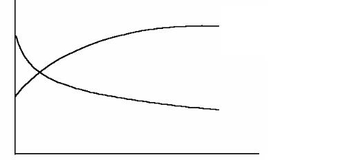
Strain hardening is the phenomenon whereby a ductile metal becomes harder and stronger as it is plastically deformed. Sometimes it is also called work hardening, or, because the temperature at which deformation takes place is “cold” relative to the absolute melting temperature of the metal, cold working. Most metals strain harden at room temperature. The price payed for this enhancement of hardness and strength is in the ductility of the metal. This is shown in Figure 6.4, in which the ductility, in percent elongation, experiences a reduction with increasing percent cold work.
The strain hardening phenomenon is explained on the basis of dislocation–dislocation strain field interactions. The dislocation density in a metal increases with deformation dramatically due to dislocation multiplication. Thus, the average distance of separation between dislocations decreases. The net result is that the motion of a dislocation is hindered by the
48
Created with novaPDF Printer (www.novaPDF.com). Please register to remove this message.
presence of other dislocations. As the dislocation density increases, this resistance to dislocation motion by other dislocations becomes more pronounced. Metal becomes harder and more able to resist to deformation and fracture.
Mechanical characteristics
|
σT – tensile strength, |
σT |
δ – percent elongation |
δ
Percent cold work
Figure 6.4 Increase in tensile strength and decrease in ductility with percent cold work
Strain hardening is often utilized to enhance the mechanical properties of metals during fabrication procedures. The effect of strain hardening may be removed by an annealing heat treatment.
Questions and problems
1.What is the principle of all strengthening techniques?
2.List three strengthening mechanisms for single-phase metal.
3.Explain, how each of strengthening mechanisms acts.
49
Created with novaPDF Printer (www.novaPDF.com). Please register to remove this message.
7. RECOVERY, RECRYSTALLIZATION AND GRAIN GROWTH
Some portion of the energy expended in deformation is stored in the metal as strain energy, which is associated with tensile, compressive, and shear zones around the newly created dislocations. From 5 to 10 % of the energy spent for deformation, turn to internal energy of a crystal.
For the majority of metals the cold-worked structure is stable at the room temperature However, heating creates conditions for redistribution of dislocations and reduction of their quantity as atoms receive additional energy and move easier between their equilibrium positions.
The properties and structures may be reverted back to the precoldworked states by appropriate heat treatment. Such a restoration results from two different processes that occur at elevated temperatures: recovery and recrystallization.
Recovery occurs at temperatures lower 0.3Tm; recrystallization requires heating to the temperatures above 0.3Tm.
7.1. RECOVERY
Recovery is a process of changes in dislocation structure and properties of the cold-worked metal under heating. The microstructure (the size and the shape of grains) remains the same in the process. During the recovery, some of the stored internal strain energy is relieved by virtue of dislocation motion, as a result of enhanced atomic diffusion at the elevated temperature. There is some reduction in the number of dislocations, and new dislocation configurations arise.
Recovery occurs in all metals subject to deformation with any strain degree. The number of vacancies and density of dislocations thus decreases. Hardness and strength decrease slightly (by 10-15 %); plasticity, on the contrary, increases.
Polygonization is developed not in all metals, after small degree of prior strain. In each grain, dislocations form “walls” or low-angle boundaries. The former grain becomes subdivided into subgrains, or polygons almost free of dislocations (Fig. 7.1). Low-angle boundaries are visible within the grains as a network of thin lines (see Figure 7.2).
a |
b |
Figure 7.1 Dislocation arrangement in a single crystal: before (a) and after (b) recovery
50
Created with novaPDF Printer (www.novaPDF.com). Please register to remove this message.