

Constr_materials
.pdfcharacteristics of these materials are extremely sensitive to the presence of minute concentrations of impurity atoms, which concentrations may be controlled over very small spatial regions. The semiconductors have made possible the advent of integrated circuitry that has totally revolutionized the electronics and computer industries (not to mention our lives) over the past two decades.
BIOMATERIALS
Biomaterials are employed in components implanted into the human body for replacement of diseased or damaged body parts. These materials must not produce toxic substances and must be compatible with body tissues (i. e., must not cause adverse biological reactions). All of the above materials
– metals, ceramics, polymers, composites, and semiconductors – may be used as biomaterials. For example, there are some of the biomaterials that are utilized in artificial hip replacements.
Materials that are utilized in high-technology (or high-tech) applications are sometimes termed advanced materials. Expression “high technology” means a device or product that operates or functions using relatively intricate and sophisticated principles.
Examples include electronic equipment computers, fiber-optic systems, spacecraft, aircraft, and military rocketry. These advanced materials are typically either traditional material, whose properties have been enhanced, or newly developed, high-performance materials. Furthermore, they may be of all material types (e. g., metals, ceramics, polymers), and are normally relatively expensive. The examples of applications of a number of advanced materials are those which are used for lasers, integrated circuits, magnetic information storage, liquid crystal displays, fiber optics.
1.4.MODERN MATERIALS’ NEEDS
In spite of the tremendous progress that has been made in the discipline of materials science and engineering within the past few years, there still remain technological challenges, including the development of even more sophisticated and specialized materials, as well as consideration of the environmental impact of materials production. Some comment is appropriate relative to these issues so as to round out this perspective.
Nuclear energy holds some promises, but the solutions of many problems that remain will necessarily involve materials, from fuels to containment structures to facilities for the disposal of radioactive waste.
Significant quantities of energy are involved in transportation. Reducing the weight of transportation vehicles (automobiles, aircraft, trains, etc.), as well as increasing engine operating temperatures, will enhance fuel
11
Created with novaPDF Printer (www.novaPDF.com). Please register to remove this message.
efficiency. New high-strength, low-density structural materials remain to be developed, as well as materials that have higher-temperature capabilities, for use in engine components.
Furthermore, there is a recognized need to find new, economical sources of energy, and to use the present resources more efficiently. Materials will undoubtedly play a significant role in these developments. For example, the direct conversion of solar into electrical energy has been demonstrated. Solar cells employ some rather complex and expensive materials. To ensure a viable technology, materials that are highly efficient in this conversion process yet less costly must be developed.
Furthermore, pollution control techniques employ various materials. In addition, materials processing and refinement methods need to be improved so that they produce less environmental degradation, that is, less pollution and less despoil age of the landscape from the mining of raw materials. Also, in some materials manufacturing processes, toxic substances are produced, and the ecological impact of their disposal must be considered.
Many materials that we use are derived from resources that are nonrenewable, that is, not capable of being regenerated. These include polymers, for which the prime raw material is oil, and some metals. These nonrenewable resources are gradually becoming depleted, which necessitates: 1) the discovery of additional reserves, 2) the development of new materials having comparable properties with less adverse environmental impact, and/or 3) increased recycling efforts and the development of new recycling technologies. As a consequence of the economics of not only production but also environmental impact and ecological factors, it is becoming increasingly important to consider the “cradle-to-grave” life cycle of materials relative to the overall manufacturing process.
The roles that materials scientists and engineers play relative to these, as well as other environmental and societal issues are vital.
Questions and problems
1.How does the society development depend on materials?
2.What were the first materials at the beginning of human era?
3.How does the study of material types influence our life?
4.What makes automobiles available in our life?
5.How do you understand the term “structure”?
6.What kind of engineer are you?
7.Why is it necessary for you to study materials and their properties?
8.What are the main criteria for selecting the right material?
9.What are the main groups of engineering materials?
10.List the steps to save nonrenewable resources.
12
Created with novaPDF Printer (www.novaPDF.com). Please register to remove this message.
2. CRYSTAL STRUCTURES: FUNDAMENTAL CONCEPTS
The present chapter is devoted to the atomic level of the materials structure, specifically, to some of the arrangements that may be assumed by atoms in the solid state.
Solid materials may be classified according to the regularity with which atoms or ions are arranged with respect to one another. A crystalline material is one in which the atoms are situated in a repeating or periodic array over large atomic distances; that is, long-range order exists, such that upon solidification, the atoms will position themselves in a repetitive threedimensional pattern, in which each atom is bonded to its nearest-neighbor atoms. All metals, many ceramic materials, and certain polymers form crystalline structures under normal solidification conditions. For those that do not crystallize, this long-range atomic order is absent; these materials are called noncrystalline or amorphous.
Some of the properties of crystalline solids depend on the crystal structure of the material, the manner in which atoms, ions, or molecules are spatially arranged. There is an extremely large number of different crystal structures all having long-range atomic order, these vary from relatively simple structures for metals, to exceedingly complex ones, as displayed by some of the ceramic and polymeric materials. The present discussion deals with several common metallic crystal structures.
When describing crystalline structures, atoms (or ions) are thought of as being solid spheres having well-defined diameters. This is termed the atomic hard sphere model in which spheres representing nearest-neighbor atoms touch one another.
An example of the hard sphere model for the atomic arrangement found in some of the common elemental metals is displayed in Figure 2.1, c. In this particular case all the atoms are identical. Sometimes the term lattice is used in the context of crystal structures; in this sense “lattice” means a three-dimensional array of points coinciding with atom positions (or sphere centers).
2.1.UNIT CELLS
The atomic order in crystalline solids indicates that small groups of atoms form a repetitive pattern. Thus, in describing crystal structures, it is often convenient to subdivide the structure into small repeat entities called unit cells. Unit cells for most crystal structures are parallelepipeds or prisms having three sets of parallel faces; one is drawn within the aggregate of spheres (Figure 2.1, c), which in this case happens to be a cube. A unit cell is chosen to represent the symmetry of the crystal structure, wherein all the
13
Created with novaPDF Printer (www.novaPDF.com). Please register to remove this message.
atom positions in the crystal may be generated by translations of the unit cell integral distances along each of its edges. Thus, the unit cell is the basic structural unit or building block of the crystal structure and defines the crystal structure by virtue of its geometry and the atom positions within. Convenience usually dictates that parallelepiped corners coincide with centers of the hard sphere atoms. Furthermore, more than a single unit cell may be chosen for a particular crystal structure; however, we generally use the unit cell having the highest level of geometrical symmetry.
a |
|
b |
|
|
|
c
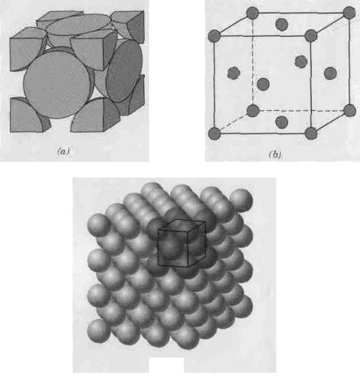
Figure 2.1 Face-centered cubic crystal structure:
a – a hard sphere unit cell representation, b – a reduced-sphere unit cell, c – an aggregate of many atoms
2.2.METALLIC CRYSTALLINE STRUCTURES
The atomic bonding in this group of materials is metallic, and thus nondirectional in nature. Consequently, there are no restrictions as to the number and position of nearest-neighbor atoms; this leads to relatively large
14
Created with novaPDF Printer (www.novaPDF.com). Please register to remove this message.

numbers of nearest neighbors and dense atomic packings for most metallic crystal structures. Also, for metals, using the hard sphere model for the crystal structure, each sphere represents an ion core. Table 2.1 presents the atomic radius for a number of metals. Three relatively simple crystal structures are found for most of the common metals: face-centered cubic, body-centered cubic and hexagonal close-packed.
The face-centered cubic crystal structure
The crystal structure found for many metals has a unit cell of cubic geometry, with atoms located at each of the corners and the centers of all the cube faces. It is aptly called the face-centered cubic (FCC) crystal structure. Some of the familiar metals having this crystal structure are copper, aluminum, silver, and gold (Table 2.1). Figure 2.1, a shows a hard sphere model for the unit cell, whereas in Figure 2.1, b the atom centers are represented by small circles to provide a better perspective of atom positions. The aggregate of atoms in Figure 2.1, с represents a section of crystal consisting of many FCC unit cells. These spheres or ion cores touch one another across a face diagonal; the cube edge length a and the atomic radius R are related through
|
|
a 2R |
2 . |
(2.1) |
|
|
|
Table 2.1 Atomic Radius and Crystal Structures of Metals |
|||||||
Metal |
Crystal |
Atomic |
Metal |
Crystal |
Atomic Radius |
||
Structure |
Radius (nm) |
Structure |
(nm) |
||||
|
|
|
|||||
|
|
|
|
|
|
||
Aluminum |
FCC |
0.1431 |
Molybdenum |
BCC |
0.1363 |
||
Cadmium |
HCP |
0.1490 |
Nickel |
|
FCC |
0.1246 |
|
Chromium |
BCC |
0.1249 |
Platinum |
|
FCC |
0.1387 |
|
Cobalt |
HCP |
0.1253 |
Silver |
|
FCC |
0.1445 |
|
Copper |
FCC |
0.1278 |
Tantalum |
|
BCC |
0.1430 |
|
Gold |
FCC |
0.1442 |
Titanium (α) |
HCP |
0.1445 |
||
Iron (α) |
BCC |
0.1241 |
Tungsten |
|
BCC |
0.1371 |
|
Lead |
FCC |
0.1750 |
Zinc |
|
HCP |
0.1332 |
|
|
|
|
|
|
|
|
|
For the FCC crystal structure, each corner atom is shared among eight unit cells, whereas a face-centered atom belongs to only two. Therefore, one eighth of each of the eight corner atoms and one half of each of the six face atoms, or a total of four whole atoms, may be assigned to a given unit cell. This is depicted in Figure 2.1, a, where only sphere portions are represented within the confines of the cube. The cell comprises the volume of the cube, which is generated from the centers of the corner atoms.
15
Created with novaPDF Printer (www.novaPDF.com). Please register to remove this message.

Corner and face positions are really equivalent; that is, translation of the cube corner from an original corner atom to the center of a face atom will not alter the cell structure.
Two other important characteristics of a crystal structure are the coordination number and the atomic packing factor (APF). For metals, each atom has the same number of nearest-neighbour or touching atoms, which is the coordination number. For face-centred cubic structure, the coordination number is 12. This may be confirmed by examination of Figure 2.1, a; the front face atom has four corner nearest-neighbor atoms surrounding it, four face atoms that are in contact from behind, and four other equivalent face atoms residing in the next unit cell to the front, which is not shown.
The APF is the fraction of solid sphere volume in a unit cell, assuming the atomic hard sphere model, or
|
Volume of atoms in a unit cell |
|
|
APF = |
|
. |
(2.2) |
|
|||
|
Total unit cell volume |
|
|
For the FCC structure, the atomic packing factor is 0.74, which is the maximum packing possible for spheres all having the same diameter. Computation of this APF is also included as an example problem. Metals typically have relatively large atomic packing factors to maximize the shielding provided by the free electron cloud.
The body-centered cubic crystal structure
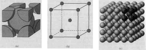
Another common metallic crystal structure also has a cubic unit cell with atoms located at all eight corners and a single atom at the cube center. This is called a body-centered cubic (BCC) crystal structure. A collection of spheres depicting this crystal structure is shown in Figure 2.2, c, whereas Figures 2.2, a and 2.2, b are diagrams of BCC unit cells with the atoms represented by hard sphere and reduced-sphere models, respectively. Center and corner atoms touch one another along cube diagonals, and unit cell length a and atomic radius R are related through
a |
4R |
|
||
|
|
(2.3) |
||
|
3 |
|||
|
|
|
||
16
Created with novaPDF Printer (www.novaPDF.com). Please register to remove this message.
a |
|
b |
|
c |
|
|
|
|
|
Figure 2.2 Body-centered cubic crystal structure:
a – a hard sphere unit cell representation, b – a reduced-sphere unit cell, c – an aggregate of many atoms
Chromium, iron, tungsten, as well as several other metals listed in Table 2.1 exhibit a BCC structure.
Two atoms are associated with each BCC unit cell: the equivalent of one atom from the eight corners, each of which is shared among eight unit cells, and the single center atom, which is wholly contained within its cell. In addition, corner and center atom positions are equivalent. The coordination number for the BCC crystal structure is 8; each center atom has as nearest neighbors its eight corner atoms. Since the coordination number is less for BCC than FCC, so also is the atomic packing factor for BCC lower – 0.68 versus 0.74.
Hexagonal close-packed crystal structure
Not all metals have unit cells with cubic symmetry; the final common metallic crystal structure to be discussed has a unit cell that is hexagonal. Figure 2.3, а shows a reduced-sphere unit cell for this structure, which is termed hexagonal close-packed (HCP); an assemblage of several HCP unit cells is presented in Figure 2.3, b. The top and bottom faces of the unit cell consist of six atoms that form regular hexagons and surround a single-atom in the centre. Another plane that provides three additional atoms to the unit cell is situated between the top and bottom planes. The atoms in this midplane have as nearest neighbours atoms in both of the adjacent two planes. The equivalent of six atoms is contained in each unit cell; one-sixth of each of the 12 top and bottom face corner atoms, one-half of each of the 2 centre face atoms, and all the 3 midplane interior atoms. If a and c represent, respectively, the short and long unit cell dimensions of Figure 2.3, a, the c/a ratio should be 1.633; however, for some HCP metals this ratio deviates from the ideal value.
17
Created with novaPDF Printer (www.novaPDF.com). Please register to remove this message.
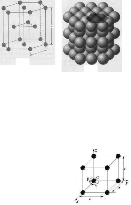
The coordination number and the atomic packing factor for the HCP crystal structure are the same as for FCC: 12 and 0.74, respectively. The HCP metals include cadmium, magnesium, titanium, and zinc.
a
b
Figure 2.3 Hexagonal close-packed crystal structure:
a – a reduced sphere unit cell (a and c represent the short and long edge lengths), b – aggregate of many atoms
2.3.CRYSTAL SYSTEMS
Since there are many different possible crystal structures, it is sometimes conveniently to divide them into groups according to unit cell configurations and atomic arrangements. One such scheme is based on the unit cell geometry, that is, the shape of the appropriate unit cell parallelepiped without regard to the atomic positions in the cell. Within this framework, an x, y, z coordinate system is established with its origin at one of the unit cell corners; each of the x, y, and z axes coincides with one of the three parallelepiped edges that extend
from this corner, as illustrated in Figure 2.4. The unit cell geometry is completely defined in terms of six parameters: the three edge lengths a, b, and c, and the three interaxial angles α, β and γ. These are indicated in Figure 2.4, and are sometimes termed the lattice parameters of a crystal structure.
On this basis there are found crystals having seven different possible combinations of a, b, and c,
18
Created with novaPDF Printer (www.novaPDF.com). Please register to remove this message.

and α, β and γ, each of which represents a distinct crystal system. These seven crystal systems are cubic, tetragonal, hexagonal, orthorhombic, rhombohedral, monoclinic, and triclinic. The lattice parameter relationships and unit cell sketches for each are represented in Table 2.2.
Table 2.2 Lattice Parameter Relationships Showing Unit Cell Geometries for the Seven Crystal Systems
Crystal System |
Axial Relationship |
Interaxial Angles |
Unit Cell Geometry |
|||
|
|
|
|
|
|
|
Cubic |
|
a = b = c |
|
α = β = γ = 90° |
|
|
|
|
|
|
|
|
|
Hexagonal |
|
a = b ≠ c |
|
α = β = 90°, |
|
|
|
|
γ = 120° |
|
|||
|
|
|
|
|
||
|
|
|
|
|
|
|
Tetragonal |
|
a = b ≠ c |
|
α = β = γ = 90° |
|
|
|
|
|
|
|
|
|
Rhombohedral |
|
a = b = c |
|
α = β = γ ≠ 90° |
|
|
|
|
|
|
|
|
|
Orthorhombic |
|
a ≠ b ≠ c |
|
α = β = γ = 90° |
|
|
|
|
|
|
|
|
|
Monoclinic |
|
a ≠ b ≠ c |
|
α = γ = 90° ≠ β |
|
|
|
|
|
|
|
|
|
Triclinic |
|
a ≠ b ≠ c |
|
α ≠ β ≠ γ ≠ 90° |
|
|
|
|
|
|
|
|
|
The cubic system, for which a = b = c and α = β = γ = 90°, has the greatest degree of symmetry. Least symmetry is displayed by the triclinic system, since a ≠ b ≠с and α ≠ β ≠ γ. From the discussion of metallic crystal structures, it should be apparent that both FCC and BCC structures belong to the cubic crystal system, whereas HCP falls within hexagonal. The
19
Created with novaPDF Printer (www.novaPDF.com). Please register to remove this message.

conventional hexagonal unit cell really consists of three parallelepipeds situated as shown in Table 2.2.
It is important to note that many of the principles and concepts in previous addressed discussions in this chapter also apply to crystalline ceramic and polymeric systems. For example, crystal structures are most often described in terms of unit cells, which are normally complex than those for FCC, BCC, and HCP. In addition, for these other more systems, we are often interested in determining atomic packing factors and densities, using modified forms of Equations 2.2 and density computation. Furthermore, according to unit cell geometry, crystal structures of these other material types are grouped within the seven crystal systems.
2.4.SINGLE CRYSTALS
For a crystalline solid, when the periodic and repeated arrangement of atoms is perfect or extends throughout the entirety of the specimen without interruption, the result is a single crystal. All unit cells interlock in the same way and have the same orientation. Single crystals exist in nature, but they may also be produced artificially. They are ordinarily difficult to grow, because the environment must be carefully
controlled.
If the extremities of a single crystal are permitted to grow without any external constraint, the crystal will assume a regular geometric shape having flat faces, as with some of the gem stones; the shape is indicative of the crystal structure. A photograph of several single crystals is shown in Figure 2.5. Within the past few years, single crystals have become extremely important in many of our modern technologies, in particular electronic microcircuits, which employ single crystals of silicon and other semiconductors.
2.5.POLYCRYSTALLINE MATERIALS
Most crystalline solids are composed of a collection of many small crystals or grains; such materials are termed polycrystalline. Various stages in the solidification of a polycrystalline specimen are represented schematically in Figure 2.6. Initially, small crystals or nuclei form at various positions. These have random crystallographic orientations, as indicated by the square grids. The small grains grow by the successive addition from the surrounding liquid of atoms to the structure of each. The extremities of
20
Created with novaPDF Printer (www.novaPDF.com). Please register to remove this message.