

Build The Ultimate Custom PC (2005)
.pdfChapter 10 — A Tour of Cables and Fittings 139
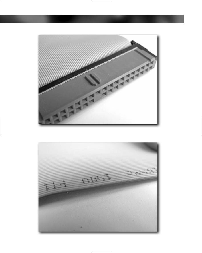
FIGURE 10-3: Floppy drive cable.
Some of the photos you will see in this chapter are of a single type of motherboard, so there may be some significant differences between what you see here and what you have at home. Check the manuals for your devices for specifics relating to connector location on the board and specific pin layouts.
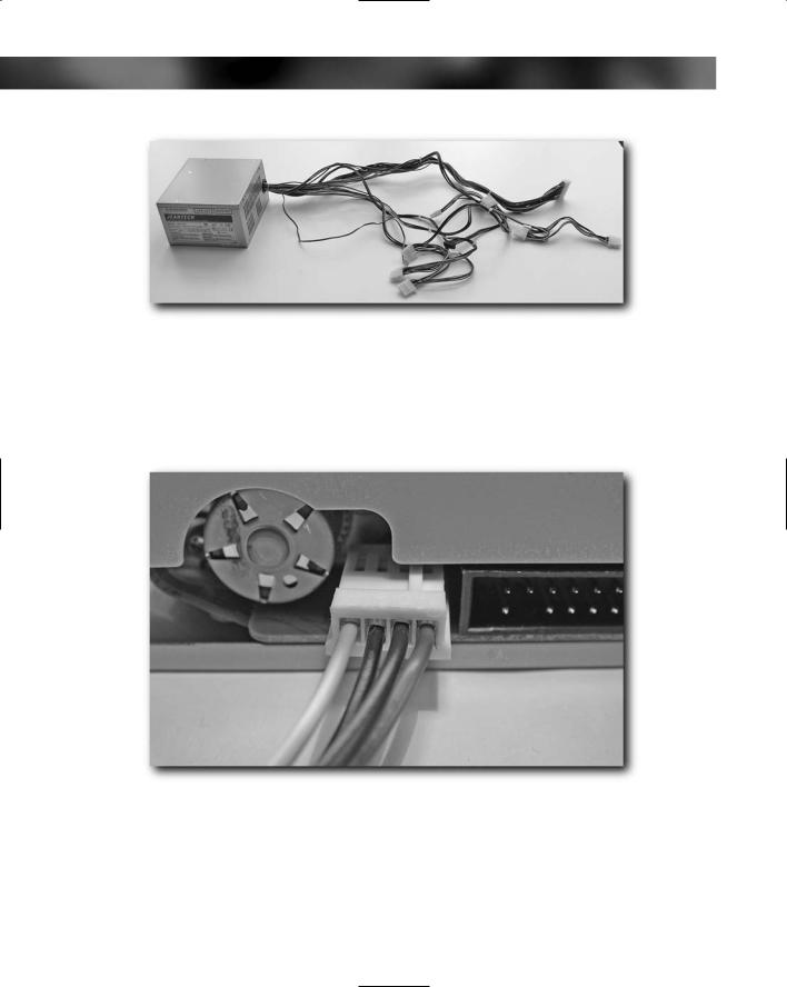
Each of these three cable types stem from the power supply unit. Generally, you will find that you have one motherboard power connector, four cables for drives and two for floppy drives (although only one of these is ever used nowadays). See Figure 10-4.
140 Part I — Choosing Components for Your PC
FIGURE 10-4: Full wiring loom from a 350-watt PSU.
On some motherboards, you may also find auxiliary power cables. Each of these cables has a distinct connector at the end, so there is no chance that you will get confused. In addition to the connector, each cable is keyed to prevent it from fitting incorrectly into the device (see Figure 10-5).
FIGURE 10-5: The keyed cable fitting into a floppy drive.
Chapter 10 — A Tour of Cables and Fittings 141
These are all little touches that make life much easier for people who build and upgrade computers, and they eliminate problems and damage caused by incorrect wiring.
When you are building your PC, you should have a basic set of cabling all ready. The PSU will supply all the cabling when it comes to power needs.
That’s all the power cabling inside a PC. You can easily spot them all because they all come from the PSU.
Let’s now look at the front panel connectors.
Front Panel Connectors
When you look at the front of a PC, you’ll notice that there are a number of LEDs and buttons there to control or get feedback from the PC. Typically, you will find a:
Power on switch
Reset button
Hard drive LED
Power on LED
Although these aren’t essential items (well, okay, the power on button is if you want to get your PC going, you can live without all the others), it’s a good idea to hook them up to the motherboard in order to make sure that everything works.
LED is short of “light-emitting diode.” An LED is a little component that glows brightly when power is put through it.
142 Part I — Choosing Components for Your PC
Each of these will have cables reading from the front panel that need to be connected to the appropriate head on the motherboard:
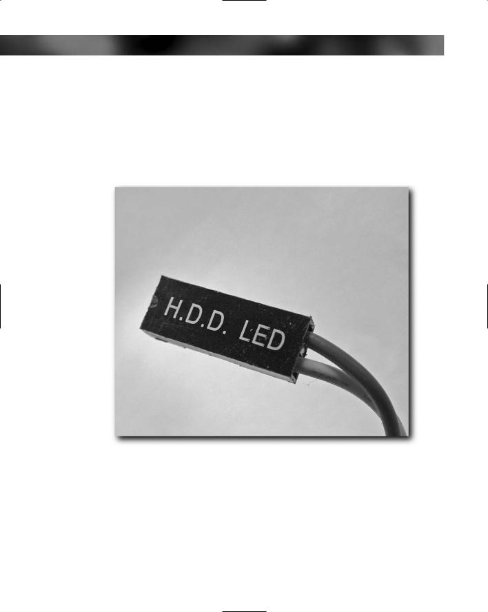
Hard drive LED (see Figure 10-6)
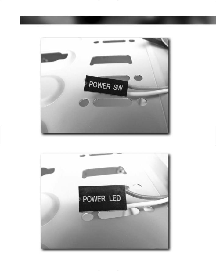
Power switch (see Figure 10-7)
Power LED (see Figure 10-8)
Reset button (see Figure 10-9)
FIGURE 10-6: Hard drive LED lead.
Chapter 10 — A Tour of Cables and Fittings 143
FIGURE 10-7: Power switch lead.
FIGURE 10-8: Power LED lead.
144 Part I — Choosing Components for Your PC
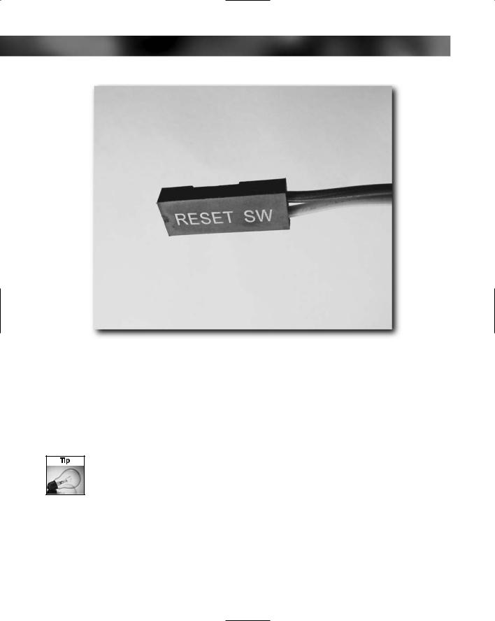
FIGURE 10-9: Reset button lead.
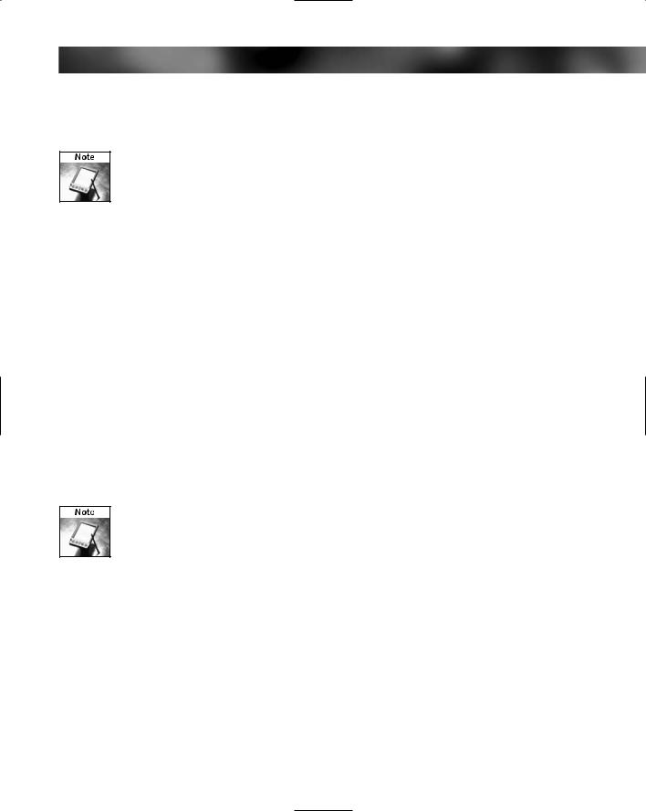
These four connectors are all attached onto the PC case and fit onto the motherboard. Each of the connectors on the ends of the wires should be clearly labeled, as should the connections on the motherboard (see Figure 10-10). Generally, these are on cables that are long enough to reach the back of the case because the case makers don’t know where the motherboard makers will put the connector heads. Typically, if you have a good case, these will all be marked up nice and clear to make fitting easy, but there are a few case makers that just stick labels on the cables that can fall off and become illegible.
If your case cables are marked with paper labels, then do yourself a favor and cover these labels with tape so that they last longer. This will prevent them becoming dirty and unreadable.
Chapter 10 — A Tour of Cables and Fittings 145
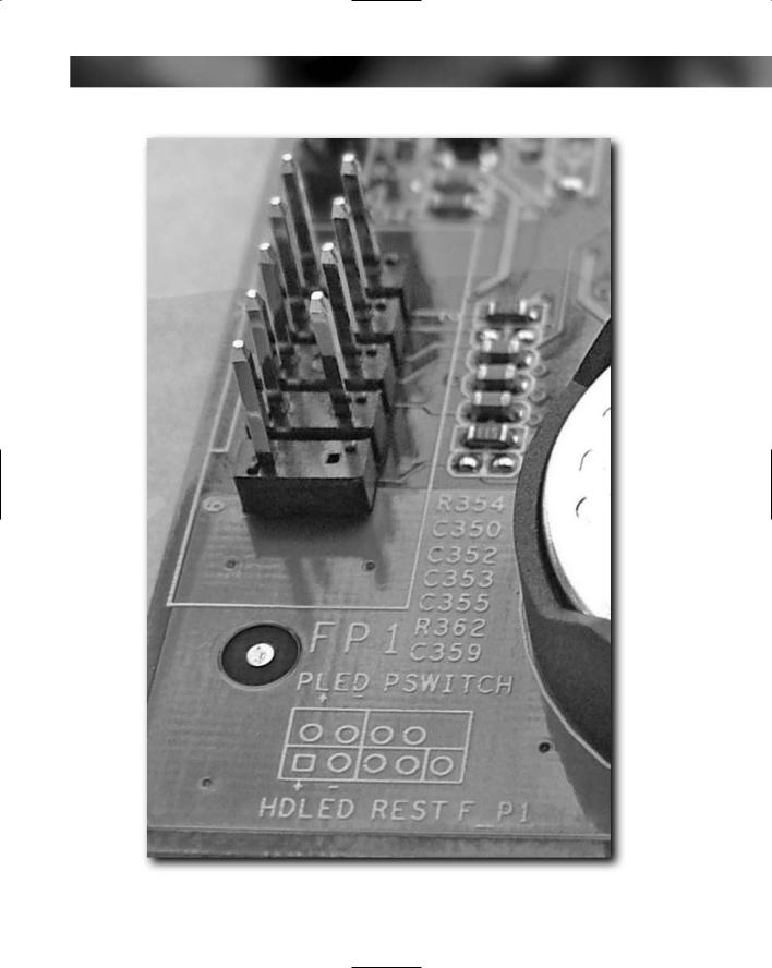
FIGURE 10-10: Front panel connector head on the motherboard.
146 Part I — Choosing Components for Your PC
Both of the cables for the LEDs require fitting the right way. You must match the polarity on the connector with the polarity on the motherboard; otherwise they won’t illuminate. The orientation of the power and reset switch connectors is unimportant, however. These cables just connect to a simple switch.
The case will have all the front panel wiring already hooked up. All you will need to do is connect it to the motherboard.
Hard Drive Data Cables
After the PSU, the hard drive and optical drive data cables add the greatest cable bulk to the inside of a PC. A lot of this bulk is due to the fact that these cables usually come as a ribbon that can be inflexible and hard to take control of. It is possible to get round data cables, but the main problems with these is that what you gain in terms of a smaller cross-section you lose in terms of ease of use and flexibility. Round data cables can be very hard to bend into shape because they are so stiff.
Serial ATA (or SATA) cabling is much smaller and easier to route than the wide IDE cables for PATA drives.
The typical PC makes use of up to two hard drive data cables. Each cable that is used to carry data to and from PATA (Parallel ATA) drives has three connectors (see Figure 10-11):
One that fits onto the motherboard. These connectors are generally colored-coded blue for easy recognition.
Two for devices. The master or primary device, which is generally a hard drive, goes on the end.
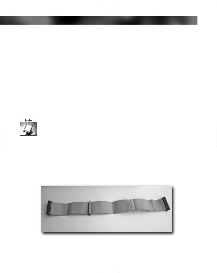
FIGURE 10-11: PATA hard drive/CD/DVD drive 40-pin, 80-wire cable.
Chapter 10 — A Tour of Cables and Fittings 147
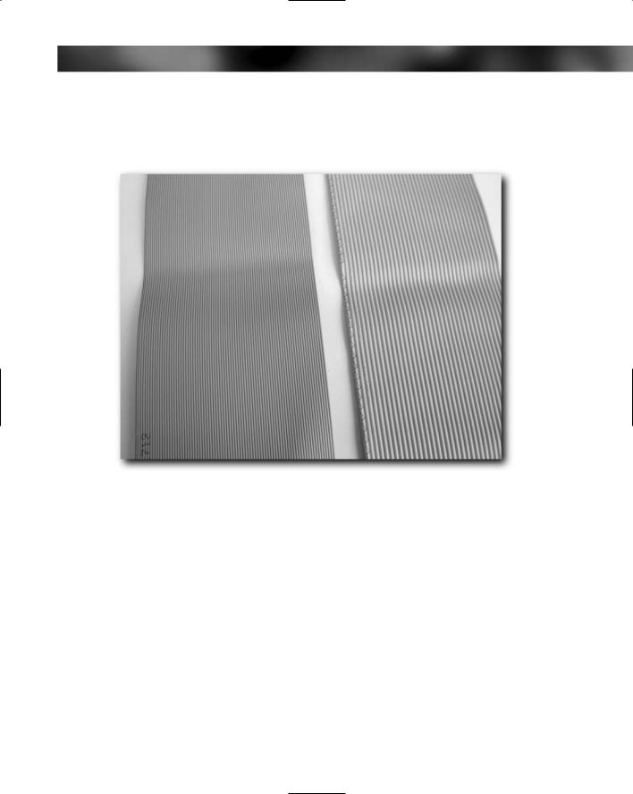
Hard drive data cables are 40-pin, 80-wire cables (avoid older 40-wire cables) and are usually in the form of a ribbon. However, many places now sell them as a round cable instead of a ribbon (see Figure 10-12).
FIGURE 10-12: An 80-wire cable (left) and 40-wire cable (right).
All the hard drive data connectors are keyed to prevent them from being improperly attached (see Figure 10-13), but there’s also another feature to help prevent mistakes — the cable running from pin 1 is generally marked with a red line on the cable and pin 1 on the drive is usually highlighted by a small mark or stamp (see Figure 10-14).
148 Part I — Choosing Components for Your PC
FIGURE 10-13: Keyed motherboard connector.
FIGURE 10-14: Red stripe indicating pin 1.