

Build The Ultimate Custom PC (2005)
.pdfChapter 11 — Checking and Testing Components 169
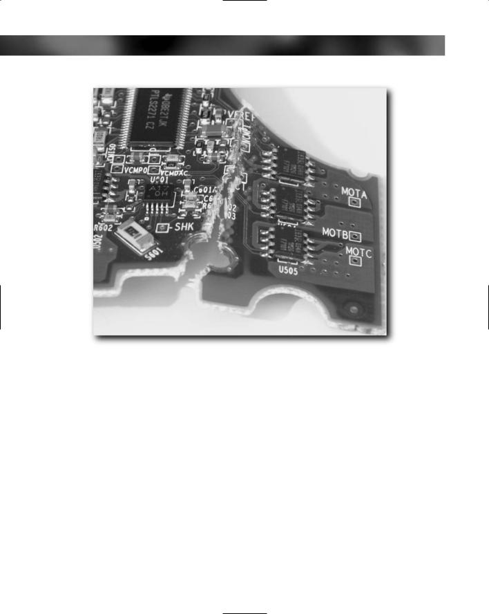
FIGURE 11-1: Carrying out a visual check for warped circuit board.
FIGURE 11-2: A crack in a circuit board.
170 Part I — Choosing Components for Your PC
FIGURE 11-3: Components damaged by a crack.
None of these are good for a board, and prevention is a lot better than cure (which means a new board). Here are ways you can protect your circuit board:
Store your board safely in its original packaging until needed.
Support the board well when carrying it out of the box.
Do not use circuit boards as trays to carry other things!
Never place anything on top of a board.
Never bend or flex the board.
Be careful not to jam it when fitting.
There are a number of ways to check for cracks in a circuit board.
A good way to check for actual physical damage is to hold the board up to strong light (sunlight is ideal, but artificial light will work) and look through it. The light will stream through cracks and make them easy to spot.
Chapter 11 — Checking and Testing Components 171
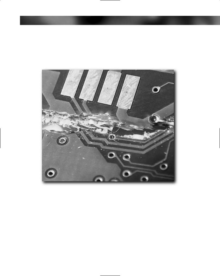
If you see a crack, examine the area of the crack carefully with a magnifier and a flashlight. You might be lucky and find that the crack is somewhere away from components and the circuit pathways in the board. Damage to the circuit board substrate isn’t in and of itself fatal to the device but if any of the pathways are damaged (see Figure 11-4) or if it has damaged the components on the board, that spells bad news for the device.
FIGURE 11-4: Crack through the circuit board wiring.
Component Damage
Generally, circuit boards have components mounted on at least one side of the circuit board. RAM modules, for example, quite often have components on both sides. These components are usually made up of a good mixture of capacitors, resistors, LEDs, chips, and other devices that are actually quite robust despite their small size and fragile appearance. But this doesn’t mean you should go testing how robust these tiny components actually are — at least not with devices you want to later use. Destructive testing on dead devices, however, can be quite fun and educational.
172 Part I — Choosing Components for Your PC
There are two ways that a component can be damaged:
It can be physically damaged or broken.
It can be knocked off the surface of the circuit board.
Checking for component damage or missing components involves carefully examining the circuit board with a magnifier and a flashlight looking for anything out of the ordinary. This isn’t as long a job as it might at first seem, but it is a bit tedious.
You can examine a circuit board in two ways:
Start at one corner and go around the board in a spiral pattern until you reach the middle.
Start at one end and work across the board in strips.
Both methods work equally well, but the method where you work in a spiral pattern around the board generally means handling the board a lot less, which is preferable.
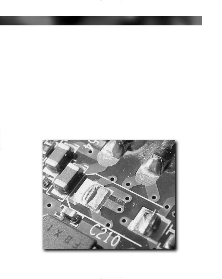
A broken component is quite easy to spot. You will notice that components are generally smooth but that a broken component is rough and jagged. Missing components often leave solder remnants on the circuit board (see Figure 11-5).
FIGURE 11-5: Missing component on circuit board.
Chapter 11 — Checking and Testing Components 173
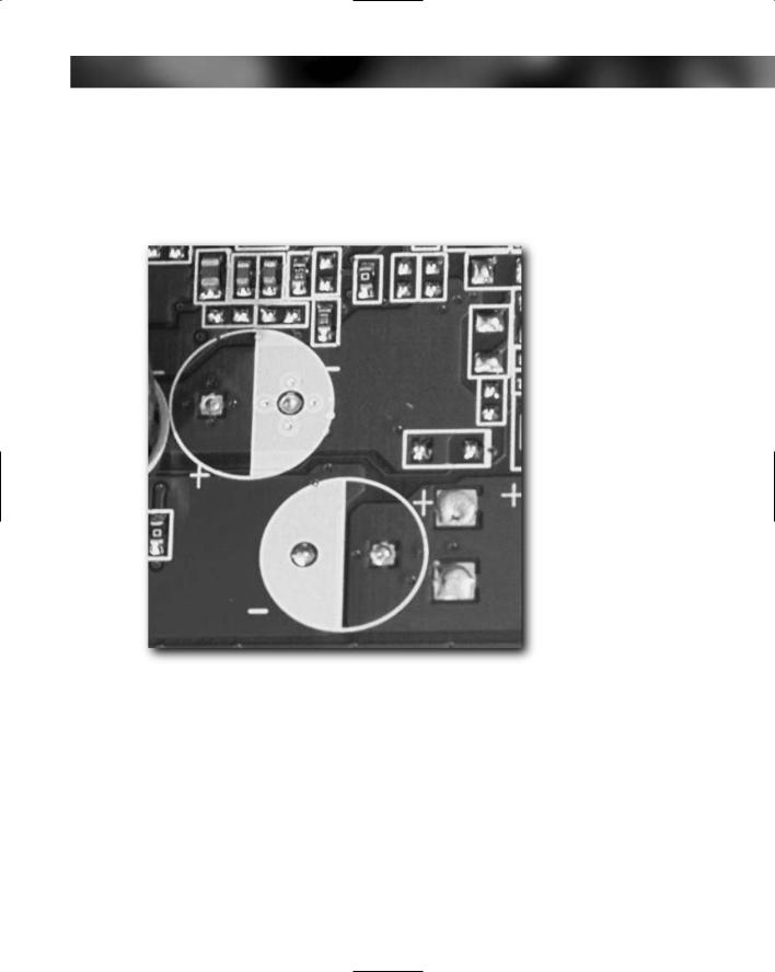
It’s worth noting that sometimes it appears that components have been knocked off a circuit board when in fact they were never placed there in the first place (see Figure 11-6). Circuit boards are quite often designed to cater for a number of models in a range, and the difference in models is due to the components fitted. You can normally tell the difference because no solder remnants will be present at the site of the component.
FIGURE 11-6: These are unused mountings that make the board look like capacitors have been knocked off.
Pins and Connectors
Both pins and connectors are susceptible to damage both during manufacture and transit and also from sloppy or careless handling. A bent pin on pretty much any device that you connect to a PC will mean that that device will probably not work. And because pins are small and it’s hard inside a PC to test for continuity, it can be difficult to troubleshoot problems caused by bent pins.
174 Part I — Choosing Components for Your PC
The same is true for connectors. A damaged connector can, while it is being inserted into a connector, damage the pins on the connectors, too. Because of this real risk of bending or breaking off pins, it is important to check pins for straightness and connectors for any damage.
There are a lot of pin-style connectors in a PC. The main circuit board component that has the most pins is the motherboard.
To check your pins and connectors, you’ll need your magnifier and flashlight. With both of these items handy, carefully check all the pins, paying special attention to any that seem bent. If you happen to come across a bent pin, the best fix is to try to straighten it with tweezers. Work slowly and don’t overbend the pin as this is a sure route to breaking it. A bent pin is bad enough, but a broken pin spells real trouble and can be virtually impossible to fix.
A broken pin can spell death for a component, but if you are handy with a soldering iron (or know someone who is), then one possible fix is to try to solder the broken pin back on. It’s not easy and the joint has to be very good, but it is a possible “last resort” fix for any broken pins you might come across.
Connector Edges
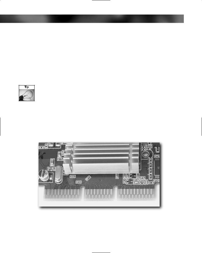
Check all the connector edges on circuit boards, especially the connector edges on expansion cards (see Figures 11-7 and 11-8). Look for twists or kinks in the board, which could harm the motherboard slot (this damage usually occurs when cards are dropped). The edges of the connectors are usually smooth and straight, so you are really looking for anything that might prevent the card from slipping into the expansion slot.
FIGURE 11-7: Good connector edges.
Chapter 11 — Checking and Testing Components 175
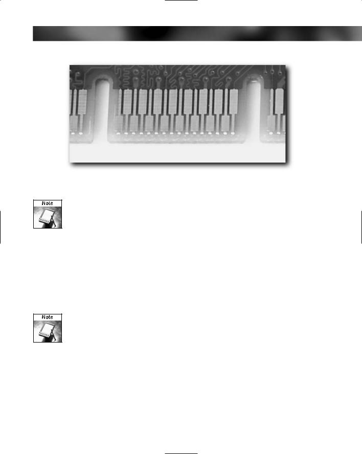
FIGURE 11-8: A notch on an AGP connector. This is normal.
Notches on the connector edge of the expansion card are common and nothing to worry about.
Checking Hard Drives
Because all of your data is going onto your hard drive, it’s important to give your hard drive a thorough check over before fitting it into the PC.
We’re assuming here that the drive that you have bought has been well packaged while in the store and during any transit in the mail or by carrier. The drive should be packaged in such a way that there is at least one good inch of insulation all around the drive. If you suspect that a drive has been mistreated in transit or while in the store, avoid it and get another from somewhere that takes better care of them.
The advice here can also be equally applied to internally fitted CD or DVD drives. The main difference is that label damage on a CD or DVD drive doesn’t matter and that there normally isn’t a visible circuit board on optical drives.
The following sections provide advice for the things you want to look for on a hard drive.
The Drive Exterior
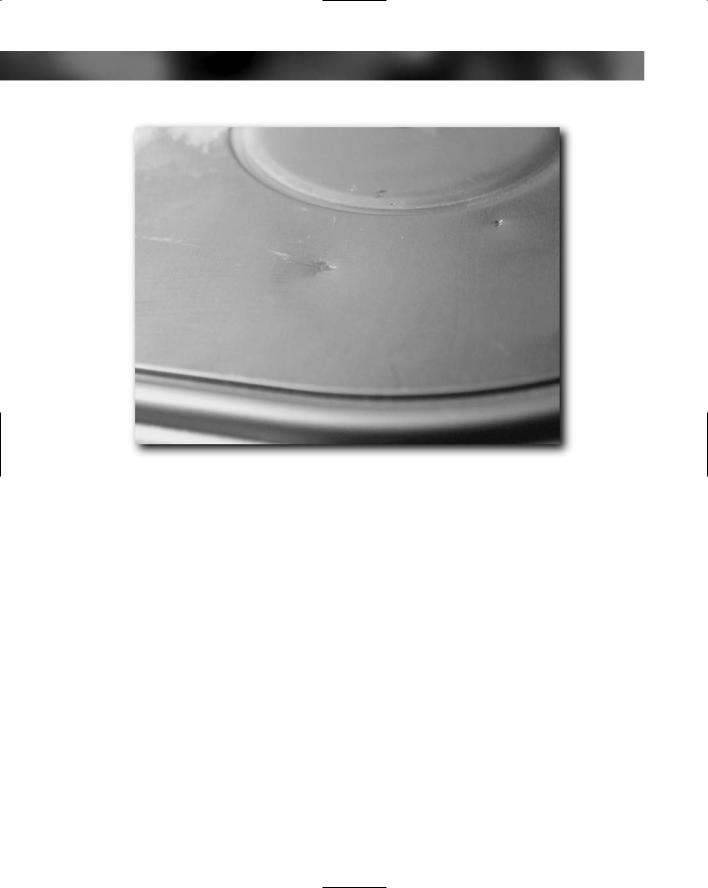
Check the outer casing of the drive for any obvious signs of physical damage (see Figure 11-9). Knocks and dents to the outer casing are not usually good news, and even the smallest dent to the metal cover of the drive can mean that the drive has a much shorter life than it should have. You need a significant amount for force to make a dent in the metal case, and this translates into a lot of energy being carried into the drive to cause damage (especially causing the heads to scrape across the platters). Also, a dent may warp the casing, allowing air to leak into the drive, carrying with it harmful dirt and dust.
176 Part I — Choosing Components for Your PC
FIGURE 11-9: Even a small dent in the casing is bad for a hard drive.
Of equal importance is looking for damage to labels. Although these might seem cosmetic, it can void your warranty or even damage the drive. Some of the labels on a drive hide actual holes into the drive, which, if you uncover them, can allow in dirt that will damage the drive.
Pins and Connectors
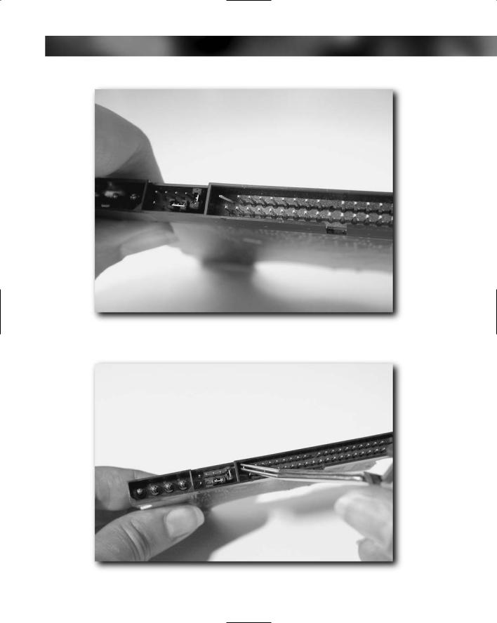
Check the pins on the rear of the drive for damage (bearing in mind that pin 19 is not usually present on hard drives). Carefully straighten any bent pins that you find (see Figure 11-10), both on the data connector and the power connector (bent power connector pins are rare given their thickness). Again, the best fix is to try to straighten the bent pin with tweezers (see Figure 11-11). Work slowly, and don’t overbend the pin. Broken pins usually mean a replacement drive.
Chapter 11 — Checking and Testing Components 177
FIGURE 11-10: Bent pin on hard drive connector.
FIGURE 11-11: Using tweezers to straighten the pin.
178 Part I — Choosing Components for Your PC
Circuit Board
Check the circuit board on the base of the hard drive. On some drives this will be covered by a rubber or metal plate. If this is the case, don’t remove the rubber or the plate to have a look because this might void your warranty. If the circuit board is uncovered, refer to the information covered in the preceding “Circuit Boards” section. Visually inspect your circuit board before progressing, looking in particular for component damage.
Checking the CPU
There’s not a lot to check on a CPU, but nonetheless it’s an important part of the checking process.
Pins
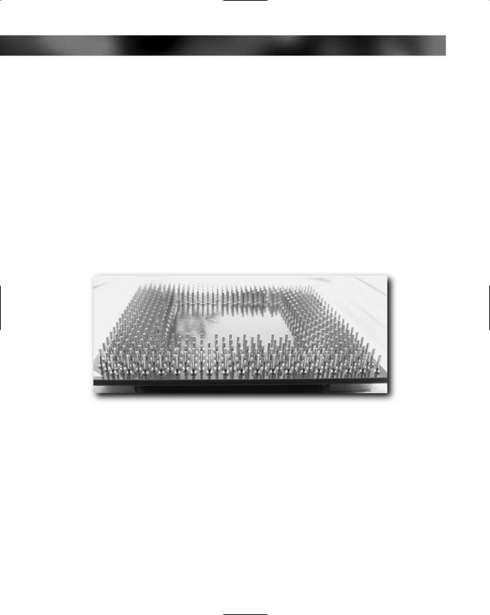
The area most prone to damage on a CPU is the sea of pins on its underside (see Figure 11-12). This isn’t as hard to spot as you might think, because one pin out of alignment actually stands out against the hundreds of straight pins!
FIGURE 11-12: All pins 100% straight!
Exterior Physical Damage
Quickly inspect the CPU for any exterior damage. This is extremely rare and only happens where either the CPU has been dropped when out of the protective packaging or where the packaging has been extensively damaged in transit.
Checking RAM Modules
RAM modules are basically small circuit boards, like mini-expansion-cards. They have circuitry on the board and a connector edge. Inspect RAM modules as you would inspect any other circuit board. Check in particular for bending and cracks.