

Broadband Packet Switching Technologies
.pdf268 CLOS-NETWORK SWITCHES
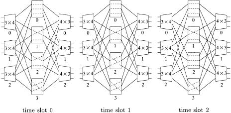
Fig. 10.10 Example of desynchronization effect in CRRD Žn s m s k s 2..
How the pointers are desynchronized is demonstrated by using a simple example. Let us consider n s m s k s 2 as shown in Figure 10.10. We assume that every VOQ is always occupied with cells. Each VOQ sends a request to be selected as a candidate at every time slot. All the pointers are set to be PV Ži, ®. s 0, PLŽi, r . s 0, and PcŽr, j. s 0 at the initial state. Only one iteration in phase 1 is considered here.
At time slot T s 0, since all the pointers are set to 0, only one VOQ in
IMŽ0., which is VOQŽ0, 0, 0., can send a cell with |
LiŽ0, |
0. through CMŽ0.. |
||||
The related pointers |
with |
the grant, PV Ž0, 0., PLŽ0, 0., |
and |
PcŽ0, 0., are |
||
updated from 0 to |
1. At |
T s 1, three VOQs, |
which |
|
are |
VOQŽ0, 0, 0., |
VOQŽ0, 1, 0., and VOQŽ1, 0, 0., can send cells. The related pointers with the grants are updated. Four VOQs can send cells at T s 2. In this situation, 100% switch throughput is achieved. There is no contention at the CMs from T s 2, because the pointers are desynchronized.
10.5THE PATH SWITCH
If we consider each input module and each output module as a node, a particular connection pattern in the middle stage of the Clos network can be
THE PATH SWITCH |
269 |
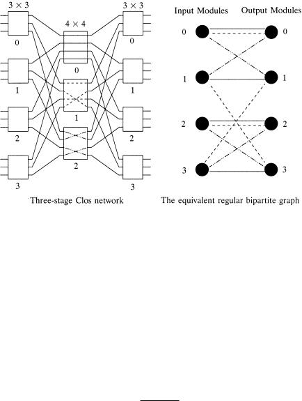
Fig. 10.11 The correspondence between the middle-stage route scheduling in a Clos network and the edge coloring of the regular bipartite multigraph. Ž 1997 IEEE..
represented by a regular bipartite multigraph with node degree m as illustrated in Figure 11.11, where each central module corresponds to a group of n edges, each connecting one distinct pair of inputroutput nodes Žmodules..
Suppose the routing algorithm of the Clos network is based on dynamic cell switching, and the amount of traffic from input module Ii to output module Oj is i j cells per time slot. The connection pattern will change in every time slot according to arrival packets, and the routing will be calculated
on slot-by-slot basis. Let |
ei jŽt. be the number of edges from Ii to Oj |
of the |
corresponding bipartite multigraph in time slot t. Then the capacity |
Ci j of |
|
the virtual path between |
Ii and Oj must satisfy |
|
Ci j s lim
T™
T |
|
|
|
Ý ei j Ž t . |
|
|
|
ts1 |
i j . |
Ž10.4. |
|
T |
|||
|
|
On the other hand, the routing of a circuit-switched Clos network is fixed, and the connection pattern will be the same in every time slot. The capacity satisfies
Ci j s ei j Ž t . s ei j i j , |
Ž10.5. |
|
which implies that the peak bandwidth Ci j |
is provided for each virtual circuit |
|
at call setup time, and it does not take |
the statistical |
multiplexing into |
270 CLOS-NETWORK SWITCHES
consideration at all. We conceived the idea of quasistatic routing, called path switching, using a finite number of different connection patterns in the middle stage repeatedly, as a compromise of the above two extreme schemes.
For any given i j, if Ýi i j n F m, and Ýj i j n F m, we can always find a finite number f of regular bipartite multigraphs such that
f
Ý ei j Ž t .
ts1 |
|
i j |
, |
Ž10.6. |
|
|
|||
|
f |
|
|
|
where ei jŽt. is the number of edges from node i to node j in the t th bipartite multigraph. The capacity requirement Ž10.4. can be satisfied if the system provides connections repeatedly according to the coloring of these f bipartite multigraphs, and that finite amount of routing information can be stored in the local memory of each input module to avoid the slot-by-slot computation of route assignments. The path switching becomes circuit switching if f s 1, and it is equivalent to cell switching if f ™ .
The scheduling of path switching consists of two steps, the capacity assignment and the route assignment. The capacity assignment is to find the capacity Ci j i j for each virtual path between input module Ii and output module Oj; it can be carried out by optimizing some objective function subject to Ýi Ci j s Ýj Ci j s m. The choice of the objective function depends on the stochastic characteristic of the traffic on virtual paths and the quality of services requirements of connections.
The next step is to convert the capacity matrix wCi j x into edge coloring of a finite number f of regular bipartite multigraphs, each of which represents a particular connection pattern of central modules in the Clos network. An edge coloring of a bipartite multigraph is an assignment of m distinct colors to m edges of each node such that no two adjacent edges have the same color. It is well known that a regular bipartite multigraph with degree m is m-colorable w9, 15x. Each color corresponds to a central module, and the color assigned to an edge from input module i to output module j represents a connection between them through the corresponding central module.
Suppose that we choose a sufficiently large integer f such that fCi j are integers for all i, j, and form a regular bipartite multigraph, called the capacity graph, in which the number of edges between node i and node j is fCi j. Since the capacity graph is regular with degree fm, it can be edge-col- ored by fm different colors w15x. Furthermore, it is easy to show that any edge coloring of the capacity graph with degree fm is the superposition of the edge colorings of f regular bipartite multigraphs of degree m. Consider a
particular color assignment a g 0, 1, . . . , fm y 14 |
of an edge between input |
node Ii and output node Oj of the capacity graph; let |
|
a s rf q t , |
Ž10.7. |
THE PATH SWITCH |
271 |
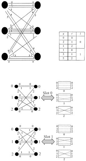
Fig. 10.12 Illustration of time space interleaving principle. Ž 1997 IEEE..
where r g 0, 1, . . . , m y 14 and t g 0, 1, . . . , f y 14 are the quotient and the remainder on dividing a by f, respectively. The mapping gŽa. s Žt, r . from the set 0, 1, . . . , fm y 14 ™ 0, 1, . . . , f y 14 0, 1, . . . , m y 14 is one-to- one and onto, that is,
a s a •´ t s t and r s r .
That is, the color assignment a, or equivalently the assignment pair Žt, r ., of the edge between Ii and Oj indicates that the central module r has been
272 CLOS-NETWORK SWITCHES
assigned to a route from Ii to Oj in the t th time slot of every cycle. Adopting the convention in TDMA system, each cycle will be called a frame, and the period f the frame size. As illustrated by the example shown in Figure 10.12, where m s 3 and f s 2, the decomposition of the edge coloring into assignment pairs guarantees that route assignments are either space-interleaved or time-interleaved. Thus, the relation Ž10.7. will be called the time space interlea®ing principle.
10.5.1Homogeneous Capacity and Route Assignment
For uniform traffic, where the distribution of traffic loading between input modules and output modules is homogeneous, the fm edges of each node can be evenly divided into k groups, where k is the total number of input or output modules. Each group contains g s fmrk edges between any input output pair, where the frame size f should be chosen to make the group size g an integer. The edges of this capacity graph can be easily colored by the Latin square given in Table 10.1, where each Ai , 0 F i F k y 1, represents a set of distinct colors, e.g.,
A0 s 0, 1, . . . , g y 14 , A1 s g , g q 1, . . . , 2 g y 14 , . . .
Aky1 s Ž k y 1. g , Ž k y 1. g q 1, . . . , kg y 14
Since each number in the set 0, 1, . . . , fm y 14 appears only once in any row or column in the table, it is a legitimate edge coloring of the capacity graph. The assignment a s Žt, r . of an edge between the Ii Oj pair indicates that the central module r will connect input module i to output module j in the t th slot of every frame. As an example, for m s 3 and k s 2, we can choose
f s 2 and thus g s 3. Then, the groups |
of colors are A0 s 0, 1, 24 and |
A1 s 3, 4, 54, respectively. The procedure |
described above is illustrated in |
Table 10.2, and the correspondence between the route assignments and the connection patterns in the middle stage is shown in Figure 10.13.
In the above example, since the number of central modules Žm. is greater than the number of input modules Žk., it is possible that more than one central module is assigned to some input output pair in one time slot. In the case that m k, there are not enough central modules for all input output
TABLE 10.1 Latin Square Assignment
|
O0 |
O1 |
O2 |
|
Oky1 |
||
I0 |
A0 |
A1 |
A2 |
|
Aky1 |
||
I |
A |
k.y1 |
A |
A |
|
A |
k.y2 |
.1 |
|
. 0 |
.1 |
|
|
||
. |
|
. |
. |
. |
|
|
. |
. |
|
. |
. |
. |
|
|
. |
Iky1 |
A1 |
A2 |
A3 |
|
A0 |
||

|
|
|
|
|
|
|
THE PATH SWITCH |
273 |
|
||
TABLE 10.2 Route Assignment by Latin Square for Uniform Traffic |
|
|
|
|
|||||||
|
|
|
|
|
|
|
|
|
|
|
|
|
|
|
|
Color |
|
|
|
|
|
|
|
Color |
O0 |
O1 |
|
a s rf q t |
0 |
1 |
2 |
3 |
4 |
5 |
|
|
|
|
|
Central module |
|
|
|
|
|
|
|
I0 |
0, 1, 2 |
3, 4, 5 q r s arf |
0 |
0 |
1 |
1 |
2 |
2 |
|
||
|
|
|
|
Time slot |
|
|
|
|
|
|
|
I1 |
3, 4, 5 |
0, 1, 2 |
|
y s a mod f |
0 |
1 |
0 |
1 |
0 |
1 |
|
|
|
|
|
|
|
||||||
Latin square: edge coloring |
Transformation from color assignment into time space pair |
||||||||||
|
|
|
y |
|
|
|
|
|
|
|
|
Central-module assignment
Central |
|
|
Module |
O0 |
O1 |
I0 |
0, 1 |
2 |
I1 |
2 |
0, 1 |
|
|
|
Time slot 0
Central |
|
|
Module |
O0 |
O1 |
I0 |
0 |
1, 2 |
I1 |
1, 2 |
0 |
|
|
|
Time slot 1
Fig. 10.13 Route scheduling in the middle stage for uniform traffic. Ž 1997 IEEE..
274 CLOS-NETWORK SWITCHES
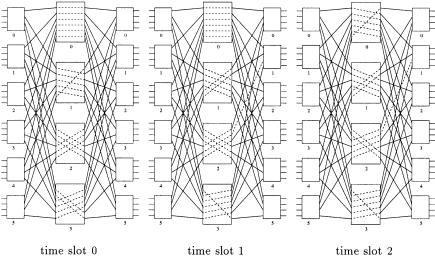
Fig. 10.14 Route scheduling in central modules for the second example of uniform traffic. Ž 1997 IEEE..
pairs in one time slot assignment. Nevertheless, the total number of central modules assigned to every input output pair within a frame should be the same for uniform input traffic to fulfill the capacity requirement, and that number is equal to g s fmrk. This point is illustrated in the following example. For m s 4 and k s 6, we choose f s 3 and g s 2. The same method will result in the connection patterns shown in Figure 10.14. It is easy to verify that the number of central modules Žpaths, edges. assigned for each input output pair is equal to g s 2 per f s 3 slots.
10.5.2Heterogeneous Capacity Assignment
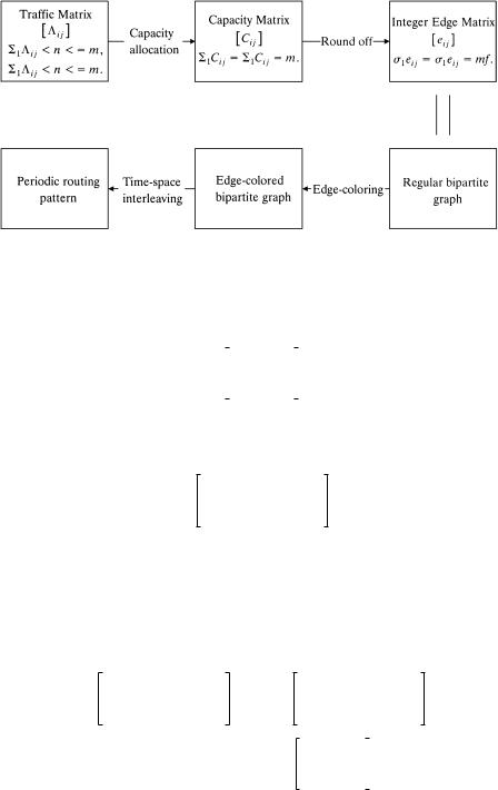
The capacity assignment in a cross-path switch is virtual-path-based. It depends on the traffic load on each virtual path to allocate the capacity and determine the route assignment. The Latin square offers a legitimate capacity assignment with homogeneous traffic, but it may no longer be effective with heterogeneous traffic Žnonuniformly distributed traffic load over the virtual paths.. A more general assignment method is therefore introduced, and the procedure is illustrated in Figure 10.15. The assignment procedure has four steps, each of which will be explained along with an example in the following sub-subsections.
10.5.2.1 Virtual Path Capacity Allocation (VPCA) This step is to allocate capacity to each virtual path based on the traffic loads. It can be formulated as an optimization problem with some traffic modeling.
THE PATH SWITCH |
275 |
Fig. 10.15 Procedure of capacity and route assignment.
Consider the cross-path switch with parameters n s 3, k s 3, and m s 4. Suppose the traffic matrix is given by
T s |
1 |
1 |
1 |
, |
Ž10.8. |
2 |
1 |
0 |
|||
|
0 |
1 |
1 |
|
|
and the capacity assignment matrix calculated by the minimization of inputstage delay with MrDr1 model is
1.34 |
1.28 |
1.38 |
Ž10.9. |
C s 2.66 |
1.34 |
0 . |
01.38 2.62
10.5.2.2The Roundoff Procedure Some elements in the resulting capacity matrix may be nonintegers. When they are rounded to the integers required in the route assignment, roundoff error arises. The concept of frame size is used to reduce the roundoff error. Each element in the capacity matrix is multiplied by the frame size; then the capacity per slot is translated into capacity per frame. After that, we round the matrix into an integer matrix:
1.341.28 1.38
Cs 2.66 |
1.34 |
0 |
0 |
1.38 |
2.62 |
Ž fs3 . |
|
|
4.02 |
|
3.84 |
4.14 |
|||||
|
|
7.98 |
|
3.82 |
0 |
||||||
|
|
|
|
|
|||||||
|
6 |
|
|||||||||
|
|
|
|
|
|
0 |
|
4.14 |
7.86 |
||
rounding |
|
|
4 |
4 |
4 |
|
|
s E. |
|||
|
|
|
|||||||||
|
|
8 |
4 |
0 |
|
|
|||||
|
|
|
|
||||||||
|
6 |
|
|
||||||||
|
|
|
|
|
|
0 |
4 |
8 |
|
|
|
Ž10.10.
276 CLOS-NETWORK SWITCHES
The roundoff error is inversely proportional to f. Thus, the error can be arbitrary small if the frame size is sufficiently large. However, since the amount of routing information stored in the memory is linearly proportional to f, the frame size is limited by the access speed and the memory space of input modules. In practice, the choice of frame size f is a compromise between the roundoff error and the memory requirement. In general,
|
|
e0, 0 |
e0, 1 |
|
e0, ky1 |
|
|
|
|
|
e1 , 0 |
e1, 1 |
|
e1, ky1 |
|
|
|
E s |
. |
. |
. . |
|
. |
|
f f C, |
|
. |
. |
. |
. |
|
||||
|
. |
. |
|
. |
|
|
||
|
|
eky1 , 0 |
eky1 , 1 |
|
eky1 , ky1 |
|
|
|
and |
|
|
|
|
|
|
|
|
|
|
|
Ý ei j s Ý ei j |
s fm. |
|
Ž10.11. |
||
ji
In the above matrix E, each element ei j represents the number of the edges between the input module i and output module j in the k k capacity graph, in which each node has degree fm.
10.5.2.3 Edge Coloring As mentioned previously, this capacity graph can be colored by fm colors, and each color represents one distinct time space slot based on the time space interleaving principle Ž10.7.. Coloring can be found by complete matching, which is repeated recursively to reduce the degree of every node one by one. One general method to search for a complete matching is the so-called Hungarian algorithm or alternating-path
algorithm w9, 12x. It is a sequential algorithm |
with worst time complexity |
OŽk 2 ., or totally OŽ fm k 2 . because there are |
fm matchings. If each of fm |
Fig. 10.16 Route scheduling example Žheterogeneous traffic.. Ž 1997 IEEE..
REFERENCES 277
and k is a power of two, an efficient parallel algorithm proposed in w7x for conflict-free route scheduling in a three-stage Clos network with time complexity of OŽlog2 Ž fmk.. can be used. Through the time space interleaving, the middle-stage routing pattern in Figure 10.16 is obtained.
REFERENCES
1.H. J. Chao and J.-S. Park, ‘‘Centralized contention resolution schemes for a large-capacity optical ATM switch,’’ Proc. IEEE ATM Workshop-97, Fairfax, VA, May 1998.
2.H. J. Chao , ‘‘Saturn: a terabit packet switch using dual round-robin,’’ IEEE Commun. Mag., vol. 38, no. 12, pp.78 84, Dec. 2000.
3.K. Y. Eng and A. S. Acampora, ‘‘Fundamental conditions governing TDM switching assignments in terrestrial and satellite networks,’’ IEEE Trans. Com- mun., vol. 35, pp. 755 761, Jul. 1987.
4.K. Y. Eng, M. J. Karol, and Y.-S. Yeh, ‘‘A growable packet ŽATM. switch architecture: design principles and applications,’’ IEEE Trans. Commun., vol. 40, no. 2, pp. 423 430, Feb. 1992.
5.M. J. Karol and C.-L. I, ‘‘Performance analysis of a growable architecture for
broadband packet ŽATM. switching,’’ Proc. IEEE GLOBECOM ’89, pp. 1173 1180, Nov. 1989.
6.C. H. Lam, ‘‘Virtual path traffic management of cross-path switch,’’ Ph.D. dissertation, Chinese University of Hong Kong, Jul. 1997.
7.T. T. Lee and S. Y. Liew, ‘‘Parallel algorithm for Benes networks,’’ Proc. IEEE INFOCOM ’96, Mar. 1996.
8.T. T. Lee and C. H. Lam, ‘‘Path switching A quasi-static routing scheme for large-scale ATM packet switches,’’ IEEE J. Select. Areas Commun., vol. 15, no. 5, pp. 914 924, Jun. 1997.
9.F. T. Leighton, Introduction to Parallel Algorithms and Architectures: Arrays Trees Hypercubes, Morgan Kaufmann, 1992.
10.F. M. Chiussi, J. G. Kneuer, and V. P. Kumar, ‘‘Low-cost scalable switching solutions for broadband networking: the ATLANTA architecture and chipset,’’ IEEE Commun. Mag., pp. 44 53, Dec. 1997.
11.N. Mckeown, ‘‘The iSLIP scheduling algorithm for input-queue Switches,’’ IEEE Trans. Networking, vol. 7, no. 2, pp. 188 200, Apr. 1999.
12.R. J. McEliece, R. B. Ash, and C. Ash, Introduction to Discrete Mathematics, McGraw-Hill, 1989.
13.N. Mckeown, ‘‘Scheduling algorithm for input-queued cell switches,’’ Ph.D. Thesis, University of California at Berkeley, 1995.
14.E. Oki, Z. Jing, R. Rojas-Cessa, and H. J. Chao, ‘‘Concurrent round-robin dispatching scheme in a Clos-network switch,’’ IEEE ICC 2001, pp. 107 112, Helsinki, Finland, Jun. 2001.
15.R. J. Wilson, Introduction to Graph Theory, Academic Press, New York, 1972.
16.Y.-S. Yeh, M. G. Hluchyj, and A. S. Acampora, ‘‘The knockout switch: a simple, modular architecture for high-performance packet switching,’’ IEEE J. Select. Areas Commun., vol. 5, no. 8, pp. 1274 1283, Oct. 1987.