

AutoCAD 2005 For Dummies (2004)
.pdf310 Part IV: Share and Share Alike
child drawing can have lots of parent drawings that refer to it — apparently it’s the commune version of family relations. If you find such relationships odd, you can, like the AutoCAD online help system, refer to the parent drawing as the host drawing. I prefer the terms parent and child, in part because they’re easily extendable to describing more complex hierarchies, such as a parent drawing, which xrefs a child drawing, which in turn xrefs a grandchild drawing.
Xrefs have a big advantage over blocks: If you change a child drawing, AutoCAD automatically loads the change into all the parent drawings that reference the child drawing.
AutoCAD loads all xrefs into the parent drawing each time the parent drawing is opened. If the child drawing has been changed, AutoCAD automatically incorporates those changes into the parent drawing.
When you open a drawing containing xrefs, AutoCAD 2004 displays a little symbol (which looks like papers with a binder clip) on the right end of the status bar. This symbol alerts you to the fact that some of the things you see in the drawing are actually parts of other, xrefed drawings. If an xref changes while you have the parent drawing open (because you or someone else opens and saves the child drawing), the status bar xref symbol displays an External Reference Files Have Changed balloon notification. (If you want to change whether the notifications appear and how often AutoCAD checks for changes, look up XREFNOTIFY and XNOTIFYTIME in the online help.) You can use the Reload option in the Xref Manager dialog box to show the updated xrefs. See the “Managing xrefs” section later in this chapter for details.
Another advantage of xrefs over blocks is that their contents aren’t stored in your drawing even once. The disk storage space taken up by the original drawing (that is, the xref) isn’t duplicated, no matter how many parent drawings reference it. This characteristic makes xrefs much more efficient than blocks for larger drawings that are reused several times.
But you can always buy more hard disk space, so the storage issue isn’t crucial. The key benefit of xrefs is that they enable you to organize your drawings in a modular way so that changes you make to a single drawing file automatically “ripple through” all the parent drawings to which it’s xrefed. This benefit is even greater on larger projects involving multiple drafters, each of whose work may be incorporated in part or in whole in the work of others.
The automatic update feature of xrefs is a big advantage only if you’re organized about how you use xrefs. Suppose that an architect creates a plan drawing showing a building’s walls and other major features that are common to the architectural, structural, plumbing, and electrical plan drawings. The architect then tells the structural, plumbing, and electrical drafters to xref this background plan into their drawings, so that everyone is working from a consistent and reusable set of common plan elements. If the architect decides to revise
Chapter 13: Playing Blocks and Rasteroids 311
the wall locations and updates the xrefed drawing, everyone will see the current wall configuration and be able to change their drawings. But if the architect absent-mindedly adds architecture-specific objects, such as toilets and furniture, to the xrefed drawing, or shifts all the objects with respect to 0,0, everyone else will have problems. If different people in your office share xrefs, create a protocol for who is allowed to modify which file when, and what communication needs to take place after a shared xref is modified.
Becoming attached to your xrefs
Attaching an external reference is similar to inserting a block, and almost as easy. Just use the following steps:
1.Set an appropriate layer current, as described in Chapter 4.
I recommend that you insert xrefs on a separate layer from all other objects. Note that if you freeze the layer an xref is inserted on, the entire xref disappears. (This behavior can be either a handy trick or a nasty surprise.)
2.Choose Insert Xref Manager from the menu bar to start the XRef command.
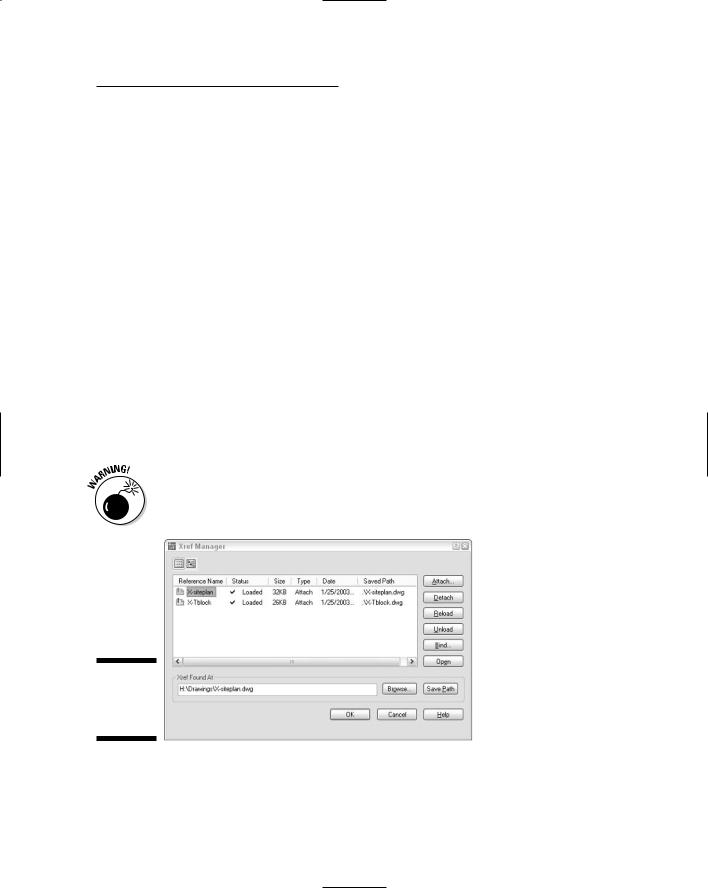
The Xref Manager dialog box appears (see Figure 13-7).
Don’t choose Insert External Reference. This menu choice jumps ahead to Step 4, which will be confusing at this point.
Figure 13-7:
The Xref
Manager dialog box.
3.Click Attach.
The Select Reference File dialog box appears.

312 Part IV: Share and Share Alike
4.Browse to find the file you want to attach, select it, and then click Open.
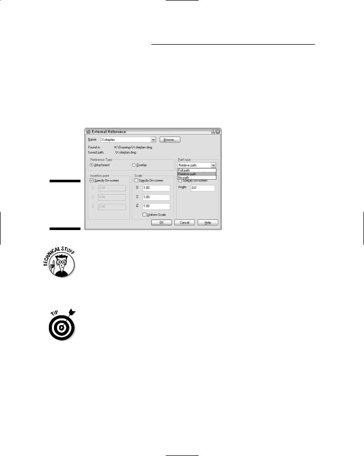
The External Reference dialog box appears.
5.Specify the parameters for the xref in the dialog box.
Parameters include the insertion point, scaling factors, and rotation angle. You can set these parameters in the dialog box or specify them on-screen, just as you can do when inserting a block, as described earlier in this chapter.
You can choose the Attachment or Overlay radio button to tell AutoCAD how to handle the xref. The choice matters only if you create a drawing that uses xrefs, and then your drawing is in turn used as an xref. Attachment is the default choice, and it means that the xrefed file will always be included with your drawing when someone else uses your drawing as an xref. Overlay, the other choice, means that you see the xrefed drawing, but someone who xrefs your drawing won’t see the overlaid file. By choosing Overlay, you can xref in a map, for example, to your drawing of a house, but not have the map show up when someone else xrefs your house drawing. (That person can xref the map, if need be.) I recommend that you use the default Attachment reference type unless you have a specific reason to do otherwise.
The Path Type drop-down list provides more flexibility in how the xref’s path gets stored. See the “Forging an xref path” section later in this chapter for more information. For now, I recommend that you choose
Relative path instead of the default Full path.
6.Click OK.
The externally referenced file appears in your drawing.
Layer-palooza
When you attach or overlay an xref, AutoCAD adds new layers to your current drawing that correspond to the layers in the xrefed DWG file. The new layers are assigned names that combine the drawing name and layer name; for example, if you xref the drawing MYSCREW.DWG, which has the layer names GEOMETRY, TEXT, and so on, the xrefed layers will be named MYSCREW| GEOMETRY, MYSCREW|TEXT, and so on. By creating separate layers corresponding to each layer in the xrefed file, AutoCAD eliminates the potential problem I warned you about with blocks when layers have the same name but different color or linetype in the two drawings.
AutoCAD also creates new linetypes, text styles, dimension styles, and block definitions for each of these items in the xrefed file — for example, MYSCREW|DASHED, MYSCREW|NOTES, MYSCREW|A-DIMS, and MYSCREW|LOGO.
Chapter 13: Playing Blocks and Rasteroids 313
Creating and editing an external reference file
To create a file that you can use as an external reference, just create a drawing and save it (or use the WBLOCK command to create a new DWG from geometry in the current drawing). That’s it. You then can create or open another drawing and create an external reference to the previous one. The xrefed drawing appears in your parent drawing as a single object, like a block insert. In other words, if you click any object in the xref, AutoCAD selects the entire xref. You can measure or object snap to the xrefed geometry, but you can’t modify or delete individual objects in the xref — you open the xref drawing in order to edit its geometry.
AutoCAD 2004’s XOPEN command (Modify Xref and Block Editing Open Reference) provides a quick way to open an xrefed drawing for editing. You just start the command and pick on any object in the xref. Alternatively, you can use the Open button in the Xref Manager dialog box to open one or more xrefs for editing. See the “Managing xrefs” section later in this chapter for more information.
An alternative to opening the xrefed file when you need to edit it is to use the REFEDIT command (Modify Xref and Block Editing Edit Reference In-Place). Look up “REFEDIT” in the AutoCAD online help system.
Forging an xref path
When you attach an xref, AutoCAD by default stores the xref’s full path — that is, the drive letter and sequence of folders and subfolders in which the DWG file resides, along with the filename. This default behavior corresponds to the Full path setting in the Path Type drop-down list. (Figure 13-8 shows the three xref path options.) Full path works fine as long as you never move files on your hard disk or network and never send your DWG files to anyone else — which is to say, it almost never works fine!
At the other end of the path spectrum, the No path option causes AutoCAD not to store any path with the xref attachment — only the filename is stored. This is the easiest and best option if the parent and child drawings reside in the same folder.
If you prefer to organize the DWG files for a particular project in more then one folder, then you’ll appreciate AutoCAD’s Relative path option, shown in Figure 13-8. This option permits xrefing across more complex, hierarchical folder structures, but avoids many of the problems that Full path can cause.
314 Part IV: Share and Share Alike
For example, you may have a parent drawing H:\Project-X\Plans\First floor.dwg that xrefs H:\Project-X\Common\Column grid.dwg. If you choose Relative path, AutoCAD will store the xref path as ..\ Common\Column grid.dwg instead of H:\Project-X\Common\Column grid.dwg. Now if you decide to move the \Project-X folder and its subfolders to a different drive (or send them to someone else who doesn’t have an H: drive), AutoCAD will still be able to find the xrefs.
Figure 13-8:
Chart your path when you attach an xref.
When you use Relative path, you’ll see xref paths that include the special codes . and .. (single and double period). The single period means “this parent drawing’s folder” and the double period means “the folder above this parent drawing’s folder” (in other words, the folder of which the parent drawing’s folder is a subfolder).
You can report on and change xref paths for a set of drawings with the AutoCAD Reference Manager. See Chapter 16 for more information.
If all these path options and periods have got you feeling punchy, you can keep your life simple by always keeping parent and child drawings in the same folder and using the No path option when you attach xrefs.
Managing xrefs
The Xref Manager dialog box includes many more options for managing xrefs after you attach them. Important dialog box options include:
Chapter 13: Playing Blocks and Rasteroids 315
List of external references: You can change between a List and a Tree view of your drawing’s external references just by clicking the appropriate button at the top of the dialog box. You also can resize the columns by dragging the column dividers or re-sort the list by clicking the column header names, just as in other Windows dialog boxes.
Detach: Completely removes the selected reference to the external file from your drawing.
Reload: Causes AutoCAD to reread the selected xrefed DWG file from the disk and update your drawing with its latest contents. This feature is handy when you share xrefs on a network and someone has just made changes to a drawing that you’ve xrefed.
Unload: Makes the selected xref disappear from the on-screen display of your drawing and from any plots you do of it, but retains the pointer and attachment information. Use the Reload button to redisplay an unloaded xref.
Bind: Brings the selected xref into your drawing and makes it a block. You might use this function, for example, to “roll up” a complex set of xrefs into a single archive drawing.
In many offices, binding xrefs without an acceptable reason for doing so is a crime as heinous as exploding blocks indiscriminately. In both cases, you’re eliminating an important data management link. Find out what the policies are in your company. When in doubt, keep yourself out of a bind. And even when you do have a good reason to bind, you generally should do it on a copy of the parent drawing.
Open: Opens one or more xref drawings in separate drawing windows after you close the Xref Manager dialog box. After you edit and save an xref drawing, return to the parent drawing and use the Reload option in the Xref Manager dialog box to show the changes.
None of these options (other than opening and editing the xref) affects the xrefed drawing itself; it continues to exist as a separate DWG file. If you need to delete or move the DWG file that the xref refers to, do it in Windows Explorer.
The fact that the xrefed drawing is a separate file is a potential source of problems when you send your drawing to someone else; that someone else needs all the files that your drawing depends on, or it will be useless to the receiving party. Make sure to include xrefed files in the package with your drawing. See Chapter 16 for a procedure.
AutoCAD (but not AutoCAD LT) includes an additional xref feature called xref clipping. You can use the XCLIP command to clip an externally referenced file so only part of it appears in the parent drawing. AutoCAD LT doesn’t include the XCLIP command, but if you open a drawing containing an xref that was clipped in AutoCAD, the clipped view will be preserved.

316 Part IV: Share and Share Alike
Blocks, Xrefs, and Drawing Organization
Blocks and xrefs are useful for organizing sets of drawings to use and update repeated elements . It’s not always clear, though, when to use blocks and when to use xrefs. Applications for xrefs include
The parts of a title block that are the same on all sheets in a project.
Reference elements that need to appear in multiple drawings (for example, wall outlines, site topography, column grids).
Assemblies that are repeated in one or more drawings, especially if the assemblies are likely to change together (for example, repeated framing assemblies, bathroom layouts, modular furniture layouts).
Pasting up several drawings (for example, details or a couple of plans) onto one plot sheet.
Temporarily attaching a background drawing for reference or tracing.
On the other hand, blocks remain useful in simpler circumstances. Situations in which you might stick with a block are:
Components that aren’t likely to change.
Small components.
A simple assembly that’s used repeatedly, but in only one drawing. (You can easily update a block in one drawing with the REDEFIT command.)
When you want to include attributes (variable text fields) that you can fill in each time you insert a block. Blocks let you include attribute definitions; xrefs don’t.
Everyone in a company or workgroup should aim for consistency in when and how they use blocks and xrefs. Check whether guidelines exist for using blocks and xrefs in your office. If so, follow them; if not, it would be a good idea to develop some guidelines. Chapter 15 discusses how to start such guidelines.
Mastering the Raster
AutoCAD includes another xreflike feature: the ability to attach raster images to drawings. This feature is useful for adding a raster logo to a drawing title block or placing a photographed map or scene behind a drawing. A raster, or bitmapped, image is one that’s stored as a field of tiny points.
Chapter 13: Playing Blocks and Rasteroids 317
Most AutoCAD drawings are vector images. A vector image is an image defined by storing geometrical definitions of a bunch of objects. Typical objects include a line, defined by its two endpoints, and a circle, defined by its center point and radius. Vector-based images are typically smaller (in terms of the disk space they occupy) and more flexible than raster images, but also are less capable of displaying visually rich images such as photographs.
Raster images often come from digital cameras or other programs, such as Photoshop. Raster images also can come into the computer from some kind of scanner that imports a blueline print, photograph, or other image.
Whether you’re doing your scanning yourself or having a service bureau do it for you, you need to know that AutoCAD handles most of the popular image file formats including the Windows BMP format, the popular Web graphics formats GIF and JPEG, the popular PCX and TIFF formats, as well as DIB, FLC, FLI, GP4, MIL, PNG, RLE, RST, and TGA.
Here are three scenarios to incorporate raster images in your drawing:
Small stuff: You can add logos, special symbols, and other small images that you have in raster files.
Photographs and maps: You can add photographs (such as a future building site) and maps (for example, showing the project location).
Vectorization: To convert a raster image into a vector drawing by tracing lines in the raster image, you can attach the raster image in your drawing, trace the needed lines by using AutoCAD commands, then detach the raster image. (This procedure is okay for a simple raster image; add-on software is available, from Autodesk and others, to support automatic or semiautomatic vectorization of more complex images.)
Using raster images is much like using external references. The raster image isn’t stored with your drawing file; a reference to the raster image file is established from within your drawing, like an xref. You can clip the image and control its size, brightness, contrast, fade, and transparency. These controls fine-tune the appearance of the raster image on-screen and on a plot.
When you attach raster images, you have to make sure that you send the raster files along when you send your drawing to someone else.
AutoCAD LT can open, view, and plot drawings containing attached raster images, but LT can’t do the attaching. Raster masters require full AutoCAD.

318 Part IV: Share and Share Alike
Attaching an image
Follow these steps to bring a raster image into AutoCAD:
1.Choose Insert Image Manager from the menu bar or type IMage at the command line to start the IMage command.
The Image Manager dialog box appears (see Figure 13-9).
Figure 13-9:
The Image Manager dialog box.
2.Click the Attach button.
The Select Image File dialog box appears.
3.Browse to find the file you want to attach, select it, then click Open.
The Image dialog box appears.
Click the Details button in the Image dialog box to see more information about the resolution and image size of the image you’re attaching.
4.Specify the parameters for the attached image in the dialog box.
Parameters include the insertion point, scale factor, and rotation angle. You can set these parameters in the dialog box or specify them on-screen, similar to what you can do with blocks and external references, as described earlier in this chapter. Use the quick dialog box help (click the question mark in the dialog box’s title bar and then click the area in the dialog box for which you want help) or click the dialog box’s Help button to find out more about specific options.
The AutoCAD 2005 IMage command includes the same Full path, Relative path, and No path options that debuted for xrefs in AutoCAD 2004. (See “Forging an xref path” earlier in this chapter.)
Chapter 13: Playing Blocks and Rasteroids 319
5.Click OK.
The image appears in your drawing.
6.If you need to ensure that the raster image floats behind other objects in the drawing, select the raster image, right-click, choose Draw Order, and then choose Send to Back.
The DRaworder command provides additional options for which objects appear on top of which other objects. If you need this kind of flexibility, look up “DRAWORDER command” in the AutoCAD online help system.
Managing images
You manage the images in your drawing with the Image Manager dialog box. It includes virtually the same options as the External References dialog box. You can view a list of image files that appear in the current drawing, detach (remove) image references, and unload and reload images when needed. You can’t bind an image to your drawing; it always remains an external file.
You can clip images so that only part of the image is displayed in your drawing. Choose Modify Clip Image and follow the prompts to clip the image. You can have multiple overlapping or distinct pieces of any number of images in your drawing, and only the parts you need are loaded into memory when you have your drawing open.
Raster image files often are larger than DWG files of corresponding complexity; raster file size can affect performance within AutoCAD, because the raster file loads into memory when you are working on your drawing. Some workarounds speed up operations:
Attach raster images late in the production process.
Create a lower-resolution version of the raster file, just large enough to create the desired effect in your drawing.
Use the Unload button in the Image Manager dialog box to temporarily disable an image without losing the attachment information.
In addition, raster files can increase the time that AutoCAD takes to generate plots (and the plot file sizes) dramatically. Before you settle on using large raster files in your AutoCAD drawing, do some testing on zooming, editing, and plotting.