

AutoCAD 2005 For Dummies (2004)
.pdf230 Part III: If Drawings Could Talk
Dimension updates when you change the object
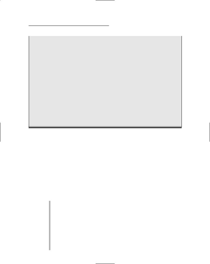
Figure 10-1:
Changing objects automatically updates dimensions.
Original dimension
You may be able to avoid getting too deeply into the details of dimensioning just by copying dimension styles from existing drawings in your office. (I show you how later in this chapter.) This may also be a good time to get some advice and coaching from the AutoCAD geek in the cubicle across from yours.
You add dimensions to a drawing after you’ve drawn at least some of the geometry; otherwise, you won’t have much to dimension! Your dimensioning and overall drafting efficiency improve if you add dimensions in batches, rather than draw a line, draw a dimension, draw another line, draw another dimension. . . .
Why dimensions in CAD?
You may think that CAD would have rendered text dimensions obsolete. After all, you comply with all my suggestions about using AutoCAD precision techniques when you draw and edit, and you’re careful to draw each object at its true size, right? The contractor or machinist can just use AutoCAD to query distances and angles in the CAD DWG file, right? Sorry, but no (to the
last question, anyway). Here are a few reasons why the traditional dimensioning that CAD drafting has inherited from manual drafting is likely to be around for a while:
Some people need to or want to use paper drawings when they build something. We’re still some time away from the day when
Chapter 10: Entering New Dimensions 231
contractors haul computers around in their tool belts (never mind mousing around a drawing while hanging from scaffolding).
In many industries, paper drawings still rule legally. Your company may supply both plotted drawings and DWG files to clients, but your contracts probably specify that the plotted drawings govern in the case of any discrepancy. The contracts probably also warn against relying on any distances that the recipient of the drawings measures — using measuring commands in the CAD DWG file or a scale on the plotted drawing. The text dimensions are supposed to supply all the dimensional information that’s needed to construct the object.
Dimensions sometimes carry additional information besides the basic length or
angle. For example, dimension text can indicate the allowable construction tolerances or show that a particular distance is typical of similar situations elsewhere on the drawing.
Even conscientious CAD drafters rarely draw every object its true size. Drafters sometimes exaggerate distances for graphical clarity. For example, they might draw a small object larger than its true size so that it shows up clearly on a scaled plot. In addition, drafters sometimes settle for approximate distances because time pressures (especially late in a project) make it difficult to be completely accurate.
So remember the old rule of drafting prowess: “It’s not the size of the drawn object that matters, but the dimensions that are on it.”
Discovering New Dimensions
Before digging into the techniques that you use to create dimension styles and dimensions, I review some AutoCAD dimensioning terminology. If you’re already familiar with CAD dimensioning lingo, just skim this section and look at the figures in it. Otherwise, read on.
Anatomy of a dimension
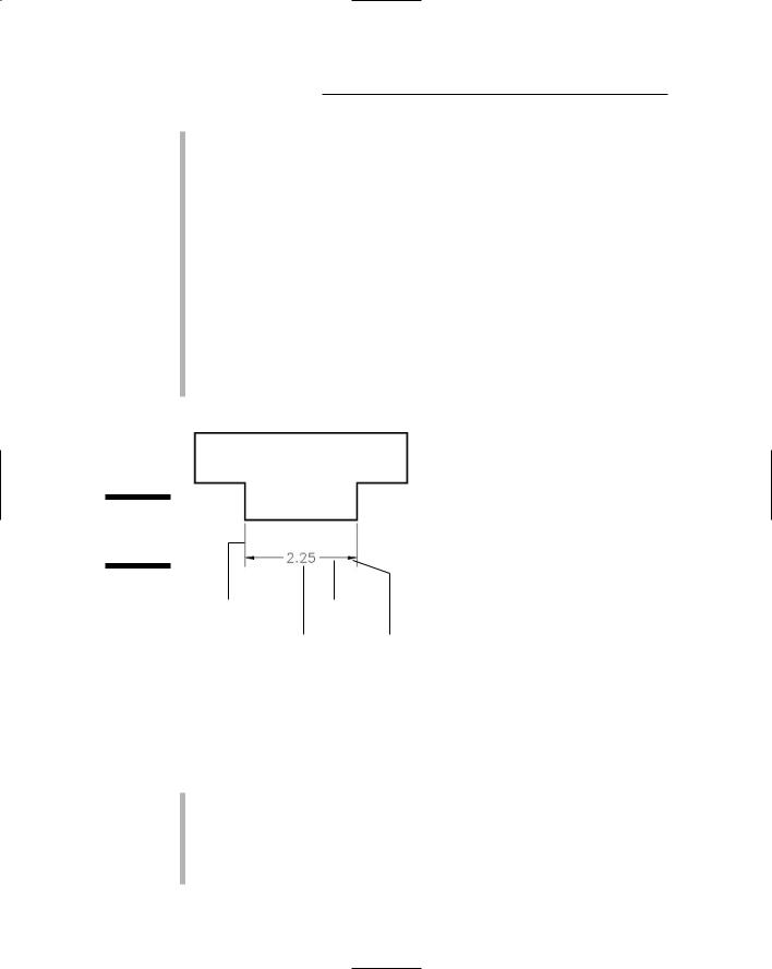
AutoCAD uses the names shown in Figure 10-2 and described in the following list to refer to the parts of each dimension:
Dimension text: Dimension text usually is the number that indicates the actual distance or angle. Dimension text can also include other text information in addition to or instead of the number. For example, you can add a suffix such as TYP. to indicate that a dimension is typical of several similar configurations, or you can insert a description such as
See Detail 3/A2.
Dimension lines: The dimension lines go from the dimension text outward (parallel to the direction of the object being measured), to indicate the extent of the dimensioned length. AutoCAD’s default dimension style settings center the dimension text vertically and horizontally on the dimension lines (see Figure 10-2), but you can change those settings to
232 Part III: If Drawings Could Talk
cause the text to appear in a different location — riding above an unbroken dimension line as shown in Figure 10-1, for example. See the section “Adjusting style settings,” later in this chapter, for instructions.
Dimension arrowheads: The dimension arrowheads appear at the ends of the dimension lines and clarify the extent of the dimensioned length. AutoCAD’s default arrowhead style is the closed, filled type shown in Figure 10-2, but you can choose other symbols, such as tick marks, to indicate the ends of the dimension lines. (Don’t get ticked off, but AutoCAD calls the line ending an arrowhead even when, as in the case of a tick mark, it doesn’t look like an arrow.)
Extension lines: The extension lines extend outward from the extension line origin points that you select (usually by snapping to points on an object) to the dimension lines. By drafting convention, a small gap usually exists between the extension line origin points and the beginning of the extension lines. The extension lines usually extend just beyond where they meet the dimension lines.
Figure 10-2:
The parts of a dimension.
Extension line |
Dimension line |
origin point |
|
|
Dimension text Arrowhead |
A field guide to dimensions
AutoCAD provides several types of dimensions and commands for drawing them. Figure 10-3 shows the most common types, and the following list describes them:
Linear dimensions: A linear dimension measures the linear extent of an object or the linear distance between objects. Most linear dimensions are either horizontal or vertical, but you can draw dimensions that are rotated to other angles, too. An aligned dimension is similar to a linear dimension, but the dimension line tilts to the same angle as a line drawn through the origin points of its extension lines.
Chapter 10: Entering New Dimensions 233
Radial dimensions: A radius dimension calls out the radius of a circle or arc, and a diameter dimension calls out the diameter of a circle or arc. You can position the dimension text inside or outside the curve, as shown in Figure 10-3. If you position the text outside the curve, AutoCAD by default draws a little cross at the center of the circle or arc.
Angular dimensions: An angular dimension calls out the angular measurement between two lines, the two endpoints of an arc, or two points on a circle. The dimension line appears as an arc that indicates the sweep of the measured angle.
Vertical linear dimension |
|
Aligned dimension |
Radius dimension |
Figure 10-3:
Common types of dimensions.
Angular dimension |
Diameter dimension |
Horizontal linear dimension |
|
Other types of AutoCAD dimensions include ordinate, tolerance, center mark, and leader dimensions. See the “Pointy-Headed Leaders” section at the end of this chapter for instructions on how to draw leaders. Look up “dimensions, creating” on the Index tab in the AutoCAD online help system for more information about other kinds of dimensions.
Dimension associativity
By default, AutoCAD groups all the parts of each dimension — the extension lines, dimension lines, arrowheads, and text — into a special associative dimension object. Associative means two things:
The different parts of the dimension function as a single object. When you click any part of the dimension, AutoCAD selects all of its parts.
The dimension is connected with the points on the object that you specified when you drew the dimension. If you change the size of the object
234 Part III: If Drawings Could Talk
(for example, stretch a line), the dimension updates appropriately — the lines and arrows move, and the text changes to reflect the line’s new size.
I call dimensions with both of these characteristics geometry-driven associative dimensions, because the geometry “drives” the location of the parts of the dimension and what the text says.
For historical reasons, AutoCAD also is capable of creating dimensions that possess just the first type of associativity — that is, the dimension functions as a single, grouped object but isn’t directly connected with the object whose size it shows. Autodesk now calls these kinds of dimensions nonassociative, which is pretty confusing to AutoCAD veterans, because AutoCAD used to call them associative! AutoCAD also is capable of creating dimensions that possess no type of associativity at all — no grouping of the bits and pieces and no connection to the dimensioned object. Autodesk now calls these exploded dimensions, but before AutoCAD 2002, they were called nonassociative!
I mention the conflicting use of associative and nonassociative in case you find yourself discussing dimensions with AutoCAD veterans, most of whom will use the terms in their older sense. To avoid confusion, I always use the term geometry-driven associative dimensions (or simply geometry-driven dimensions) in this book to refer to dimensions that possess both types of associativity. For more information about how to determine which kind of dimension AutoCAD draws, see “Controlling and editing dimension associativity,” later in this chapter.
Pulling out your dimension tools
The AutoCAD Dimension menu provides access to dimensioning commands. If you find yourself adding dimensions in batches, the Dimension toolbar is more efficient because it makes the dimensioning commands more accessible. You toggle the Dimension toolbar off and on by right-clicking any AutoCAD toolbar icon and choosing Dimension from the cursor menu. As with other toolbars, you can move the Dimension toolbar to a different location on the screen or dock it on any margin of the drawing area.
All dimensioning commands have long command names (such as DIMLINEAR and DIMRADIUS) and corresponding shortened abbreviations (DLI and DRA) that you can type at the command prompt. If you do lots of dimensioning and don’t want to toggle the Dimension toolbar on and off repeatedly, memorize the abbreviated forms of the dimension commands that you use frequently. You’ll find a list of the long command names on the Contents tab in the AutoCAD online help system. Choose Command Reference Commands
D Commands. The short names are the first, fourth, and fifth letters of the long names. (In other words, take the first five letters of the long name and remove IM.)

Chapter 10: Entering New Dimensions 235
Doing Dimensions with Style(s)
Creating a usable dimension style that gives you the dimension look you want is the biggest challenge in using AutoCAD’s dimensioning features. Each drawing contains its own dimension styles, so changes you make to a dimension style in one drawing affect only that drawing. However, after you get the dimension styles right in a drawing, you can use it as a template or starting point for later drawings.
A dimension style is a collection of drawing settings called dimension variables, which are a special class of the system variables that I introduce in Chapter 2.
If you want to see a list of the dimension variable names and look up what each variable controls, see Contents Command Reference System Variables
D System Variables in the AutoCAD online help system. All the system variables that begin with DIM are dimension variables.
AutoCAD users, like all computer nerds, like to shorten names. You may hear them refer to dimstyles and dimvars instead of dimension styles and dimension variables. You can tell them that doing so makes you think of them as dimwits — which is actually an honorable title at Autodesk, as I mention earlier in this chapter.
Borrowing existing dimension styles
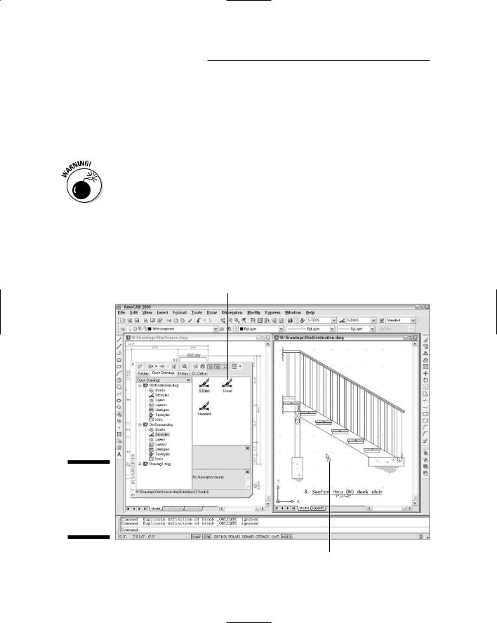
If you’re lucky enough to work in an office where someone has set up dimension styles that are appropriate for your industry and project, you can skip the pain and strain of creating your own dimension styles. If the ready-made dimension style that you need lives in another drawing, you can use the DesignCenter palette to copy it into your drawing, as described in the following steps:
1.Open the drawing that contains the dimension style you want to copy (the source drawing).
2.Open the drawing to which you want to copy the dimension style (the destination drawing).
If you already had both drawings open, make sure that you can see the destination drawing. If you can’t, choose the Window menu and then choose the destination drawing in order to bring it to the foreground.
3.Click the AutoCAD DesignCenter button on the Standard toolbar.
The DesignCenter palette appears. (Chapter 4 describes this palette in detail.)
4.In the DesignCenter palette, click the Open Drawings tab.
DesignCenter’s navigation pane displays a list of drawings that you currently have open in AutoCAD.
236 Part III: If Drawings Could Talk
5.In the left pane of the DesignCenter palette, click the plus sign next to the name of the drawing that you opened in Step 1.
A list of copyable objects, including Dimstyles, appears.
6.Click and drag the desired dimension style from the right pane of the DesignCenter palette into the window containing the drawing that you opened in Step 2, as shown in Figure 10-4.
If the name of the dimension style that you copy duplicates the name of an existing dimension style in the destination drawing, AutoCAD refuses to overwrite the existing dimension style. In that case, you must first rename the existing dimension style in the destination drawing by using the information in the following section, “Creating and managing dimension styles.”
7.Change the Use Overall Scale Of factor on the Fit tab of the Modify Dimension Style dialog box so that it matches the drawing scale factor of the current drawing.
See Chapter 3 for detailed instructions.
Drag from source drawing's Dimstyles in AutoCAD DesignCenter
Figure 10-4:
Copying a dimension style from one drawing to another.
Drop in destination drawing
Chapter 10: Entering New Dimensions 237
If you want a dimension style to be available in new drawings, copy the style to a template drawing and use that template to create your new drawings. See Chapter 3 for more information about template drawings.
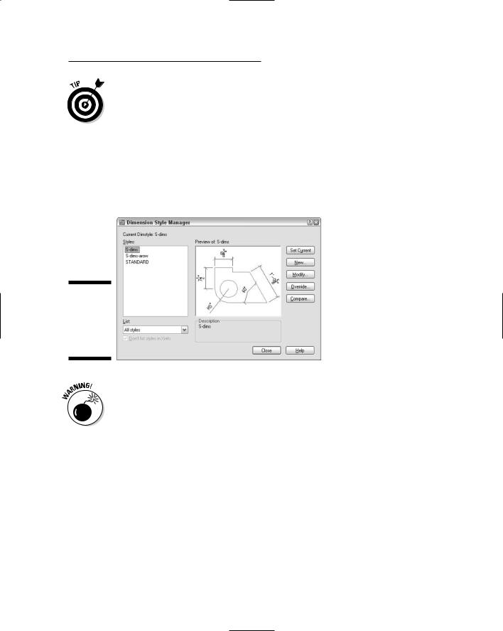
Creating and managing dimension styles
If you do need to create your own dimension styles, or you want to tweak ones that you copied from another drawing, you use the Dimension Style Manager dialog box, shown in Figure 10-5.
Figure 10-5:
Yet another manager, this one for dimension styles.
Every drawing comes with a default dimension style named Standard (for nonmetric drawings) or ISO-25 (for metric drawings). Although you can use and modify the Standard or ISO-25 style, I suggest that you leave it as is and create your own dimension style(s) for the settings that are appropriate to your work. This approach ensures that you can use the default style as a reference. More important, it avoids a potential naming conflict that can change the way your dimensions look if the current drawing gets inserted into another drawing. (Chapter 13 describes this potential conflict.)
The following steps describe how to create your own dimension style(s):
1.Choose Format Dimension Style from the menu bar, or click the
Dimension Style Manager button on the Styles toolbar.
The Dimension Style Manager dialog box appears.
2.In the Styles list, select the existing dimension style whose settings you want to use as the starting point for the settings of your new style.
For example, select the default dimension style named Standard or ISO-25.

238 Part III: If Drawings Could Talk
3.Click the New button to create a new dimension style that’s a copy of the existing style.
The Create New Dimension Style dialog box appears.
4.Enter a New Style Name and click Continue.
The New Dimension Style dialog box appears, which is the same as the Modify Dimension Style dialog box shown in Figure 10-6.
5.Modify dimension settings on any of the six tabs in the New Dimension Style dialog box.
See the descriptions of these settings in the next section of this chapter. In particular, be sure to set the Use Overall Scale Of factor on the Fit tab to set the drawing scale factor.
6.Click OK to close the New Dimension Style dialog box.
The Dimension Style Manager dialog box reappears.
7.Select your new dimension style from the Styles list, and then click Set Current.
Your new dimension style becomes the current dimension style that AutoCAD uses for future dimensions in this drawing.
8.Click Close.
The Dimension Style Manager dialog box closes.
9.Draw some dimensions to test your new dimension style.
Avoid changing existing dimension styles that you didn’t create, unless you know for sure what they’re used for. When you change a dimension style setting, all dimensions that use that style change to reflect the revised setting. Thus, one small dimension variable setting change can affect a large number of existing dimensions! When in doubt, ask the dimension style’s creator what the dimension style is for and what the consequences of changing it are. If that’s not possible, instead of modifying an existing dimension style, create a new style by copying the existing one, and then modify the new one.
A further variation on the already baroque dimension style picture is that you can create dimension secondary styles (also called substyles or style families) — variations of a main style that affect only a particular type of dimension, such as radial or angular. You probably want to avoid this additional complication if you can, but if you open the Dimension Style Manager dialog box and see names of dimension types indented beneath the main dimension style names, be aware that you’re dealing with secondary styles. Look up “dimension styles, secondary styles” on the Index tab in the AutoCAD online help system for more information.

Chapter 10: Entering New Dimensions 239
Adjusting style settings
After you click New or Modify in the Dimension Style Manager dialog box, AutoCAD displays a tabbed New/Modify Dimension Style subdialog box with a mind-boggling — and potentially drawing-boggling, if you’re not careful — array of settings. Figure 10-6 shows the settings on the first tab, which I’ve modified from the AutoCAD defaults to conform to one office’s drafting standards.
Figure 10-6:
Modifying dimension settings.
Fortunately, the dimension preview that appears on all tabs — as well as on the main Dimension Style Manager dialog box — immediately shows the results of most setting changes. With the dimension preview and some trial-and-error changing of settings, you usually can home in on an acceptable group of settings. For more information, use the dialog box help: Click the question mark button on the title bar and then click the setting that you want to know more about.
Before you start messing with dimension style settings, it’s important to know what you want your dimensions to look like when they’re plotted. If you’re not sure how it’s done in your industry, ask others in your office or profession or look at a plotted drawing that someone in the know represents as being a good example.
The following sections introduce you to the more important New/Modify Dimension Style tabs and highlight useful settings. Note that whenever you specify a distance or length setting, you should enter the desired plotted size. AutoCAD scales all these numbers by the overall scale factor that you enter on the Fit tab.