

AutoCAD 2005 For Dummies (2004)
.pdf290 Part III: If Drawings Could Talk
Usually, you’ll choose to plot Layout in paper space. For model space, the choice depends on whether the drawing was set up properly and what you want to plot. If you set limits properly, as I suggest in Chapter 3, then plot Limits in order to get the whole drawing area. If you’re trying to plot a drawing in which the limits weren’t set properly, try Extents instead. Use Window or View if you want to plot just a portion of model space.
Plot Offset: A plot offset of X=0 and Y=0 positions the plot at the lowerleft corner of the plottable area. If you want to move the plot from this default position on the paper, enter nonzero numbers or turn on the Center the Plot option. (The Center the Plot option is available only when you haven’t selected Layout from the What to Plot list.)
Shaded Viewport Options: If your drawing includes viewports showing shaded or rendered 3D models (see Chapter 8), use this area to control the plotted appearance.
Plot Options: The Plot Object Lineweights option and the Plot with Plot Styles option control whether AutoCAD uses the features described in the “Plotting with style” and “Plotting through thick and thin” sections earlier in this chapter.
The Hide Paperspace Objects option controls whether AutoCAD hides objects that are behind other objects when a 3D model is displayed in a viewport. If your drawing is entirely 2D, then this option doesn’t matter. If your drawing includes 3D objects, them turning on this setting is like applying the 3DOrbit command’s Hidden option, described in Chapter 8, to the plot.
Plot Upside-Down: Turn on this setting if you want to rotate the plot 180 degrees on the paper (a handy option for plotting in the southern hemisphere, or for avoiding having to cock your head at an uncomfortable angle as you watch plots come out of the plotter).
AutoCAD normally generates plots in the foreground — that is, the plotting process takes over the program for the entire time that the program is creating the plot. AutoCAD 2005 includes a new background plotting feature that returns control of the program to you more quickly. If you have a reasonably fast computer with adequate memory, turn on this feature in the Options dialog box: Choose Tools Options, click the Plot and Publish tab, and turn on Plotting in the Background Processing Options area.
If you want to automate plotting for a batch of drawings, check out Chapter 15.

Chapter 12: The Plot Thickens 291
Troubles with Plotting
No matter how many times you read this chapter or how carefully you study the AutoCAD documentation, you’ll occasionally run into plotting problems. You’re especially likely to encounter problems when trying to plot other people’s drawings, because you don’t always know what plotting conventions they had in mind. (Plotting conventions aren’t where spies meet; they’re a standardized approach to plotting issues.) Table 12-1 describes some of the more common plotting problems and solutions.
Table 12-1 |
Plotting Problems and Solutions |
Problem |
Possible Solution |
Nothing comes out of the plotter (system printer driver).
Check whether you can print to the device from other Windows applications. If not, it’s not an AutoCAD problem. Try the Windows Print Troubleshooter (Start Help Contents Troubleshooting and Maintenance).
Nothing comes out of the plotter |
Choose File Plotter Manager, double-click |
(nonsystem printer driver). |
the plotter configuration, and check the |
|
settings. |
|
|
Objects don’t plot the way they |
Check for a plot style table with weird |
appear on-screen. |
settings, or try plotting without a plot style |
|
table. |
|
|
Objects appear “ghosted” or with |
In the plot style table, set Color to Black for |
washed-out colors. |
all colors. |
|
|
Scaled to Fit doesn’t work right in |
Change the plot area from Layout to Extents. |
paper space. |
|
|
|
The HP enhanced Windows system |
On the Plot dialog box’s Plot Device tab, click |
driver that came on the AutoCAD |
the Properties button, and then the Custom |
2005 CD, and the available paper |
Properties button (near the bottom), and |
sizes aren’t right (for example, no |
then the More Sizes button to specify the |
architectural paper sizes). |
standard and custom paper sizes. |
|
|
Something else is wrong. |
Check the plot log: Click the Plot/Publish |
|
Details Report Available icon near the right |
|
end of the status bar and look for error |
|
messages. |
|
|

292 Part III: If Drawings Could Talk

Part IV
Share and
Share Alike

In this part . . .
After you get the lines and text right, you may be justified in thinking that your work in AutoCAD is done.
But AutoCAD enables you to do so much more! Blocks and external references help you manage data within drawings, between drawings, and across a network. AutoCAD 2005’s new sheet sets feature bids fair to redefine how people organize drawings on larger, multisheet projects, so this section devotes a new chapter to it. If you plan to share drawings — whether among your own projects, with people in your office, or with folks in other companies, you need to think about consistency in presentation and drawing organization — in other words, CAD standards. The Internet is the biggest ongoing swap meet in human history, and AutoCAD offers some unique trading possibilities — and potential pitfalls — via e-mail and the Web. With the information in this part, you’ll be teaching AutoCAD how to give and receive in no time.

Chapter 13
Playing Blocks and Rasteroids
In This Chapter
Introducing blocks, external references (xrefs), and raster images
Creating block definitions
Inserting blocks
Using attributes in blocks
Attaching and managing xrefs
Controlling xref paths
Attaching and managing raster image files
Chapter 6 shows you how to copy objects within a drawing or even to another drawing. That’s one way to use CAD to improve drafting efficiency.
You can copy a DWG file and then modify it to create a similar drawing — an even better productivity-booster, as long as you’re in the habit of making similar drawings. But all those are baby steps compared to the techniques that I cover in this chapter: treating drawings, parts of drawings, and raster images as reusable and updateable modules. If you want to make drafting production more efficient with CAD, then you want to know how to use blocks, xrefs, and raster files.
A block is a collection of objects grouped together to form a single object. You can insert this collection more than once in the same drawing, and when you do, all instances of the block remain identical, even after you change the block definition. Although a block lives within a specific drawing, you can transfer copies of it into other drawings. You can add fill-in-the-blank text fields called attributes to blocks.
An external reference, or xref, is like an industrial-strength block. An external reference is a pointer to a separate drawing outside the drawing you’re working on. The referenced drawing appears on-screen and on plots as part of your drawing, but it continues to live as a separate document on your hard disk. If you edit the externally referenced drawing, the appearance of the drawing changes in all drawings that reference it.

296 Part IV: Share and Share Alike
A raster file (also called a bitmap file) stores a graphical image as a series of dots. Raster files are good for storing photographs, logos, and other images, whereas CAD vector files are good for storing geometrical objects such as lines and arcs, along with text and other annotations for describing the geometry. Sometimes it’s handy to combine raster images with CAD vector files, and AutoCAD’s IMage command makes the process straightforward.
Blocks, external references, and raster images enable you to reuse your work and the work of others, giving you the potential to save tremendous amounts of time — or to cause tremendous problems if you change a file on which other peoples’ drawings depend. Use these features when you can to save time, but do so in an organized and careful way so as to avoid problems.
The way you use blocks and especially xrefs will depend a lot on the profession and office in which you work. Some disciplines and companies use these drawing organization features heavily and in a highly organized way, while others don’t. Ask your colleagues what the local customs are and follow them.
Rocking with Blocks
First, a little more block theory and then you can rock right into those blocks.
To use a block in a drawing, you need two things: a block definition and one or more block inserts. AutoCAD doesn’t always make the distinction between these two things very clear, but you need to understand the difference to avoid terminal confusion about blocks. (Maybe this syndrome should be called blockheadedness?)
A block definition lives in an invisible area of your drawing file called the block table. (It’s one of those symbol tables that I describe in Chapter 4.) The block table is like a book of graphical recipes for making different kinds of blocks.
Each block definition is like a recipe for making one kind of block. When you insert a block, as described later in this chapter, AutoCAD creates a special object called a block insert. The insert points to the recipe and tells AutoCAD, “Hey, draw me according to the instructions in this recipe!”
Although a block may look like a collection of objects stored together and given a name, it’s really a graphical recipe (the block definition) plus one or more pointers to that recipe (one or more block inserts). Each time you insert a particular block, you create another pointer to the same recipe.

Chapter 13: Playing Blocks and Rasteroids 297
The advantages of blocks include:
Grouping objects together when they belong together logically. You can draw a screw using lines and arcs, and then make a block definition out of all these objects. When you insert the screw block, AutoCAD treats it as a single object for purposes of copying, moving, and so on.
Saving time and reducing errors. Inserting a block is, of course, much quicker than redrawing the same geometry again. And the less geometry you draw from scratch, the less opportunity there is to make a mistake.
Efficiency of storage when you reuse the same block repeatedly. If you insert the same screw block 15 times in a drawing, AutoCAD stores the detailed block definition only once. The 15 block inserts that point to the block definition take up much less disk space than 15 copies of all the lines, polylines, and arcs.
The ability to edit all instances of a symbol in a drawing simply by modifying a single block definition. This one is the biggie. If you decide that your design requires a different kind of screw, you simply redefine the screw’s block definition. With this new recipe, AutoCAD then replaces all 15 screws automatically. That’s a heck of a lot faster than erasing and recopying 15 screws!
Blocks aren’t as great for drawing elements used in multiple drawings, however, especially in a situation where several people are working on and sharing parts of drawings with one another. That’s because blocks, after they get into multiple drawings, stay in each drawing; a later modification to a block definition in one drawing does not automatically modify all the other drawings that use that block. If you use a block with your company’s logo in a number of drawings and then you decide to change the logo, you must make the change within each drawing that uses the block.
External references enable you to modify multiple drawings from the original referenced drawing. You can find out more about external references in the section “Going External,” later in this chapter.
If all you need to do is make some objects into a group so that you can more easily select them for copying, moving, and so on, use the AutoCAD group feature. Type Group and press Enter to open the Group Manager dialog box. Then select some objects, click the Create Group button, and type a name for the group. When you’re editing drawings containing groups, press Ctrl+H to toggle “group-ness” on or off. If you’ve toggled “group-ness” on, picking any object in a group selects all objects in the group. If you’ve toggled it off, picking an object selects only that object, even if it happens to be a member of a group.
298 Part IV: Share and Share Alike
Creating block definitions
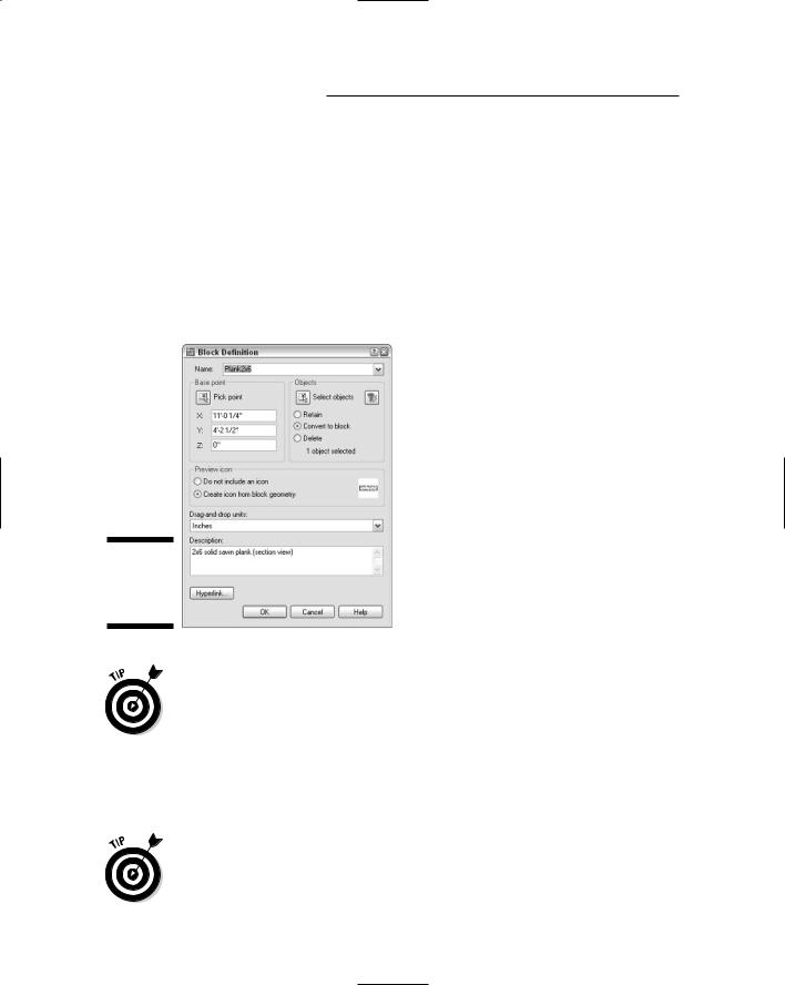
To create a block definition from objects in the current drawing, use the Block Definition dialog box. (The other way to create a block definition is by inserting another drawing file into your current drawing as a block, which I explain in the next section.) The following steps show you how to create a block definition using the Block Definition dialog box:
1.Click the Make Block button on the Draw toolbar.
The Block Definition dialog box appears (see Figure 13-1).
Figure 13-1:
The Block Definition dialog box.
Layers matter when you create the objects that makes up a block. Block geometry created on most layers retains the characteristics, such as color and linetype, of those layers. But if you create a block using geometry on Layer 0, that geometry has no characteristics, such as color and linetype of its own; chameleonlike, it takes on the features of the layer into which it’s inserted.
2. Type the block definition’s name in the Name text entry box.
If you type the name of an existing block definition, AutoCAD replaces that block definition with the new group of objects you select. This process is called block redefinition.
To see a list of the names of all the current blocks in your drawing, pull down the Name list.
Chapter 13: Playing Blocks and Rasteroids 299
3.Specify the base point, also known as the insertion point, of the block, using either of the following methods:
•Enter the coordinates of the insertion point in the X, Y, and Z text boxes.
•Click the Pick Point button and then select a point on the screen. (In this case, use an object snap or other precision technique, as described in Chapter 4, to grab a specific point on one of the block’s objects.)
The base point is the point on the block by which you insert it later, as I describe in the next section.
Use an obvious and consistent point on the group of objects for the base point, such as the lower-left corner, so that you know what to expect when you insert the block.
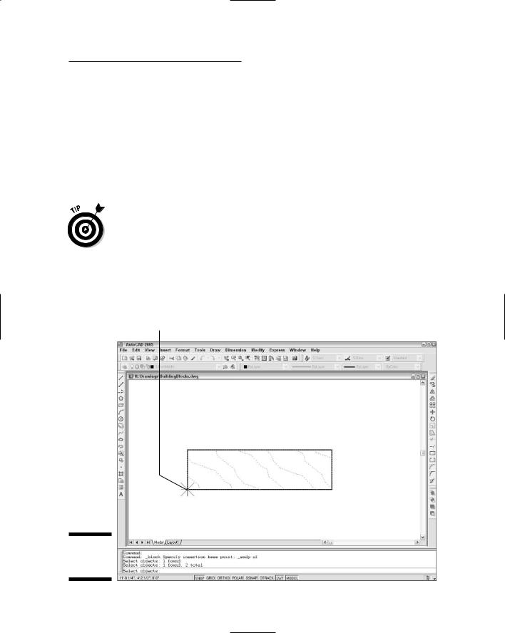
4.Click the Select Objects button and then select the objects that you want as part of the block.
AutoCAD uses the selected objects to create a block definition. Figure 13-2 shows the base point and group of selected objects during the process of creating a new block definition.
Base point
Figure 13-2:
Building a
block.