

AutoCAD 2005 For Dummies (2004)
.pdf240 Part III: If Drawings Could Talk
Following Lines and Arrows
The settings on the Lines and Arrows tab control the basic look and feel of all parts of your dimensions except text. Use this tab to change the type and size of arrowheads or the display characteristics of the dimension and extension lines.
Tabbing to Text
Use the Text tab to control how your dimension text looks — the text style and height to use (see Chapter 9) and where to place the text with respect to the dimension and extension lines. You’ll probably want to change the Text Style setting to something that uses a more pleasing font than the dorky default Txt.shx font, such as the Romans.shx font. The default Text Height is too large for most situations — set it to 1⁄8”, 3mm, or another height that makes sense. Figure 10-7 shows one company’s standard text settings.
Figure 10-7:
Whip your dimension text into shape.
The text style that you specify for a dimension style must be a variable height style — that is, the height that you specify in the Text Style dialog box must be zero. (See Chapter 9 for more information about variable height and fixed height text styles.) If you specify a fixed height text style for a dimension style, the text style’s height will override the Text Height setting in the New/Modify Dimension Style subdialog box. This behavior is confusing at best and unacceptable at worst. Use a variable height style to avoid the problem.
Enter the desired plotted text height. Don’t multiply it by the drawing scale factor, as you do for ordinary text.
Chapter 10: Entering New Dimensions 241
Industry or company standards usually dictate the size of dimension text. (For example, 1⁄8 inch is common in the architectural industry.) In any case, make sure you pick a height that’s not too small to read on your smallest check plot.
AutoCAD 2005’s new background mask feature, described in Chapter 9, works for dimension text, too. To turn on masking, choose either Background or a specific color from the Fill Color drop-down list. When you do, AutoCAD hides the portions of any objects that lie underneath dimension text. (To ensure that dimension text lies on top of other objects, use the DRaworder or TEXTTOFRONT command — see Chapter 9 for more information.
Getting Fit
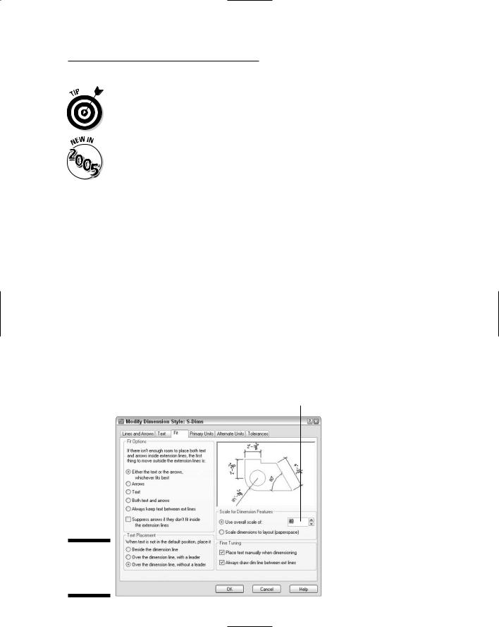
The Fit tab includes a bunch of confusing options that control when and where AutoCAD shoves the dimension text if it doesn’t quite fit between the dimension lines. The default settings leave AutoCAD in “maximum attempt at being helpful mode” — that is, AutoCAD moves the text, dimension lines, and arrows around automatically so that things don’t overlap. If these guesses seem less than satisfactory to you, try the modified settings shown in Figure 10-7: Select the Over the Dimension Line, without a Leader radio box under Text Placement and the Always Draw Dim Line between Ext Lines check box under Fine Tuning. (You can always move the text yourself by grip editing it, as I describe later in this chapter.)
Most important, the Fit tab includes the Use Overall Scale Of setting, as noted in Figure 10-8. This setting acts as a global scaling factor for all the other length-related dimension settings. Always set Use Overall Scale Of to the drawing scale factor of the current drawing.
Drawing scale factor goes here
Figure 10-8:
Keep Fit and
don’t forget
the Scale.
242 Part III: If Drawings Could Talk
If your drawing includes areas of different scales, you can create multiple dimension styles, one for each scale. Alternatively, you can set the Use Overall Scale Of setting to 1.0 and draw dimensions in a paper space layout, rather than in model space. See the “Trans-spatial dimensioning” section, later in this chapter, for more information.
The Use Overall Scale Of setting corresponds to the DIMSCALE system variable, and you’ll hear AutoCAD drafters refer to it as such. AutoCAD accepts zero as a special DIMSCALE setting for dimensioning in paper space layouts. Look up the DIMSCALE system variable in the AutoCAD online help system for more information about additional dimension scale options.
Using Primary Units
The Primary Units tab gives you incredibly — or maybe overly — detailed control over how AutoCAD formats the characters in the dimension text string. You usually want to set the Unit format and Precision and maybe specify a suffix for unit-less numbers, such as mm for millimeters. You may also change the Zero Suppression settings, depending on whether you want dimension text to read 0.5000, .5000, or 0.5. (“Zero Suppression!” also makes a great rallying cry for organizing your fellow AutoCAD drafters.)
Other style settings
If your work requires that you show dimensions in two different units (such as inches and millimeters), use the Alternate Units tab to turn on and control alternate units. If your work requires listing construction tolerances (for example, 3.5 mm +/–0.01), use the Tolerances tab to configure the tolerance format that you want.
The New/Modify Dimension Style dialog box Tolerance tab settings are for adding manufacturing tolerances (for example, +0.2 or -0.1) to the text of ordinary dimensions — the kind of dimensions I cover in this chapter. AutoCAD also includes a separate TOLERANCES command that draws special symbols called geometric tolerances. If you need these symbols, you probably know it; if you’ve never heard of them, just ignore them. Look up “Geometric Tolerance dialog box” on the Index tab in the AutoCAD online help system for more information.
Drawing Dimensions
After you’ve copied or created a suitable dimension style, you’re ready to dimension. Fortunately, adding dimensions to a drawing with existing dimension styles is usually pretty straightforward.
When you want to dimension something in AutoCAD, you can either select the object, such as a line or polyline segment, or select points on that object, such as the endpoints of the line or polyline segment. If you select an object,
Chapter 10: Entering New Dimensions 243
AutoCAD finds the most obvious points on it to dimension, such as the endpoints of a line. If you choose to select individual points instead, use object snaps (see Chapter 4). The points that you pick — or that AutoCAD finds for you — are called the origins of the dimension’s extension lines. When you change the size of the object (for example, by stretching it), AutoCAD automatically moves the dimension’s origin points and updates the dimension text to show the new length.
If you don’t use object snaps or another AutoCAD precision technique to choose dimension points, the dimension text probably won’t reflect the precise measurement of the object. This lack of precision can cause serious problems. When in doubt, osnap to it!
When you set up a new drawing, make sure that you change the Use Overall Scale Of setting on the Fit tab in the New/Modify Dimension Style dialog box so that it matches the drawing scale factor. Before you draw any dimensions in a drawing that you didn’t set up, check this setting to make sure it’s correct.
The AutoCAD dimension drawing commands prompt you with useful information at the command line. Read the command line prompts during every step of the command, especially when you’re trying a dimensioning command for the first time.
Lining up some linear dimensions
Linear dimensions are the most common type of dimensions, and horizontal and vertical are the most common of those. The following example demonstrates all the important techniques for creating horizontal and vertical linear dimensions, as well as aligned dimensions (which are similar to linear dimensions):
1.Use the LINE command to draw a nonorthogonal line — that is, a line segment that’s not horizontal or vertical.
An angle of about 30 degrees works well for this example.
If you want to apply dimensioning to an object other than a line, use these steps as a general guideline, filling in the appropriate commands and data as applicable to your drawing.
2.Set a layer that’s appropriate for dimensions current.
See Chapter 4 for details.
3.Set a dimension style that’s appropriate for your needs current.
Choose an existing dimension style from the Dim Style Control drop-down list on the Styles toolbar, or create a new style by using the procedure in the section, “Creating and managing dimension styles,” earlier in this chapter.
244 Part III: If Drawings Could Talk
4.Choose Dimension Linear or click the Linear Dimension button on the Dimension toolbar.
AutoCAD prompts you:
Specify first extension line origin or <select object>:
5.To specify the origin of the first extension line, snap to the lower-left endpoint of the line by using endpoint object snap.
If you don’t have endpoint as one of your current running object snaps, specify a single endpoint object snap by holding down the Shift key, rightclicking, and choosing Endpoint from the cursor menu. (See Chapter 4 for more about object snaps.)
AutoCAD prompts you:
Specify second extension line origin:
6.To specify the origin of the second extension line, snap to the other endpoint of the line by using endpoint object snap again.
AutoCAD draws a horizontal dimension — the length of the displacement in the left-to-right direction — if you move the cursor above or below the line. It draws a vertical dimension — the length of the displacement in the up-and-down direction — if you move the cursor to the left or right of the line.
AutoCAD prompts you:
Specify dimension line location or
[Mtext/Text/Angle/Horizontal/Vertical/Rotated]:
7.Move the mouse to generate the type of dimension you want, horizontal or vertical, and then click wherever you want to place the dimension line.
When you’re specifying the dimension line location, you usually don’t want to object snap to existing objects — you want the dimension line and text to sit in a relatively empty part of the drawing rather than bump into existing objects. If necessary, temporarily turn off running object snap (for example, click the OSNAP button on the status bar) in order to avoid snapping the dimension line to an existing object.
AutoCAD draws the dimension.
If you want to be able to align subsequent dimension lines easily, turn on Snap and set a suitable snap spacing — more easily done than said! — before you pick the point that determines the location of the dimension line. See Chapter 4 for more information about snap.
8.Repeat Steps 4 through 7 to create another linear dimension of the opposite orientation (vertical or horizontal).
Chapter 10: Entering New Dimensions 245
9.Choose Dimension Aligned or click the Aligned Dimension button on the Dimension toolbar.
The prompt includes an option to select an object instead of picking two points (you can use this technique with the Linear Dimension command, too):
Specify first extension line origin or <select object>:
10.Press Enter to choose the select object option.
AutoCAD prompts you:
Select object to dimension:
11.Select the line or other object that you want to dimension.
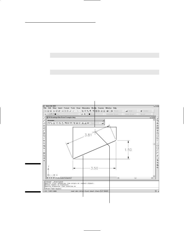
AutoCAD automatically finds the endpoints of the line and uses them as the extension line origin points, as shown in Figure 10-9.
AutoCAD uses endpoints as dimension origin points
Figure 10-9:
Drawing a linear dimension by selecting an object.
Select a line
Specify dimension line placement
246 Part III: If Drawings Could Talk
AutoCAD prompts you:
Specify dimension line location or
[Mtext/Text/Angle]:
12.Click wherever you want to place the dimension line.
AutoCAD draws the dimension.
Drawing other kinds of dimensions
After you have the hang of ordinary linear dimensions, you should be able to master other common dimension types quickly. Draw some lines, arcs, and circles, and try the other dimension commands on the Dimension toolbar or menu.
Although AutoCAD includes special commands for dimensioning the diameter or radius of a circle or arc, you can use the linear dimension techniques described in the previous section to dimension these objects.
To draw a series of side-by-side dimensions whose dimension lines are perfectly aligned, use the DimCOntinue command. To draw an overall dimension above one or more smaller dimensions, use DimBAseline. If you use these commands often in your work, you may find that the QDIM (Quick DIMension) command provides a quick way to draw lots of dimensions in one fell swoop.
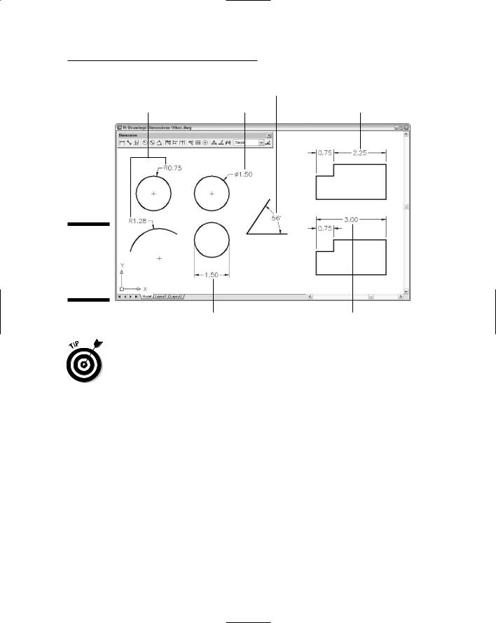
Figure 10-10 shows some results of using the more common additional dimensioning commands.
Trans-spatial dimensioning
Trans-spatial dimensioning may sound like the latest New Age fad — after all, most of Autodesk’s programmers do work in California — but actually it’s just a relatively new (circa AutoCAD 2002) dimensioning feature. There’s an ageold argument about whether to draw dimensions in model space, where the geometry that you’re dimensioning usually resides, or paper space. (See Chapter 3 for information about model space and paper space.) Most people have settled on dimensioning in model space, but sometimes dimensioning in paper space offers advantages — for example, when you want to dimension different parts of the same geometry in different paper space viewports.
Since AutoCAD 2002, the program works much better for dimensioning in paper space layouts — when you set the DIMSCALE system variable to 1.0 and then draw dimensions in paper space, AutoCAD can associate them with objects in model space.
Chapter 10: Entering New Dimensions 247
|
DimANgular |
|
DimRAdius |
DimDIameter |
DimCOntinue |
Figure 10-10:
Examples of additional dimensioning commands.
DimLInear |
DimBAseline |
Get comfortable with dimensioning in model space first. If you later want to try dimensioning in paper space, look up “dimensioning, methods” in the AutoCAD online help system.
Editing Dimensions
After you draw dimensions, you can edit the position of the various parts of each dimension and change the contents of the dimension text. AutoCAD groups all the parts of a dimension into a single object.
Editing dimension geometry
The easiest way to change the location of dimension parts is to use grip editing, which I describe in Chapter 6. Just click a dimension, click one of its grips, and maneuver away. You’ll discover that certain grips control certain directions of movement. Experiment a few minutes to see how they work.
If you want to change the look of a dimension part (for example, substitute a different arrowhead or suppress an extension line), use the Properties

248 Part III: If Drawings Could Talk
palette. (See Chapter 6 for more on the Properties palette.) All the dimension settings in the New/Modify Dimension Style dialog box (see “Adjusting style settings,” earlier in this chapter) are available in the Properties palette when you select one or more dimensions.
If you select one or more dimensions and right-click, the cursor menu displays a number of useful options for overriding dimension settings or assigning a different style.
When you change a setting in the Properties palette, you’re overriding the default style setting for that dimension. If you need to make the same change to a bunch of dimensions, it’s better to create a new dimension style and assign that style to them. You can use the Properties palette or the right-click menu to change the dimension style that’s assigned to one or more dimensions.
You can use the Properties palette to turn on AutoCAD 2005’s new background mask feature, described in Chapter 9, for the text of individual dimensions: Select the dimensions, display the Text area in the Properties palette, and choose either Background or a specific color from the Fill Color dropdown list. Note that turning on background mask in the Multiline Text Editor window, as Chapter 9 tells you to do for regular (nondimension) text, does not work for dimension text. You must use the Fill Color setting on either the Text tab of the New/Modify Dimension Style dialog box (as described earlier in this chapter) or the Properties palette.
The AutoCAD eXplode command on the Modify toolbar will blow a dimension apart, into a bunch of line and multiline text objects. Don’t do it! Exploding a dimension makes it much harder to edit cleanly and eliminates AutoCAD’s capability of updating the dimension text measurement automatically.
Editing dimension text
In most cases, you shouldn’t have to edit dimension text. Assuming that you drew your geometry accurately and picked the dimension points pre-
cisely, AutoCAD displays the right measurement. If you change the size of the associated object, AutoCAD updates the dimension and its measurement. However, you occasionally may need to override the dimension text (that is, replace it with a different measurement) or add a prefix or a suffix to the true measurement.
AutoCAD creates dimension text as a multiline text (mText) object, so dimension text has the same editing options as ordinary text. Unfortunately, the right-click menu for dimension objects doesn’t include a Text Edit option. You can use the Text Override field in the Properties palette, or type ED (the keyboard shortcut for the ddEDit command) to edit dimension text in the Multiline Text Editor window.
Chapter 10: Entering New Dimensions 249
The default text is <> (that is, the left and right angled bracket characters), which acts as a placeholder for the true length. In other words, AutoCAD displays the true dimension length as text in the actual dimension (and keeps the text up-to-date if you change the distance between the dimension’s origin points). You can override the true length by typing a specific length or other text string. You can preserve the true length but add a prefix or suffix by typing it before or after the leftand right-angled bracket characters. In other words, if you enter <> Max., and the actual distance is 12.00, AutoCAD displays 12.00 Max. for the dimension text. If you later stretch the object so that the actual distance changes to 14.50, AutoCAD automatically changes the dimension text to read 14.50 Max. Now you can appreciate the importance of drawing and editing geometry precisely!
Avoid the temptation to override the default dimension text by replacing the angled brackets with a numeric value. Doing so eliminates AutoCAD’s capability of keeping dimension measurements current, but even worse, you get no visual cue that the default distance has been overridden (unless you edit the dimension text). If you’re overriding dimension text a lot, it’s probably a sign that the creator of the drawing didn’t pay enough attention to using precision techniques when drawing and editing. I’m not going to point any fingers, but you probably know whom to talk to.
Controlling and editing dimension associativity
When you add dimensions by selecting objects or picking points on the objects by using object snap modes, AutoCAD normally creates geometrydriven associative dimensions, which are connected to the objects and move with them. This is the case in new drawings that were originally created in any version of AutoCAD starting with 2002. (Autodesk introduced geometrydriven dimensions in AutoCAD 2002. Before that, AutoCAD normally created dimensions whose parts functioned as a single grouped object but that weren’t connected with the dimensioned object.)
In drawings that were created originally in versions older than AutoCAD 2002, you must set the new DIMASSOC system variable to 2 before AutoCAD 2005 will create geometry-driven associative dimensions. An easy way to make this change for the current drawing is to open the Options dialog box (choose Tools Options), click the User Preferences tab, and turn on the Make New Dimensions Associative setting. Be aware that this setting affects only new dimensions that you draw from now on. Thus, you’ll end up with geometrydriven associative new dimensions and less than fully associative existing dimensions in your old drawing. Look up “DIMASSOC system variable” in the AutoCAD online help system for more information.