Добавил:
Опубликованный материал нарушает ваши авторские права? Сообщите нам.
Вуз: Предмет: Файл:

3D Game Programming All In One (2004)

.pdf
Скачиваний:
140
Добавлен:
17.08.2013
Размер:
17.91 Mб
Скачать

428Chapter 14 Making a Character Model

35.Unhide all the hidden vertices using the Edit, Unhide All command.

36.Select all the vertices from both meshes located at the places where you placed the dragged vertices. It's probably best to do this with the Right Side view, as I did in Figure 14.35. These are the vertices of each mesh, chest and ab, that share the same locations.

37.Choose Vertex, Snap To Grid. This should have

Figure 14.34 The top center cylinder vertex.

Figure 14.35 Selecting the common chest and ab vertices.

Figure 14.36 After snapping to grid…oops!

the effect of forcing the closely adjacent vertices of each mesh to exactly align on the grid locations. However, if your vertices weren't aligned closely enough earlier, then they might diverge, as you can see happened to me in Figure 14.36. That's because I didn't take my own advice to zoom in and tweak each moved vertex position to be exactly right.

It should be pretty obvious where the misaligned vertices have to go. If you have any that wandered off like I did, go back to the Right Side view and the Front view and move the wayward vertices into position. Then repeat the Snap To Grid operation.

38.Compare your results with the images in Figure 14.37, making sure you have the same thing as shown there.

39.If they aren't already selected, reselect the vertices shown back there in Figure 14.35.

40.And now the moment we've all been waiting for: Choose Vertex, Weld Vertices.

All vertices that share identical common coordinates will be "welded" together. This basically means that superfluous copies of vertices will be deleted, and the polygons that we're defining will be reattached to the remaining single copy of each vertex.

41.In the Groups tab in the toolbox, choose both meshes, the chest and ab, so that they are both selected and highlighted in the wire-frame views.

42. Click Regroup, and then rename the newly consolidated group as "torso".

Team LRN

The Base Hero Model

429

You can now consider the torso to be finished. However, you can probably see areas where you can make obvious tweaks and

adjustments. I

did a few, just Figure 14.37 The well-aligned vertices.

to make the

integration of the back and the behind as well as the chest and the front abdomen a bit more natural looking. I also added a wee bit of "anatomical correctness," so to speak. Figure 14.38 shows the results of my tweaks. It should be fairly painless for you to duplicate these adjustments. The only operations I performed were Select (Vertex) and Move.

43.Save your mytorso.ms3d file so you don't lose all your work.

Figure 14.38 The final torso.

Matching the Head to the Torso

Now we should make sure that the torso and the head match correctly.

1.Choose File, Merge and browse until you find your head file, which should be at C:\3DGPAi1\resources\ch14\myhead.ms3d. Your head mesh will be loaded in, centered around the origin.

2.On the Groups tab in the toolbox, choose the new object (your torso mesh will be called "torso", so the merged head mesh will be the other one). Rename it as "head".

3.Click the Select button so that the head mesh is highlighted (and the torso mesh isn't), drag the head up in either the Front or the Side view, and position it as shown in Figure 14.39.

I see two things I don't like right away—the head is bigger than it should be, and it also seems that its shape is a little too…ummm…blah. This isn't hard to fix, however.

4.Scale the head to 75 percent in the Y-axis only.

Team LRN

430 Chapter 14 Making a Character Model

Figure 14.39 Matching head to torso.

Figure 14.40 The reshaped head.

5.Move the head down until it just touches the top of the torso.

6.Rotate the head by 5 degrees around the X-axis so that the face is pointing a little bit down, as shown in Figure 14.40.

There, that's more like it! Now to fiddle with the torso some more.

7.Select the vertices that form the shoulder sockets on both sides of the torso, using Figure 14.41 as a guide.

8.Scale the vertices to 60 percent in the Y- and Z-axes.

9.Save your work as C:\3DGPAi1\ resources\ch14\mytorso.ms3d.

As we create the remaining parts of the model, we'll add them to this model by merging as we go along.

The Legs

When we start the legs, we'll want to keep the torso mesh around to use as a sizing reference, at least for the first little while. However, we won't need to have the head mesh in there, cluttering things up, so we'll get rid of that.

1.If you haven't already, save your torso as C:\3DGPAi1\resources\ch14\mytorso.ms3d.

2.Now save your file as C:\3DGPAi1\ resources\ch14\my legs.ms3d.

3.Delete the head mesh using the Groups tab in the toolbox.

Figure 14.41 The shoulder socket vertices.

Team LRN

The Base Hero Model

431

4.Select the torso mesh and drag it up about one torso's length above the origin.

5.Create a cylinder with 3 segments (stacks) and 12 slices (faces), and position and shape it as shown in Figure 14.42. This is the foot.

6.Create another cylinder and rotate it 90 degrees in the Z-axis, making sure that it is oriented so it runs left to right where the knee would be.

7.Using Figure 14.43 as a guide, move the vertices of the top of the foot up to meet the knee cylinder.

By now you've probably realized that almost everything from here on is more a matter of style and taste, and less of technique. So you

should feel free to go ahead and deviate from the specific construction details if you think of something you might like better.

8.Reshape the knee cylinder as shown in Figure 14.44.

9.Select the foot cylinder and rename it as "LeftFoot".

10.Create two more cylinders, and orient them as shown in Figure 14.44 to make the upper leg and hip.

Figure 14.42 Shape and placement of the foot.

Figure 14.43 The knee.

Figure 14.44 The left thigh.

Team LRN

432Chapter 14 Making a Character Model

11.Select the two new cylinders, plus the knee cylinder, and use the Regroup tool in the Groups tab of the toolbox. Name the resulting mesh "LeftThigh".

12.Shape the left thigh to match that shown in Figure 14.45—or to suit your own evil purposes.

13.With the left foot mesh selected, choose Edit, Duplicate. A duplicate of the leg is created in exactly the same location of the original, so you can't see it yet.

14.Choose Vertex, Mirror Left<--> Right. The duplicate leg mesh now appears on the other side, and in the right place, or pretty darn close.

15.Rename the new leg mesh as "RightFoot".

16.Now duplicate and mirror the left thigh in the same way, renaming the new thigh mesh as "RightThigh". You should now have two legs, each made up of a thigh mesh and a foot mesh and named appropriately.

17.Next, delete the torso mesh from the model. (You did save the torso in its own file earlier when I suggested it, right?)

18.Save your work! You should be saving this as C:\3DGPAi1\resources\ ch14\mylegs.ms3d.

Figure 14.45 The finished left leg.

Integrating the Legs to the Torso

Figure 14.46 The Hero model with head, torso, and legs.

Just as we did with the head, we now have to integrate the legs with the rest of our model.

1.Open the file C:\3DGPAi1\resources\ ch14\myhero.ms3d.

2.Select File, Merge, and choose the legs file you just created, which should be called C:\3DGPAi1\resources\ch14\mylegs.ms3d.

3.Choose the right leg, right thigh, left foot, and left thigh meshes and move them into position. You should now have a model pretty close to the one shown in Figure 14.46.

Team LRN

The Base Hero Model

433

The Arms

Finally, the last set of meshes in the model. We can create the arms in exactly the same way we created the legs—building up from shape primitives, splicing them together until we have the desired mesh topology.

With arms comes the perennial question—what to do about the fingers? In some models we can make detailed meshes for each finger, with cylinders segmented at the knuckles, and so on. However, we must keep in mind that our goal here is to create a low-poly model, and that typically means fewer than about 1,500 polygons in the model. If we go over that count by a small amount, no big whoop, but we must remain mindful of it.

So, let's get to work!

1.Open your saved mytorso.ms3d file, and resave it as myarms.ms3d in the same location as your other work files.

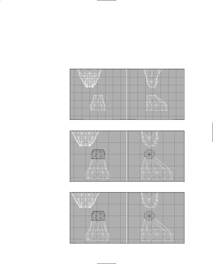
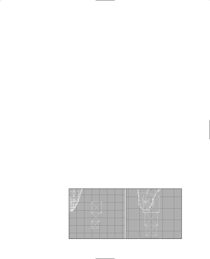
2.Create a box offset to the left side (on the right in the Front view) of the torso, situated low near the bottom of the torso.

3.Duplicate this box and move the copy to abut the bottom of the original box.

4.Scale the second box to 80 percent.

5.Duplicate the second box and move the new box below the second.

6.Scale the third box to 80 percent of the second box.

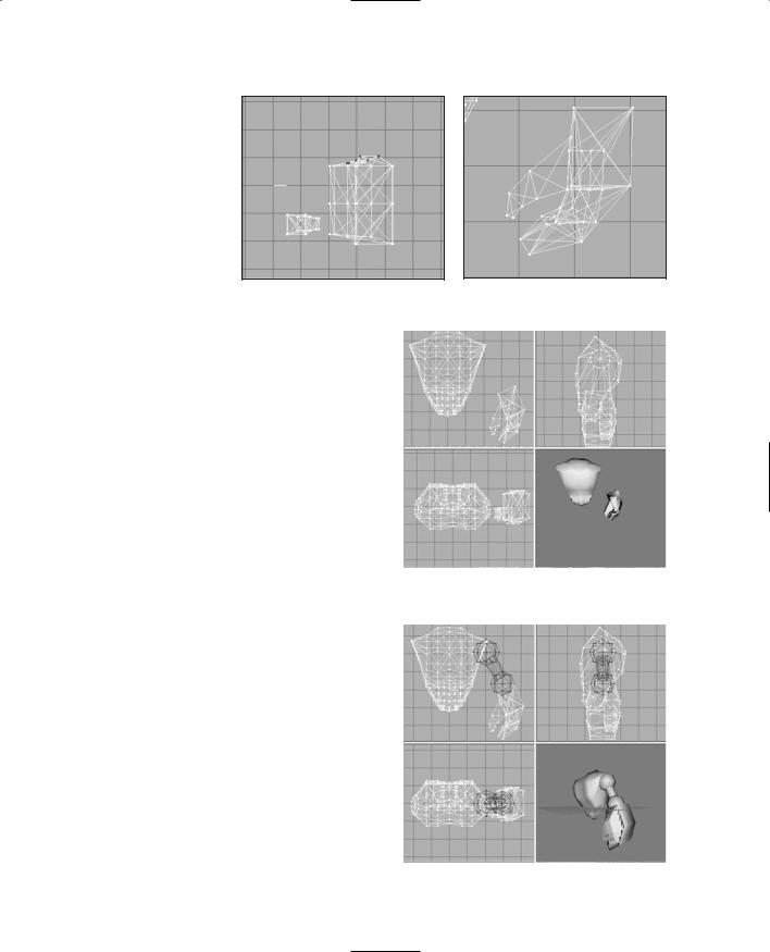
7.Align the boxes as shown in Figure 14.47.

8.Hide the torso mesh to keep it out of the way for the moment.

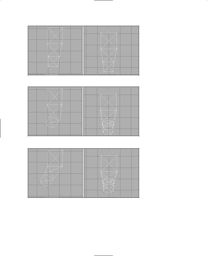
9.Using Vertex Selection, the Move tool, and the Snap To Grid and Weld tools as you did with earlier parts of the Hero model, align the vertices of the three boxes as shown in Figure 14.48, and weld the vertices together.

10.Rotate the two bottom rows of vertices by 30 degrees in the Z-axis, as shown in Figure 14.49.

11.Move the two bottom rows in the Front view to align them as shown in Figure 14.50.

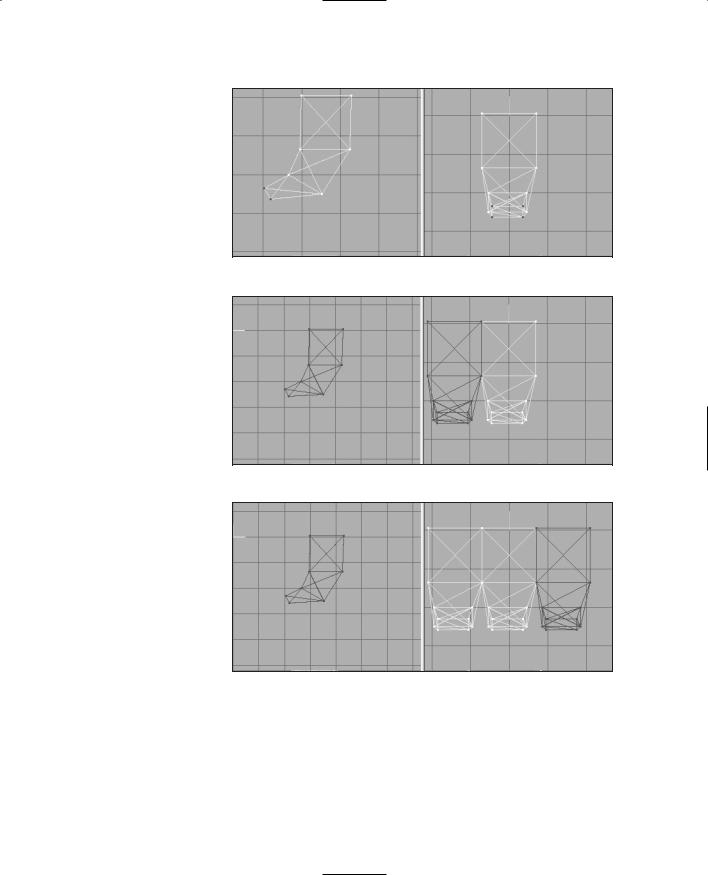
12.Rotate and move the bottom row of vertices to match what is shown in Figure 14.51.

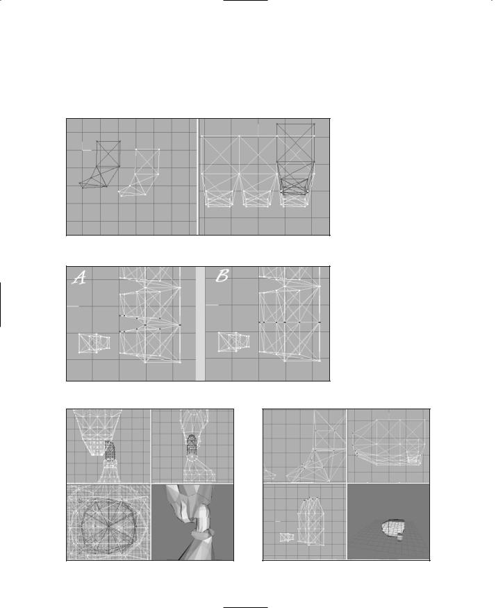
13.Now, setting the Select mode

to Groups, select all the

groups of Figure 14.47 Alignment of the three boxes.

Team LRN

434 Chapter 14 Making a Character Model

Figure 14.48 Welding the hand vertices.

Figure 14.49 Rotating the two bottom rows.

Figure 14.50 Moving the two bottom rows.

boxes, duplicate them, and move them forward to abut the front of the original boxes, using Figure 14.52 as a guide.

14.Now repeat the process in step 13, putting the new copies at the rear of the originals, using Figure 14.53 as a guide.

15.Now repeat the duplicating process one more time, but this time move the new boxes to the left side of the Front view. This is the thumb.

16.Choose Vertex, Mirror Left <--> Right to reverse the orientation of the thumb boxes (see Figure 14.54), and then scale the thumb to 50 percent.

Team LRN

17.Now we'll switch back to the hand part. In the Top view, select the vertices that are adjacent in the two forward parts of the hand boxes, as shown in Figure 14.55, panel A. Then choose Vertex, Flatten, Z and the vertices will be brought together onto a common plane, as shown in Panel B of Figure 14.55.

18.Double-check the other views, and if all vertices look to be coincident, then choose Vertex, Weld Together to weld them.

The Base Hero Model

435

Figure 14.51 The bottom row of vertices.

Figure 14.52 Two sets of shaped boxes abutting each other.

19. Repeat step 18

for the rear part

Figure 14.53 Three sets of shaped boxes.

of the hand,


welding the result. Compare with Figure 14.56 to make sure it is correct.

20.Select the rearmost vertices, in the baby finger area, and scale them to 50 percent in the X- and Y-axes, as shown in Figure 14.57.

21.Move the scaled vertices forward until they are close to the middle hand boxes, using the Top view in Figure 14.58 as a guide.

22.Repeat steps 20 and 21 for the front index finger area.

Team LRN

436Chapter 14 Making a Character Model

23.In the Front view, rotate and shape the thumb to approximate what's shown in Figure 14.59.

24.Unhide the torso and compare the size and positioning of your hand with the views shown in Figure 14.60. Rotate the hand to match, if required.

Figure 14.54 The start of the thumb.

Figure 14.55 Welding the hand vertices.

Now you might be thinking that the hand looks awfully blocky compared to other parts of the model. You are right, but take heart. We can compensate for this with our skins. Remember, we want to keep our polygon count as low as we can.

25.Using the Groups tab in the toolbox, select all the hand groups, regroup them to form a new mesh, and rename it as "LeftHand".

Figure 14.56 After the hand welding.

Figure 14.57 The scaled baby finger area.

Team LRN

The Base Hero Model

437

26.In the Front view, use the Sphere tool set to four stacks and

eight slices, and create a sphere that completely fills the left


shoulder

Figure 14.58 Placing the scaled

Figure 14.59 The thumb


baby finger vertices.


positioning.


socket of the


torso. Check all your views to make


sure that you have it pretty close.


27.

Make another sphere with the same


settings that fills the top of the hand,


and place it there.


28.

Make a one-stack, eight-slice cylinder


that you can rotate and move into a


position that connects the two spheres.


Use Figure 14.61 as a guide for sphere


and cylinder sizing and placement.


29.

Select all the upper arm components,


regroup them, and name the new mesh


Figure 14.60

Comparison of torso with


"LeftArm".


30.

Select the new left arm mesh, duplicate

hand.


it, and then choose Vertex, Mirror


Right <--> Left.


31.

Adjust the new mesh if necessary, and


rename it as "RightArm".


32.

Repeat the duplicating and renaming


operations for the left hand mesh.


33.

Delete the torso mesh.


34.

Save your work! You should now have a


pair of hefty arms that closely resemble


those shown in Figure 14.62.


Figure 14.61

The left arm.

Team LRN