

3D Game Programming All In One (2004)
.pdf418 Chapter 14 ■ Making a Character Model
■head
■torso
■right leg
■left leg
■right arm
■left arm
So that's six segments in all. (A continuous-mesh model would have one segment.) All the leg and arm segments will each have two subsegments. Each segment or subsegment can be thought of as an individual mesh, or submesh.
The Head
We'll use the Shape Primitives approach to build the head. The keys to successful use of this technique are (1) choose the right primitive and (2) use a primitive with sufficient vertices to do the job.
For the head part of the model, we're going to use a cylinder with 12 faces on the tube, stacked 6 segments high. That translates to a 6-stack, 12-slice cylinder, in MilkShape terms.
1.Open MilkShape, create a new document, and set the Point Size to 3 and the Grid to 1 1 in the Preferences dialog box. Save the new file as C:\3DGPAi1\resources\ch14\myhead.ms3d.
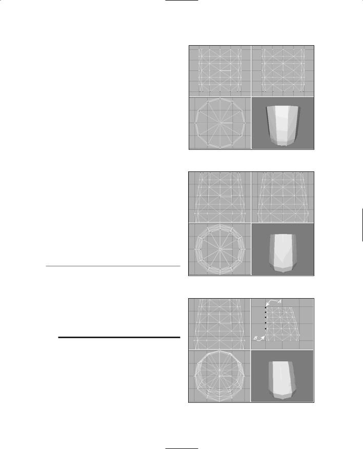
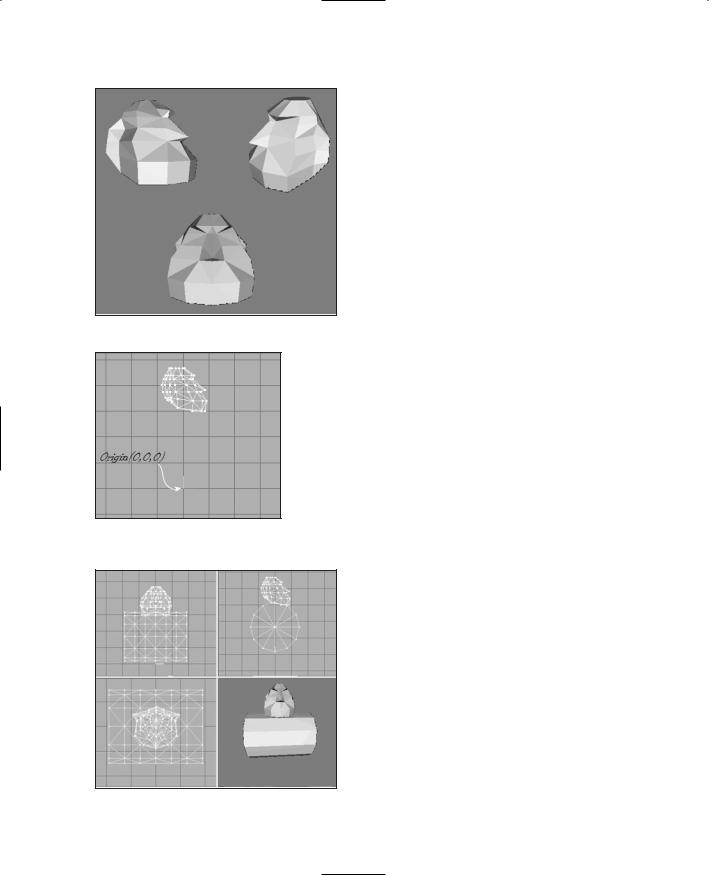
2.Create a 6-stack, 12-slice cylinder as depicted in Figure 14.1. Size the cylinder such that the bounds of the cylinder extend from about 20 to +20 on all three of the axes.
3.Choose Select in Vertex mode and then select the bottom layer of vertices.
4.Scale the selected bottom vertices to 95 percent of original, as depicted in Figure 14.2.
5.Now select the top five rows of vertices, ignoring the bottom two rows, and scale them to 95 percent.
6.Next, scale the top four rows of vertices to 95 percent.
7.Repeat the scaling operation for the top three, then the top two, and finally the top row by itself. You should now have a cylinder with a bit of a bevel at the bottom that tapers gently toward the top, as
shown in Figure 14.3.
Figure 14.1 The initial cylinder.
Team LRN
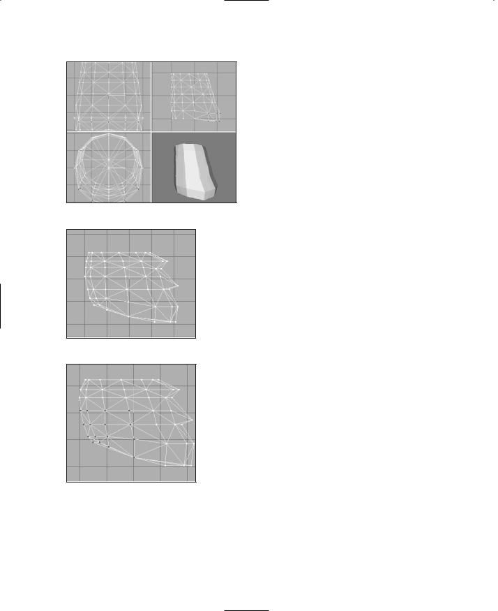
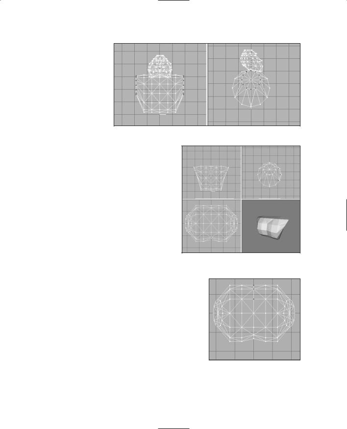
8.Next, shift the top five layers of the cylinder toward the back, so that the rearmost vertices (designated A, highlighted in black, in Figure 14.4) line up, at the back, with the layer of vertices that is second from the bottom (B in Figure 14.4). They don't have to be aligned precisely, but try to get them pretty close, as shown in Figure 14.4.
9.Next, working from the Side view (Top Right viewport), select the bottom six vertices visible in that view (at the right side of the view) and move them down and to the right a bit. Figure 14.5 shows which vertices you want and how far to move them. These vertices make up the jaw.
10.Select all the vertices in the model, and scale to 75 percent in the Y-axis only. Do this by typing the value 0.75 into the Y scale box when you have the Scale tool selected and then clicking Scale.
t i p
The view in what MilkShape calls the Left viewport is for us actually the Right view (or Right Side view) located in the upper-right frame, because Torque's coordinate system is oriented differently. It's because of this that I normally use MilkShape with the Show Viewport Caption option under the Window menu turned off, in order to avoid confusing myself.
11.Now, using the same technique of selecting and moving (without doing any scaling) as used in steps 4 to 9 above, shape the model as near as you can get to Figure 14.6. This is the Right Side view (upper right frame). You only need to work in this view,
The Base Hero Model |
419 |
Figure 14.2 Selecting the bottom vertices.
Figure 14.3 Tapering the cylinder.
Figure 14.4 Shifting the layers.
Team LRN
420 Chapter 14 ■ Making a Character Model
Figure 14.5 Shaping the jaw.
Figure 14.6 Shaping the head.
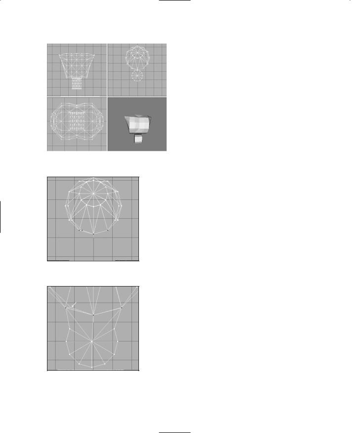
Figure 14.7 Back of the head/upper neck.
and no other, and only use the Select and Move tools. Now you can see the head shape taking form in profile, with the nose jutting out.
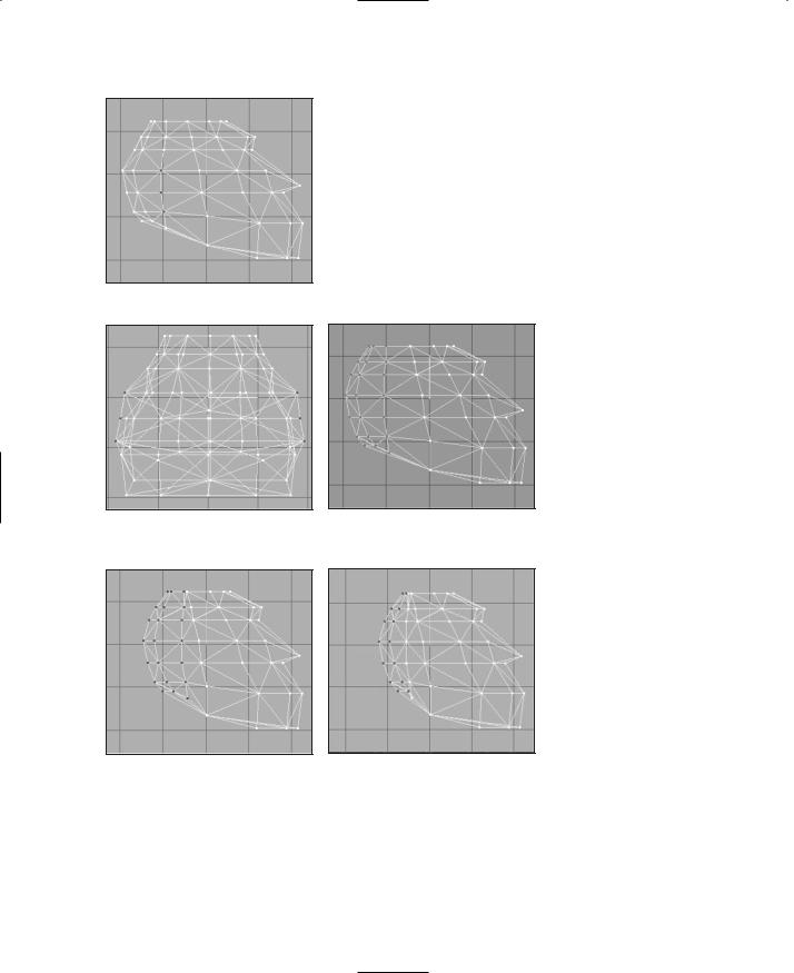
12.Okay, this next part gets a bit tricky. Using the Right Side view, select the 16 vertices in the lower-left corner (which is the lower back of the head/upper rear neck area), as shown in Figure 14.7.
13.Scale this group of vertices to 80 percent by typing 0.8 in the X-axis scale box, and then click Scale.
14.Now select just the nine vertices in the lower left, as shown in Figure 14.8, and scale these to 80 percent again.
What this does is make the jaw and cranium parts of the head stand out in an exaggerated fashion. By doing the scaling incrementally on the vertices in the region like that, we get a fairly smooth shape. Take a moment to swivel the model around in the 3D view, and you can now see a definite cartoonlike big-jawed, low-browed heroic figure taking shape. Okay, so not all heroes look like that. But we're making a game, right? So make it fun!
Now, as cute and lovable as that beetle-browed look is, it's a bit too Cro-Magnon and robotic looking, so we need to tone down the forehead and eyebrow area somewhat.
15.In the Right Side view, in the row of vertices that is second from the top (see Figure 14.9), select the vertex that is the second from the right (in the temple area) by dragging the Selection tool around it. This will have the effect of selecting that vertex and any others that are obscured behind it. There happens to be one more back there, so you will end up with two vertices selected, which you can see by examining the model in other views.
Team LRN

The Base Hero Model |
421 |
16. Drag the ver- |
|
|
tices back (to |
|
|
the left) a few |
|
|
ticks. |
|
|
17. Switching |
|
|
now to the |
|
|
Front view |
|
|
(upper left |
|
|
frame), scale |
|
|
those two ver- |
|
|
Figure 14.8 The smaller back of |
||
tices by 120 |
||
the head area. |
||
percent in the |
||
|
||
X-axis. This has the effect of widening the gap |
||
between them. (See Figure 14.10.) These steps |
||
have the effect of softening the sharp corners, just enough to make the head more organic looking.
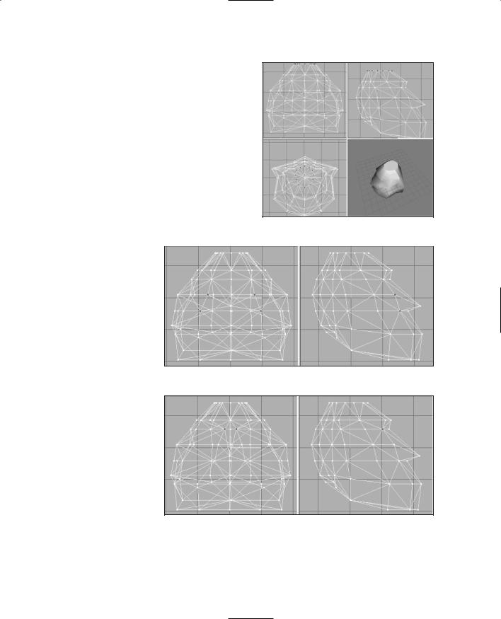
18.Still with the Front view, select all the vertices in the top three rows, which is mostly the cranium area, and then incrementally apply 90 percent X- axis and Z-axis scaling to them—as you did earlier: top three, then top two, and so on. Figure 14.11 shows the results we are looking for here.
19.If you haven't saved your work recently, do it now. No particular
reason, other than it's good practice. We're getting close to finished with the head.
Figure 14.9 The temple vertices.
Figure 14.10 Scaling the temple vertices.
20. Using Figure |
|
|
14.12 as a |
|
|
guide, select the |
|
|
three ear ver- |
|
|
Figure 14.11 Scaling the cranium. |
||
tices in the |
||
|
||
Right Side view. |
|
21.Stretch the ear vertices apart by scaling them 170 percent in the X-axis, as shown in Figure 14.13.
Team LRN
422Chapter 14 ■ Making a Character Model
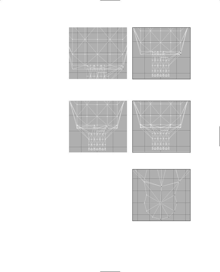
22.Now back in the Right Side view, guided by Figure 14.14, select the three columns of vertices at the rear of the head.
23.Drag them forward so that the rightmost column of selected vertices is just behind the unselected column (the fifth column), as shown in Figure 14.15.
24.Next drag the two columns at the back of the head forward, so that you end up with a configu-
Figure 14.12 The ear vertices.
Figure 14.13 The scaled ear vertices.
Figure 14.15 Dragging the vertices forward.
ration like the one depicted in Figure 14.16.
Figure 14.14 Selecting the three columns of vertices.
Figure 14.16 After dragging the vertices.
25.By now, you should be getting fairly adept at using the Select, Move, and Scale tools in MilkShape, so I'll give you a little assignment: Make the scalp region at the top of the head look like the scalp shown in Figure 14.17, using just these three tools and operating only on the top row of vertices. You will have to work in both the Front and Side views while monitoring your progress in the 3D view.
Team LRN
The Base Hero Model |
423 |
26.Next, use the same techniques to shape the nose and eyes. Figure 14.18 shows which vertices to use to shape the nose. Scale the vertices by 50 percent in the X-axis.
27.Shape the eye-socket vertices shown in Figure 14.19 by scaling to 30 percent in the X-axis.
28.Now, this entire work should exist as one group. Rename that group as "head" in the Groups tab in the toolbox.
29.Save your work as C:\3DGPAi1\
resources\ch14\myhead.ms3d. By |
Figure 14.17 Shaping the scalp. |
|
saving the head |
|
|
in its own file, |
|
|
you can keep it |
|
|
safely out of the |
|
|
way while you |
|
|
work on the |
|
|
other parts. |
|
|
And there you have it—as you can see in Figure 14.20, steely-eyed, bigjawed, beetle-browed genuine dyed-in-the- wool hero material!
The Torso
Like the head, the torso will be based on the cylinder shape, but this time we will use two of them and weld them together.
Figure 14.18 The nose vertices before scaling.
Figure 14.19 The eye-socket vertices after scaling.
1.If you have the
head file still open, leave it open. If you don't have it open, then open it.
Team LRN
424 Chapter 14 ■ Making a Character Model
2. Save the file as C:\3DGPAi1\resources\ ch14\mytorso.ms3d. We want to have the head around to use as a sizing guide when we start the torso model, and then we will delete it.
3. Drag the head mesh up until it is three or four grid lines above the model origin (the 0,0,0 coordinate), as suggested in Figure 14.21.
4. Use the Cylinder shape, and make one that has 6 segments, or stacks, and 12 slices, or faces. Give the name "chest" to
the group it creates.
Figure 14.20 The finished hero head.
5. Rotate the cylinder by 90 degrees in both the X- and Y-axes.
Figure 14.21 Positioning the head mesh.
6.Move and scale the cylinder until it has the same relationship to the head, as shown in Figure 14.22.
7.Turn the Auto Tool option off, if it is on.
8.In the Front view, select all the vertices from one end of the cylinder, then hold down the Shift key, and drag over the vertices at the other end of the cylinder to select them as well. These vertices form the cylinder caps for either end.
9.Scale the vertices to 50 percent in the Y- and Z- axes.
10.Drag the vertices up until the top ones are in line with the top of the cylinder. Figure 14.23 shows what the result should look like.
11.If you like to use the Auto Tool option, turn it back on now.
12.In the Front view, select the right-hand end cap, and rotate it by 20 degrees in the Z-axis.
13.Now rotate the left-hand end cap by +20 degrees in the Z-axis.
Figure 14.22 The relationship of the chest cylinder to the head.
Team LRN
The Base Hero Model |
425 |
14.In the Groups tab in the toolbox, choose the head group and delete it. This gets it out of the way so it won't clutter our model. We
have the head
saved sepa- Figure 14.23 The cylinder caps after scaling and moving.
rately, so no worries here.
15.In the Top view, select the two vertices in the middle at the bottom, in the area of the sternum, as shown in 14.24, and move them toward the inside of the chest a bit. Use Figure 14.24 as a guide.
16.Now you'll do the same for the back as for the front, but just slightly differently, for a different effect. In the Front view, select all the vertices in the top three rows, including the ones that are in the end caps.
17.Hide these vertices, using Edit, Hide Selection.
Figure 14.24 The sternum vertices after moving.
18.Now in the Top view, select the middle three vertices at the top of the view, as shown in Figure 14.25. These are the middle back vertices.
19.Move the middle back vertices toward the inside of the chest a bit, just as you did with the sternum, but perhaps not quite as much.
20.Create another new cylinder (to be named "ab"), and give it the same 90 degree rotation in the X- and Y-axes.
21.Move and scale the ab cylinder until it has the same relationship with the chest, as shown in Figure 14.26.
Figure 14.25 The middle back vertices.
Team LRN
426 Chapter 14 ■ Making a Character Model
|
Now we have our primitive abdomen |
|
inserted. We're going to have to splice |
|
that mesh onto the chest mesh in order |
|
to complete the torso. It's actually not |
|
terribly hard to do, and after you've |
|
done it once, it will seem intuitively |
|
easy. But there are quite a few fiddly lit- |
|
tle steps involved to get there from here. |
|
So please be patient. |
|
22. Using the Groups tab, hide the ab mesh. |
|
23. In the Right Side view, select the bot- |
|
tom vertices, as shown in Figure 14.27, |
Figure 14.26 The ab cylinder relative to the |
and then hide them using Edit, Hide |
chest. |
Selections. |
Figure 14.27 Hiding the lower chest vertices.
Figure 14.28 The ab vertices dragged over on top of the chest vertices.
24.Back to the Groups tab, unhide the ab mesh. Don't use the general Unhide All command, because we want the chest vertices that we just hid to stay hidden.
25.In the Right Side view again, select the vertices shown in 14.28 and drag them up so they are directly over the location where the hidden vertices for the chest are. Study Figure 14.28, which shows the vertices selected and dragged into position. Compare it with Figure 14.27 to get a sense of the right place to put the vertices. The intersection of lines shown by the white arrow in Figure 14.28 does not get a vertex at this time—we will deal with that shortly.
26.In the Front view, locate the end cap vertices, as shown in Figure 14.29, and drag them out to the position indicated in that figure.
27.Next, do the same for the vertices to the left of the previous set. Drag them to exactly the same place as the previous set, as shown in Figure 14.30.
28.Repeat steps 26 and 27 for the other end of the ab mesh.
29.Drag the next set of vertices over to the chest positions, as shown in Figure 14.31.
Team LRN
30. Repeat the |
|
|
|
drag opera- |
|
|
|
tion for the |
|
|
|
other end. |
|
|
|
You should |
|
|
|
now have |
|
|
|
something |
|
|
|
that closely |
|
|
|
resembles the |
|
|
|
layout in |
|
|
|
Figure 14.29 |
Dragging some |
||
Figure 14.32. |
|||
end cap vertices over on top of |
|||
|
|||
31. Zoom in on |
chest vertices. |
|
|
all the places |
|
|
|
that you |
|
|
|
dragged ver- |
|
|
|
tices to, and |
|
|
|
make sure |
|
|
|
that they are |
|
|
|
exactly over |
|
|
|
the line inter- |
|
|
|
sections of |
|
|
|
the chest tri- |
|
|
|
angles. |
|
|
|
Figure 14.31 |
Dragging the next |
||
32. In the Right |
|||
set of vertices into position. |
|||
Side view,
select and hide all vertices on a line from the center of the cylinder forward (with forward being toward the right of the view). Figure 14.33 shows the vertices we're interested in.
33.Back in the Front view, select the center vertex at the top of the ab cylinder, as depicted in Figure 14.34. If you've done step 32 correctly, then as you scan around the other views, you will see that only one vertex has been selected.
34.Switch to the Right Side view and drag that lone vertex up to the spot that I pointed out with the white arrow way back when in Figure 14.28.
The Base Hero Model |
427 |
Figure 14.30 Dragging the end cap neighbor vertices over on top of the chest vertices.
Figure 14.32 The final Front view layout.
Figure 14.33 Select and hide these vertices.
You should now have a configuration that looks like the one shown in Figure 14.35. Again, take the time to zoom in and ensure that all the dragged vertices are exactly over the line intersections of the chest triangles.
Team LRN