

3D Game Programming All In One (2004)
.pdf368Chapter 12 ■ Terrains
The second approach is the internal method, where terrain is rendered by special code in the game engine often called a Terrain Manager. Using the Terrain Manager approach allows game engine programmers to apply specific memory and performance optimizations to the terrain object, because they can discard unnecessary functions that would be available to general-purpose objects. Because of this, Terrain Manager terrains can sometimes be made larger and more complex than those created using other approaches.
Most 3D engines, like Torque, that use a Terrain Manager also provide terrain generation, manipulation, and editing tools that we can use to create our own terrains. Usually importing height maps is available for terrain generation. Some engines, like Torque, have built-in Terrain Editors that allow the game developer to directly manipulate terrain polygons, within constraints, to create the desired hills, valleys, mountains, and canyons.
Height Maps
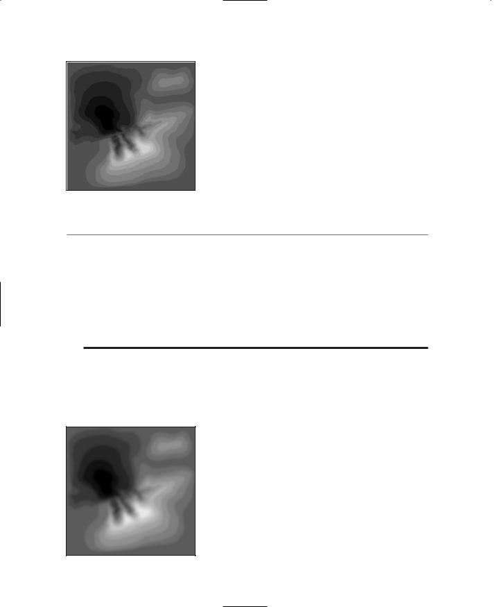
Figure 12.2 depicts a height map. As you can see, it's a grayscale image. The 2D coordinates of the height-map image map directly to surface coordinates in the game world. The brightness off each of the pixels in the image represents the altitude at that pixel's loca- tion—the brighter the pixel, the higher the elevation. Usually we use an 8-bit per pixel format, which means that 256 discrete elevations can be represented.
The concept is an elegant one and not difficult to grasp. If you are familiar with viewing topographic charts and maps, you'll find that height maps have a familiar flavor to them, even though the contour lines are missing. One of the deficiencies of height maps is the resolution (as you can see in Figure 12.2). To represent a geographic locale that is 1 kilometer square, a height map that represents 1 square meter as a pixel needs 1,000 pixels per side, for a total of 1 million pixels—big, but not too large. If I want to increase the terrain area to
cover 16 square kilometers (4 meters per side), then I need to store 16 million pixels. At 8 bits per pixel, that equals about 16MB of data. If we want to model the terrain for an area that is 10 kilometers per side, we are looking at 100MB of storage!
|
We can, of course, reduce the terrain resolution— |
|
let's say, have a pixel equal 4 square meters in the |
|
game world. This would chop those 100MB back to |
|
6.25MB. However, that gain is offset by the fact that |
|
our terrain will now be blockier and less realistic. |
|
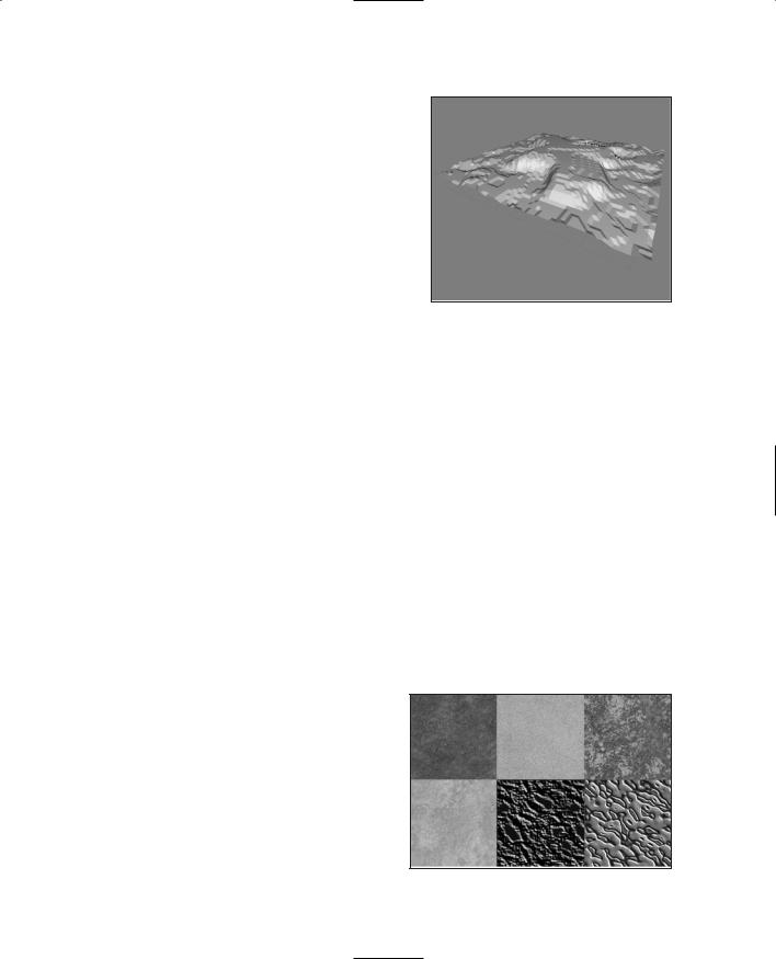
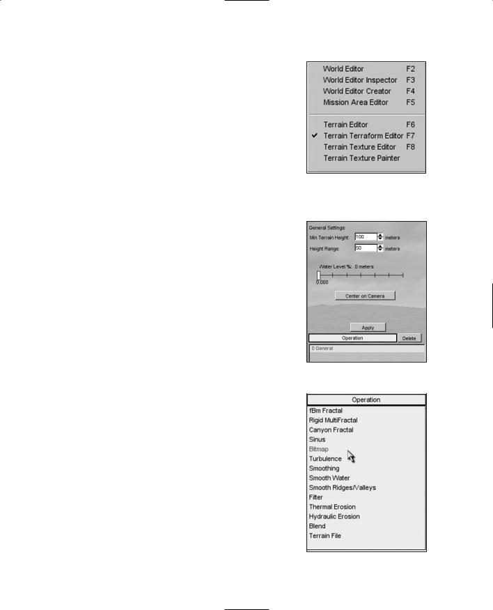
Figure 12.3 shows a terrain model generated from |
|
the height map shown in Figure 12.2. In this case |
|
MilkShape was used to import the height map and |
Figure 12.2 A terrain height map. |
create the terrain object. |
Team LRN
Terrain Modeling |
369 |
Terrain Cover
In the simplest sense, terrain cover refers to all the stuff that you find on the ground, including:
■grass
■flowers
■dirt
■pebbles
■rocks
■trash
■litter
■pavement
■concrete
■moss
■sand
■stone
Figure 12.3 A terrain created from a height map.
Obviously this is not a comprehensive list, but it does demonstrate the point.
We represent the terrain cover with textures. Our options for creating these textures are much like those we considered when we created textures for structures in Chapter 11— and the factors that dictate which way to choose are also similar. It boils down to the terrain characteristics in the game that matter to you.
We can also mix terrain cover textures in adjacent areas to portray a particular locale. It's a good idea to develop your own library of generic terrain cover for use in various situations.
Figure 12.4 illustrates some of the possible varieties of terrain cover. From left to right in the top row you can see grass, sand, and an intermixed sand and grass texture. In the bottom row from left to right are dirt, a muddy track, and eroded wet sand.
Tiling
Unless you are going to create specific terrain cover textures for every square inch of terrain, you will end up tiling your terrain cover at some point. All the issues brought up with tiling in other contexts apply here, such as matching texture edges to get seamless transitions and ensuring lighting in the textures is
both appropriate and uniform. Additionally, Figure 12.4 Some example terrain textures.
Team LRN
370Chapter 12 ■ Terrains
you should ensure that there are no patterns or marks in the texture that will stand out too much when the texture is repeated.
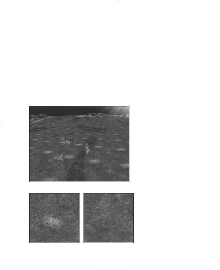
In Figure 12.5 you can see a repeating light pattern that tends to overpower the otherwise pleasing and pastoral scene. (Okay, okay, it would be pastoral if a storm wasn't brewing beyond the, um…Mountains of Evil in the distance. But besides that…)
The culprit in this case is the grass texture used, which is shown in Figure 12.6.
Notice the area of lighter grass, which is quite noticeably different from the rest of the image. When repeated over and over across large swaths of terrain, that feature detracts from the intended overall effect. We can enhance the image to minimize the problem, perhaps with something like that shown in Figure 12.7.
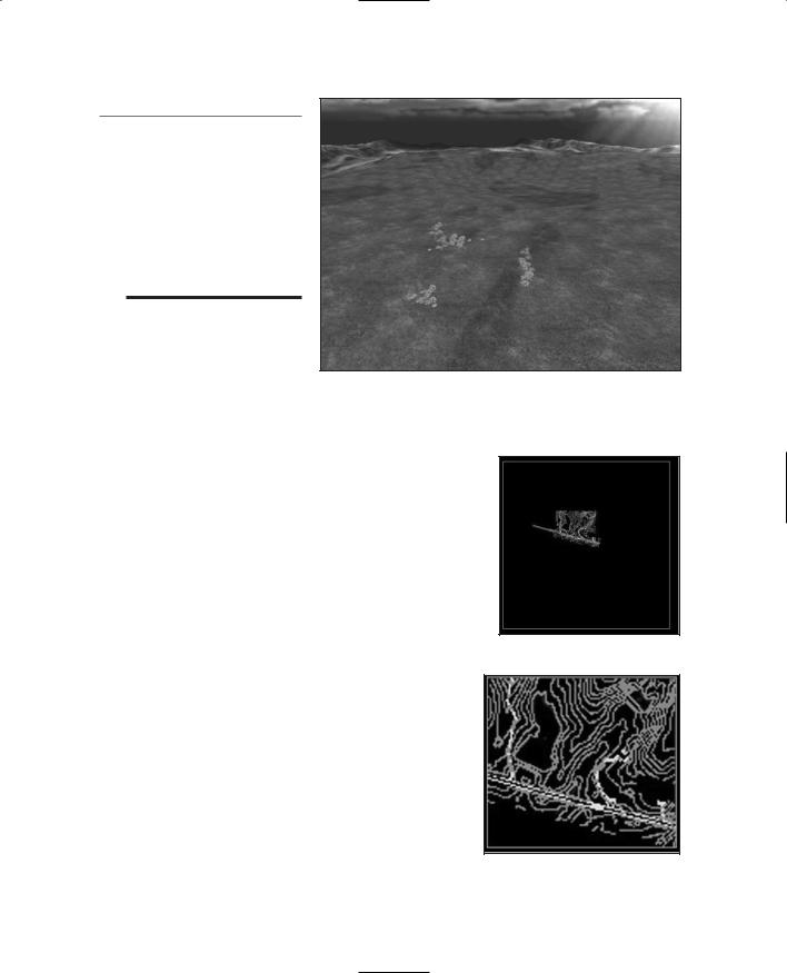
The result is dramatic and the difference is quite obvious, as you can see in Figure 12.8. Now, I confess that the texture could be better, but you have to admit that it is light-years
ahead of the first version, shown in Figures 12.5 and 12.6.
|
Creating Terrains |
|
|
Okay, enough talk. Time for |
|
|
some action—let's create some |
|
|
terrain. We'll use the Torque |
|
|
Engine and its internal Terrain |
|
|
Manager to create the terrain, |
|
|
and we'll employ the height- |
|
|
map method using the in- |
|
|
game Terrain Editor. There is |
|
|
another method, direct manip- |
|
|
ulation, that we'll use later in |
|
Figure 12.5 A terrain with tiling artifacts. |
||
Chapter 18. |
||
|
Figure 12.6 A texture with an undesirable feature.
Figure 12.7 A texture without the undesirable feature.
The Height-Map
Method
For this section, you will need to fire up Paint Shop Pro. You should be fairly familiar with the basics, so I won't hold your hand too much with respect to PSP operations.
Team LRN
Creating Terrains |
371 |
n o t e
The default size for a terrain in Torque (when the squareSize property in a MIS mission file is set to 8) is 65,536 world units (WU).
One WU in Torque is equal to one unit in most third-party map editors. A WU is equivalent to one scaled inch.
1.Start with a drawing of the contours to create the height-map image.
Figure 12.8 The terrain with improved tiled texture.
If you have a source for
colored contour drawings for a section of land drawn at full scale (1:1), such as shown in Figure 12.9, get one that suits your needs. If not, you can use the images shown here, but in their colored format, which you will find
at C:\3DGPAi1\RESOURCES\CH12. Each image has the same name as the figure number used here.
2.Clip out the portion you want and save it as a PNG image, as shown in Figure 12.10.
3.Now you need to do a little noodling over scale and unit numbers.
In Torque each terrain square is made of two terrain
triangles sized at 256 WU by 256 WU; as mentioned
earlier, the default squareSize property in a Torque Figure 12.9 Contour map. mission file equals 8 by default. The terrain has
256 of these squares per side for a total of 65,536 world units (inches) per side.
256 WU 256 squares=65,536 WU (inches)
If we convert the units, we get 5,641.3 feet, or 1,664.6 meters (1.034 miles, or 1.6646 kilometers).
65,536 inches 12 inches=5,461.33 feet
1 mile=5,280 feet
5,461.33 feet 5,280 feet per mile=1.034 miles
1 mile=1,609 meters
1,664.6177 meters 1,609 meters per mile=1.034 miles
Figure 12.10 Cropped and resized contour map.
Team LRN

372 Chapter 12 ■ Terrains
The value 8 (for squareSize) and the value 65,536 (for terrain size) are not accidental; they are powers of 2. This works nicely with our images as well as the software. The size for our height-map image must be 256 pixels by 256 pixels. This means that when the image is stretched to fit our terrain of 65,536 inches by 65,536 inches, each texture pixel (texel) determines the horizontal distance of 256 inches (or 6.504 meters) of terrain. Because each terrain square is 256 WU, each heightmap texel is used to determine the height of one terrain square.
256 pixels 256 WU (inches)=65,536 WU (inches)
256 inches 39.37 inches per meter=6.5024 meters
6.5024 meters 256 pixels=1,664.6177 meters=1.664 kilometers=1.034 miles
4.Based on the preceding calculations, we can get the equivalent area in the image— crop the image just inside the line box created in the Figure 12.10 drawing representing 1.034 square miles.
5.Resize the image to 256 by 256 pixels.
6.Save the image as a PNG file to preserve the original colors for the contours.
In a moment you will paint over this contour image using gray color values representing the heights of the contour lines. In this case the contours range from an elevation of 410 feet to 485 feet. This information is available from the source of the contour maps. The grayscale can be any sequence of gray RGB values within the 256 colors ranging from 0,0,0 (black) to 255,255,255 (white).
7.Establish your scale, keeping in mind that it's best to have some separation between the incremental values so they can be easily seen as you paint the contours.
Examination reveals that there are 16 elevation increments in the contour range of 410 to 485. Divide the 256 colors for the grayscale range by 16, and you will get the values in Table 12.2, which starts at the color (0,0,0) and works up.
Now that we have the values, we need to create what Paint Shop Pro calls swatches. We need to make a different swatch for each increment.
8.Make sure that you have the Materials palette visible in Paint Shop Pro by choosing View, Palettes, Materials and clicking on the Swatches tab in the Materials frame.
9.Delete any existing swatches by clicking on each one and then clicking on the trash can icon below the swatches. If you think you can keep track of your custom swatches and the ones already there, then you can skip this step.
Next we will create a new swatch for our first increment.
1.Click the Create New Swatch button at the bottom of the Swatch frame.
2.Type in a name for your swatch. I suggest you use either the increment number or the elevation value for the name. You could also use both, as in 1-485 for the topmost entry from Table 12.2.
Team LRN
Creating Terrains |
373 |
Table 12.2 Elevation RGB Values
Elevation |
RGB |
Increment |
485 |
240,240,240 |
1 |
480 |
224,224,224 |
2 |
475 |
208,208,208 |
3 |
470 |
192,192,192 |
4 |
465 |
176,176,176 |
5 |
460 |
160,160,160 |
6 |
455 |
144,144,144 |
7 |
450 |
128,128,128 |
8 |
445 |
112,112,112 |
9 |
440 |
96, 96, 96 |
10 |
435 |
80, 80, 80 |
11 |
430 |
64, 64, 64 |
12 |
425 |
48, 48, 48 |
13 |
420 |
32, 32, 32 |
14 |
415 |
16, 16, 16 |
15 |
410 |
0, 0, 0 |
16 |
3.The Color dialog box will appear. Here you type in your RGB values, referring to Table 12.2 for your numbers. Click OK to close the dialog box.
4.Repeat steps 1, 2, and 3 for each increment in the table.
5.Now fill in your image following the contour lines as shown in Figure 12.11. Use a combination of the Brush and Fill tools, at your discretion, to complete the task.
Notice that in Figure 12.11 the grayscale value is the same at all the edges. This is because we want the edges to match when the terrain repeats itself, if it is tiled— and in this case that's what we will be dealing
with. The edges could be different values; you would then just match them at the top and bottom or left and right sides.
6.When you have finished the "paint-by-number" process, convert the image to grayscale by choosing Image, Grayscale.
7.Save your image as a PNG file.
8.Flip the image around its X-axis—this flips the top with the bottom—by choosing Image, Flip.
You should get an image like that in Figure |
Figure 12.11 Contour map with |
|
12.12. Make sure you save your work. |
||
grayscale values. |
Team LRN
374 Chapter 12 ■ Terrains
Figure 12.12 Terraced height map.
t i p
Notice the terrace effect in Figure 12.12. If you import this into Torque as is, you will have a set of terraced, or stepped, surfaces. If this is what you want, then you're good to go already. However, let's go a bit farther.
9.Make a copy of the image you created in step 7 to work with.
10.Choose Adjust, Blur, Gaussian Blur to smooth out the edges a bit. Use a radius of four and then save your changes to this new image as a PNG file. You should get an image much like the one shown in Figure 12.13.
It can be more difficult to locate your original contour features after smoothing with Gaussian Blur. A quick work-around is to try reducing the radius or use the original image unblurred and smooth the terrain in Torque using the Terrain Editor (covered later).
A more time-consuming technique (but much more accurate and rewarding) is to create the terrain image at a much larger scale and reduce it to 256 by 256. For example, you might try constructing the image at around 2,048 by 2,048 or 4,096 by 4,096; this means much more painting time, but after reducing the image size again, the blending information is retained (although somewhat smoothed) by the resize algorithms. The resulting terrain is much more accurate than the Gaussian Blur process.
This last height-map image is the one you will work with to create the terrain.
Next, we will import these images into Torque.
11.Place the images in Torque's C:\3DGPAi1\common\editor\heightscripts folder. If the folder does not already exist, create it.
12.Use the Run fps Demo shortcut to launch Torque.
13.Run any existing mission to which you'd like to add this terrain or choose File, New Mission.
14.Press F11 to open the World and Terrain Editor.
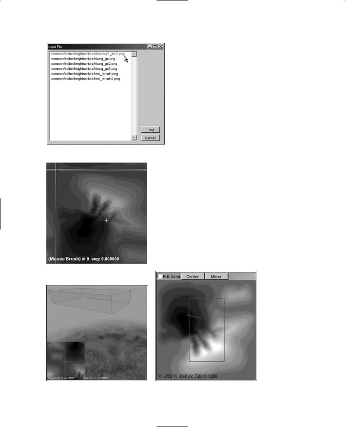
15.Choose Window, Terrain Terraform Editor (as shown in Figure 12.14) to open the
Terrain Terraform Editor.
16.On the right side of the screen, in the General Settings area (see Figure 12.15), set Min
Figure 12.13 Blurred height map. Terrain Height and Height Range in meters.
Team LRN
The maximum elevation in the terrain we are modeling is to be used for Minimum Terrain Height (the Minimum Terrain Height box is mislabeled in the Editor). You will recall that the highest elevation is 485 feet; this translates to a Minimum Terrain Height value of approximately 148 meters.
485 feet 3.281 feet per meter=147.8208 (148) meters
Height Range represents the distance from our lowest to highest elevation. The grayscale color values of our height-map image will be interpolated between these values. We need to calculate the difference and multiply that by the ratio of highest color number divided by total number of grayscale colors (256) and convert to meters. Clear as mud?
485 feet 410 feet=75 feet
240 256 75 feet=70.3 feet (240 is our highest color number in
Table 12.2)
70.3feet 3.281 feet per meter=21.4 (21) meters
17.Now click the Operation box to roll out the Operation dialog box, as shown in Figure 12.16.
18.Select Bitmap from this dialog box—this brings up a bitmap Load File dialog box, as shown in Figure 12.17.
19.Highlight the image you want translated to a new terrain and click the Load button. You should find the height-map image you saved earlier in C:\3DGPAi1\common\editor\heightscripts, from Paint Shop Pro.
20.Click the Apply button at the right side of the menu. You will see the terrain change. To relight the scene, choose Edit, Relight Scene. There will be a slight pause in input response while the relighting occurs.
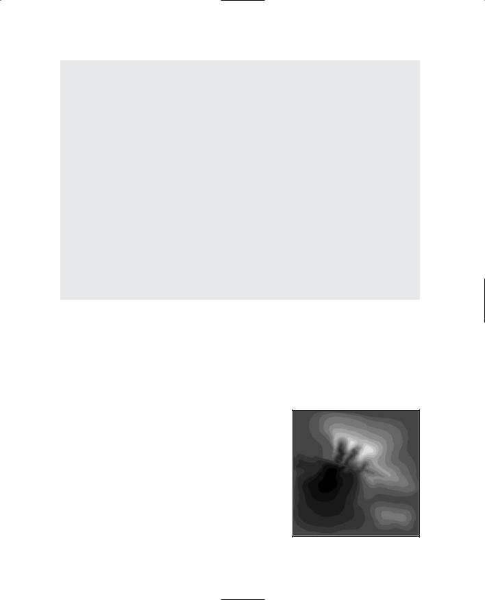
21.In the lower left of the screen the overhead map view of the terrain will change to show the contours imported from the height-map image.
Notice that this image, as depicted in Figure 12.18, has the same orientation as the original one before we flipped it around the X-axis in step 8 of this list.
Creating Terrains |
375 |
Figure 12.14 World Editor
Window menu with Terrain
Terraform Editor checked.
Figure 12.15 Terraform Editor.
Figure 12.16 The Operation dialog box.
Team LRN
376 |
Chapter 12 |
■ Terrains |
|
|
|
|
|
|
|
|
The white line in the map shows the |
|
|
|
|
|
|
|
|
|
|
|
terrain boundary, representing the |
|
|
|
|
|
extents of your terrain before repeat- |
|
|
|
|
|
ing. In the main 3D view, a green |
|
|
|
|
|
translucent box illustrates this bound- |
|
|
|
|
|
ary, as you can see in Figure 12.19. The |
|
|
|
|
|
terrain boundary is a fixed dimen- |
|
|
|
|
|
sion—you can't change it. |
|
|
|
|
|
Figure 12.20 illustrates where to find |
|
|
|
|
|
the inner red box that represents the |
|
|
|
|
|
mission area. You can change the |
|
|
|
|
|
extents of the mission area boundary by |
|
Figure 12.17 |
The Load File dialog box. |
|
||
|
|
using the Mission Editor. |
|||
|
|
|
|
|
|
|
|
|
|
|
22. Choose File, Save As to save your mis- |
|
|
|
|
|
|
|
|
|
|
|
sion with your own unique name. You |
|
|
|
|
|
should save your new file in the direc- |
|
|
|
|
|
tory C:\3DGPAi1\fps\data\missions. |
|
|
|
|
When you save your mission, the terrain data is also |
|
|
|
|
|
saved as a TER file in the C:\3DGPAi1\fps\data\mis- |
|
|
|
|
|
sions directory. If you want, you can also import |
|
|
|
|
|
previously saved TER files rather than re-creating |
|
|
|
|
|
height maps. |
|
|
|
|
|
|
|
Figure 12.18 The overhead view.
Figure 12.19 The terrain boundary. |
Figure 12.20 The mission area. |
Team LRN

Creating Terrains |
377 |
n o t e
Reference to the newly created terrain file is stored in the mission file in a TerrainBlock that needs to be named "Terrain":
new TerrainBlock(Terrain) { rotation = "1 0 0 0"; scale = "1 1 1";
detailTexture = "~/data/terrains/details/detail1"; terrainFile = "./myterrain.ter";
squareSize = "8"; locked = "true";
position = "-1024 -1024 0";
};
Establishing Terrain Sizes
The units displayed in the Mission Editor map (x, y, w, h) represent the (x,y) distance of the upper-left corner of the mission area (in red) from the image center and the (w,h) width and height of the area in terrain texture units. Note that the position parameter in the mission file also uses the terrain texture units to position one terrain repetition. There are 32 repetitions of the terrain textures (don't confuse these with the height-map images) with each terrain texture image being 256 by 256 pixels.
32 reps 256 pixels=2,048 texture units
65,536 WU 2,048 texture units=32 WU per texel
This information will be useful when creating terrain textures. Convert these values to inches by multiplying by 32. (The total area represented ranges from 1,024 to +1,024 when the terrain squareSize=8 for a total 2,048. And 2,048 32=65,536.)
If your contour area needs to be other than 1.034 miles, you can change the terrain squareSize. This will determine the area available before the terrain repeats. As you can see in Table 12.3, you must adjust the squareSize parameter in powers of 2.
|
Table 12.3 |
Terrain Sizes |
|
|
|
|
|
|
Terrain |
Texels +/ , |
Texels 32 = WU |
Feet |
Miles |
Meters |
|
|
SquareSize |
total |
|
|
|
|
|
32 |
+ 4,096=8192 |
8,192 32=262,144 |
21,845.33 |
4.137 |
6,658.13 |
|
|
16 |
+ 2,048=4,096 |
4,096 32=131,072 |
10,922.66 |
2.068 |
3,329.06 |
|
|
8 |
+ 1,024=2,048 |
2,048 32=65,536 |
5,461.33 |
1.034 |
1,664.53 |
|
|
4 |
+ 512=1,024 |
1,024 32=32,768 |
2,730.66 |
0.517 |
832.26 |
|
|
2 |
+ 256=512 |
512 32=16,384 |
1,365.33 |
0.258 |
416.13 |
|
|
|
|
|
|
|
|
|
|
Team LRN