

Doicu A., Wriedt T., Eremin Y.A. Light scattering by systems of particles (OS 124, Springer, 2006
.pdf3.7 Composite Particles |
239 |
z |
r |
|
|
|
l |
|
L |
z1 |
|
|
x |
z3 |
|
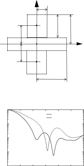
Fig. 3.62. Geometry of a composite particle consisting of three identical cylinders
characteristics can be computed with localized or distributed sources, and the program supports calculations for dielectric particles. Particle geometries included in the library are half-spheroids with o set origins and three cylinders.
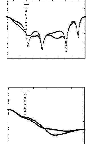
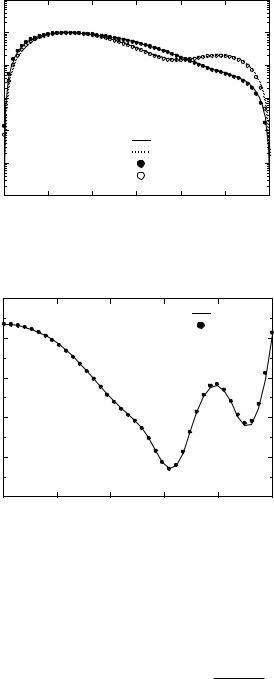
In Fig. 3.62, we show a composite particle consisting of three identical cylinders of radius ksr = 2 and length ksl = 4. The axial positions of the first and third cylinder are given by ksz1 = 4 and ksz3 = −4, and the relative refractive indices are chosen as mr1 = mr3 = 1.5 and mr2 = 1.0. Because mr2 = 1.0, the scattering problem is equivalent to the multiple scattering problem of two identical cylinders. On the other hand, the composite particle can be regarded as an inhomogeneous cylinder with a cylindrical inclusion. Therefore, the scattering characteristics are computed with three independent routines: TCOMP, TMULT, and TLAY. Localized and distributed sources are used for T -matrix calculations with the TCOMP routine, while distributed sources are used for calculations with the TLAY routine. Figure 3.63 shows the di erential scattering cross-sections for a fixed orientation of the composite particle (αp = βp = 45◦), while Fig. 3.64 illustrates the numerical results for a random orientation. The behavior of the far-field patterns are quite similar.
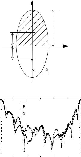
In order to demonstrate the capability of the code to compute the electromagnetic scattering by composite particles with elongated and flattened regions, we consider the geometry depicted in Fig. 3.65. For this application, the sources are distributed on the real and imaginary axes. The parameters specifying the particle shape are: ksr = 1, ksR = 3, ksl = 6 and ksL = 7, while the relative refractive indices are identical mr1 = mr2 = mr3 = 1.5. For the prolate cylinders, Nrank = 10 sources are distributed along the axis of symmetry, and for the oblate cylinder, Nrank = 10 sources are distributed


3.7 Composite Particles |
241 |
z r
l |
L |
z1 |
x |
|
|
z3 |
|
R
Fig. 3.65. Geometry of a composite particle consisting of three cylinders
|
10−1 |
|
|
|
|
|
|
|
|
|
|
|
|
|
TCOMP - parallel |
|
|
|
|
|
|
|
|
TCOMP - perpendicular |
|
|
|
10−2 |
|
|
|
|
|
|
|
DSCS |
10−3 |
|
|
|
|
|
|
|
|
|
|
|
|
|
|
|
|
|
10−4 |
|
|
|
|
|
|
|
|
10−5 |
0 |
30 |
60 |
90 |
120 |
150 |
180 |
Scattering Angle (deg)
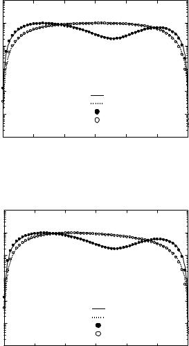
Fig. 3.66. Normalized di erential scattering cross-sections of a composite particle consisting of three cylinders

|
|
3.8 Complex Particles |
243 |
|
Table 3.7. Parameters of calculation for a composite spheroid |
|
|||
|
|
|
|
|
Type of sources |
Nrank-half-spheroid |
Nrank-composite particle |
Nint |
|
|
|
|
|
|
Localized |
22 |
34 |
1000 |
|
Distributed |
18 |
32 |
1000 |
|
|
|
|
|
|
Z 
mr1,1
O1
z1
mr1,2
x2 O |
X |
mr2,1 |
x1 |
mr2,2 |
mr |
z2 |
|
O2 |
|
Fig. 3.69. Geometry of an inhomogeneous sphere containing a composite and a layered spheroid as separate inclusions
refractive index mr = 1.2, while the wavelength of the incident radiation is λ = 0.628 µm. The inhomogeneities are a composite and a layered prolate spheroid. The composite particle consists of two identical half-spheroids with semi-axes a1 = 0.3 µm and b1 = 0.2 µm, and relative refractive indices (with respect to the ambient medium) mr1,1 = 1.5 and mr1,2 = 1.33. The layered particle consists of two concentric prolate spheroids with semi-axes a2,1 = 0.3 µm, b2,1 = 0.2 µm, and a2,2 = 0.15 µm, b2,2 = 0.1 µm, and relative refractive indices mr2,1 = 1.5 and mr2,2 = 1.8. The position of the composite particle with respect to the global coordinate system of the host particle is specified by the Cartesian coordinates x1 = y1 = z1 = 0.3 µm, while the Euler orientation
angles are αp1 = βp1 = 45◦. For the layered particle, we choose x2 = y2 = z2 = −0.3 µm and αp2 = βp2 = 0◦.
The results plotted in Fig. 3.70 are computed with the TMULT routine and show the di erential scattering cross-sections for the two-spheroid system. The particles are placed in a medium with a refractive index of 1.2, and the

244 3 Simulation Results
|
−1.00 |
|
|
|
|
|
|
|
|
10 |
|
|
|
TMULT - parallel |
|
|
|
|
|
|
|
|
|
|
||
|
−2.00 |
|
|
|
TMULT - perpendicular |
|
|
|
|
|
|
|
|
|
|
|
|
|
10 |
|
|
|
|
|
|
|
|
−3.00 |
|
|
|
|
|
|
|
DSCS |
10 |
|
|
|
|
|
|
|
−4.00 |
|
|
|
|
|
|
|
|
|
10 |
|
|
|
|
|
|
|
|
−5.00 |
|
|
|
|
|
|
|
|
10 |
|
|
|
|
|
|
|
|
−6.00 |
|
|
|
|
|
|
|
|
10 |
0 |
60 |
120 |
180 |
240 |
300 |
360 |
|
|
|||||||
Scattering Angle (deg)
Fig. 3.70. Normalized di erential scattering cross-sections of a composite and a layered particle
|
102 |
|
|
|
|
|
|
|
101 |
|
|
TINHOM - parallel |
|
|
|
|
|
|
TINHOM - perpendicular |
|
|||
|
100 |
|
|
|
|
|
|
DSCS |
10−1 |
|
|
|
|
|
|
10−2 |
|
|
|
|
|
|
|
10−3 |
|
|
|
|
|
|
|
|
|
|
|
|
|
|
|
|
10−4 |
|
|
|
|
|
|
|
10−5 |
|
|
|
|
|
|
|
10−6 |
60 |
120 |
180 |
240 |
300 |
360 |
|
0 |
||||||
Scattering Angle (deg)
Fig. 3.71. Normalized di erential scattering cross-sections of an inhomogeneous sphere. The inclusion consists of a composite and a layered particle
dimension of the system T -matrix is given by Nrank = 14 and Mrank = 12. The incident wave travel along the Z-axis of the global coordinate system and the angular scattering is computed in the azimuthal plane ϕ = 0◦. The system T -matrix serves as input parameter for the TINHOM routine. The resulting T -matrix is characterized by Nrank = 16 and Mrank = 14, and corresponds to a sphere containing a composite and a layered spheroid as separate inclusions. Figure 3.71 illustrates the di erential scattering crosssections for the inhomogeneous sphere in the case of normal incidence.

3.9 Particle on or Near a Plane Surface |
245 |
3.9 Particle on or Near a Plane Surface
In this section, we present scattering results for an axisymmetric particle situated on or near a plane surface. For this purpose we use the TPARTSUB routine and a computer program based on the discrete sources method [59,60].
Figures 3.72–3.74 show the di erential scattering cross-sections for Fe-, Siand SiO-spheroids with semi-axes a = 0.05 µm and b = 0.025 µm. The relative refractive indices are: mr = 1.35 + 1.97j for Fe, mr = 4.37 + 0.08j for
|
1 |
|
|
|
|
|
|
|
10 |
|
|
|
|
|
|
|
0 |
|
|
|
|
|
|
|
10 |
|
|
|
|
|
|
|
−1 |
|
|
|
|
|
|
|
10 |
|
|
|
|
|
|
|
−2 |
|
|
|
|
|
|
DSCS |
10 |
|
|
|
|
|
|
−3 |
|
|
|
|
|
|
|
10 |
|
|
|
|
|
|
|
|
|
|
|
|
|
|
|
|
−4 |
|
|
|
TPARTSUB - parallel |
|
|
|
10 |
|
|
|
TPARTSUB - perpendicular |
|
|
|
|
|
|
|
|
||
|
−5 |
|
|
|
DSM - parallel |
|
|
|
10 |
|
|
|
DSM - perpendicular |
|
|
|
−6 |
|
|
|
|
|
|
|
10 90 |
120 |
150 |
180 |
210 |
240 |
270 |
Scattering Angle (deg)
Fig. 3.72. Normalized di erential scattering cross-sections of a Fe-spheroid computed with the TPARTSUB routine and the discrete sources method (DSM)
|
|
1 |
|
|
|
|
|
|
|
10 |
|
|
|
|
|
|
|
|
|
0 |
|
|
|
|
|
|
|
10 |
|
|
|
|
|
|
|
|
10 |
−1 |
|
|
|
|
|
|
|
|
|
|
|
|
|
|
|
DSCS |
10 |
−2 |
|
|
|
|
|
|
|
|
|
|
|
|
|
||
10 |
−3 |
|
|
|
|
|
|
|
|
|
|
|
|
|
|
||
|
|
|
|
|
|
|
|
|
|
10 |
−4 |
|
|
|
TPARTSUB - parallel |
|
|
|
|
|
|
|
|
|||
|
|
|
|
|
|
TPARTSUB - perpendicular |
|
|
|
10 |
−5 |
|
|
|
DSM - parallel |
|
|
|
|
|
|
|
DSM - perpendicular |
|
||
|
|
|
|
|
|
|
||
|
10 |
−6 |
|
|
|
|
|
|
|
90 |
120 |
150 |
180 |
210 |
240 |
270 |
|
Scattering Angle (deg)
Fig. 3.73. Normalized di erential scattering cross-sections of a Si-spheroid computed with the TPARTSUB routine and the discrete sources method (DSM)

246 3 Simulation Results
|
1 |
|
|
|
|
|
|
|
10 |
|
|
|
|
|
|
|
0 |
|
|
|
|
|
|
|
10 |
|
|
|
|
|
|
|
−1 |
|
|
|
|
|
|
|
10 |
|
|
|
|
|
|
|
−2 |
|
|
|
|
|
|
DSCS |
10 |
|
|
|
|
|
|
−3 |
|
|
|
|
|
|
|
10 |
|
|
|
|
|
|
|
|
|
|
|
|
|
|
|
|
−4 |
|
|
|
TPARTSUB - parallel |
|
|
|
10 |
|
|
|
|
||
|
|
|
|
|
TPARTSUB - perpendicular |
||
|
−5 |
|
|
|
DSM - parallel |
|
|
|
10 |
|
|
|
DSM - perpendicular |
|
|
|
|
|
|
|
|
||
|
−6 |
|
|
|
|
|
|
|
10 90 |
120 |
150 |
180 |
210 |
240 |
270 |
Scattering Angle (deg)
Fig. 3.74. Normalized di erential scattering cross-sections of a SiO-spheroid computed with the TPARTSUB routine and the discrete sources method (DSM)
Si, and mr = 1.67 for SiO. The particles are situated on a silicon substrate, the wavelength of the incident radiation is λ = 0.488 µm, and the incident angle is β0 = 45◦. The plotted data show that the T -matrix method leads to accurate results.
In the next example, we investigate scattering of evanescent waves by particles situated on a glass prism. We note that evanescent wave scattering is important in various sensor applications such as the total internal reflection microscopy TIRM [195]. Choosing the wavelength of the external excitation as λ = 0.488 µm and taking into account that the glass prism has a refractive index of mrs = 1.5, we deduce that the evanescent waves appear for incident angles exceeding 41.8◦. In Figs. 3.75–3.77, we plot the di erential scattering cross-section for Ag-, diamond-, and Si-spheres with a diameter of d = 0.2 µm. The relative refractive indices of Agand diamond particles are mr = 0.25 + 3.14j and mr = 2.43, respectively. The scattering plane coincides with the incident plane and the angle of incidence is β0 = 60◦. The plotted data show a good agreement between the discrete sources and the T -matrix solutions.
3.10 E ective Medium Model
The e ective wave number of a half-space with randomly distributed spheroidal particles can be computed with the EFMED routine.
First we consider spherical particles and compare our results to the solutions obtained with the Matlab program QCAMIE included in the Electro-
3.10 E ective Medium Model |
247 |
|
1 |
|
|
|
|
|
|
|
10 |
|
|
|
|
|
|
|
0 |
|
|
|
|
|
|
|
10 |
|
|
|
|
|
|
|
−1 |
|
|
|
|
|
|
|
10 |
|
|
|
|
|
|
DSCS |
−2 |
|
|
|
|
|
|
10 |
|
|
|
|
|
|
|
|
|
|
|
|
|
|
|
|
−3 |
|
|
|
|
|
|
|
10 |
|
|
|
TPARTSUB - parallel |
|
|
|
|
|
|
|
TPARTSUB - perpendicular |
|
|
|
−4 |
|
|
|
DSM - parallel |
|
|
|
10 |
|
|
|
DSM - perpendicular |
|
|
|
|
|
|
|
|
||
|
−5 |
|
|
|
|
|
|
|
10 90 |
120 |
150 |
180 |
210 |
240 |
270 |
Scattering Angle (deg)
Fig. 3.75. Normalized di erential scattering cross-sections of a metallic Ag-sphere computed with the TPARTSUB routine and the discrete sources method (DSM)
|
1 |
|
|
|
|
|
|
|
10 |
|
|
|
|
|
|
|
0 |
|
|
|
|
|
|
|
10 |
|
|
|
|
|
|
|
−1 |
|
|
|
|
|
|
|
10 |
|
|
|
|
|
|
DSCS |
−2 |
|
|
|
|
|
|
10 |
|
|
|
|
|
|
|
|
|
|
|
|
|
|
|
|
−3 |
|
|
|
|
|
|
|
10 |
|
|
|
TPARTSUB - parallel |
|
|
|
|
|
|
|
|
||
|
−4 |
|
|
|
TPARTSUB - perpendicular |
||
|
10 |
|
|
|
DSM - parallel |
|
|
|
|
|
|
|
DSM - perpendicular |
|
|
|
−5 |
|
|
|
|
|
|
|
10 90 |
120 |
150 |
180 |
210 |
240 |
270 |
Scattering Angle (deg)
Fig. 3.76. Normalized di erential scattering cross-sections of a Diamond-sphere computed with the TPARTSUB routine and the discrete sources method (DSM)
magnetic Wave Matlab Library and available from www.emwave.com. This library contains several Matlab programs which are based on the theory given in the book of Tsang et al. [229]. Figures 3.78 and 3.79 show the normalized phase velocity ks/Re{Ks} and the e ective loss tangent 2Im{Ks}/Re{Ks} as functions of the size parameter x = ksR, and it is apparent that no substantial di erences between the curves exist.
248 3 Simulation Results
|
1 |
|
|
|
|
|
|
|
10 |
|
|
|
|
|
|
|
0 |
|
|
|
|
|
|
|
10 |
|
|
|
|
|
|
|
−1 |
|
|
|
|
|
|
|
10 |
|
|
|
|
|
|
DSCS |
−2 |
|
|
|
|
|
|
10 |
|
|
|
|
|
|
|
|
|
|
|
|
|
|
|
|
−3 |
|
|
|
|
|
|
|
10 |
|
|
|
TPARTSUB - parallel |
|
|
|
|
|
|
|
|
||
|
−4 |
|
|
|
TPARTSUB - perpendicular |
||
|
|
|
|
DSM - parallel |
|
|
|
|
10 |
|
|
|
|
|
|
|
|
|
|
|
DSM - perpendicular |
|
|
|
−5 |
|
|
|
|
|
|
|
10 90 |
120 |
150 |
180 |
210 |
240 |
270 |
Scattering Angle (deg)
Fig. 3.77. Normalized di erential scattering cross-sections of a Si-sphere computed with the TPARTSUB routine and the discrete sources method (DSM)
|
0.89 |
|
|
|
|
|
|
|
|
|
|
EFMED |
|
|
|
|
|
|
QCAMIE |
|
|
0.88 |
|
|
|
|
|
Velocity |
0.87 |
|
|
|
|
|
|
|
|
|
|
|
|
Phase |
0.86 |
|
|
|
|
|
|
|
|
|
|
|
|
|
0.85 |
|
|
|
|
|
|
0.84 |
|
|
|
|
|
|
0.0 |
0.5 |
1.0 |
1.5 |
2.0 |
2.5 |
Size Parameter
Fig. 3.78. Normalized phase velocity versus size parameter computed with the EFMED routine and the Matlab program QCAMIE
Next we consider the test examples given by Neo et al. [179] and compare the T -matrix results to the solutions obtained with the long-wavelength quasicrystalline approximation
# |
|
3c εr−1 |
|
|
2x |
3 |
|
|
εr−1 |
|
(1 − c) |
4 + |
||
Ks2 = ks2 1 + |
|
|
εr+2 |
|
1 + j |
|
|
|
εr+2 |
|
|
|||
|
|
c εr−1 |
|
3 1 |
|
c εr−1 |
(1 + 2c)2 |
|||||||
1 |
− |
|
|
− |
|
|||||||||
|
|
εr+2 |
|
|
|
|
|
|
εr+2 |
|
|
|
||