

|
|
|
Chapter 3 - Fundamental PLC Programming |
|
| |
IN1 |
IN2 |
OUT1 |
|
1--- |
| | |
------- | | --------------------------------------------------------- |
(OUT)| |
|
| |
|
|
|
|
| |
|
|
|
|
| |
IN1 |
|
OUT2 |
|
| |
|
|||
2--- |
| | |
------------------------------------------------------------------- | |
(OUT)| |
|
| |
IN2 |
|
|
|
|--- |
| |--- |
+ |
|
|
| |
|
|
|
|
| |
|
|
|
|
| |
IN1 |
IN2 |
OUT3 |
|
| |
||||
3--- |
| |------- --------------------------------------------------------- |
| | |
(OUT)| |
|
| |
IN3 |
IN4 |
| |
|
|--- |
| |------- --- |
| | |
+ |
|
| |
|
|
|
|
| |
|
|
|
|
| |
IN1 |
IN3 |
OUT4 |
|
| |
||||
4--- |
| |------- --------------------------------------------------------- |
| | |
(OUT)| |
|
| |
IN2 |
| IN4 |
| |
|
|--- |
| |------- --- |
| | |
+ |
|
| |
|
|
|
|
Figure 3-8 - PLC Program with AND-OR and OR-AND Added
3-4. Example Problem 1
A lighting control system is to be developed. The system will be controlled by four switches, SWITCH1, SWITCH2, SWITCH3, and SWITCH4. These switches will control the lighting in a room based on the following criteria:
1.Any of three of the switches SWITCH1, SWITCH2, and SWITCH3, if turned ON can turn the lighting on, but all three switches must be OFF before the lighting will turn OFF.
2.The fourth switch SWITCH4 is a Master Control Switch. If this switch is in the ON position, the lights will be OFF and none of the other three switches have any control.
Problem: |
Design the wiring diagram for the controller connections, assign the inputs |
|
and outputs and develop the ladder diagram which will accomplish the task. |
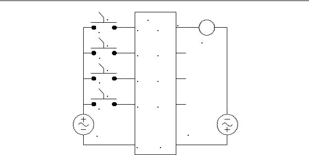
The first item we may accomplish is the drawing of the controller wiring diagram. All we need do is connect all switches to inputs and the lighting to an output and note the numbers of the inputs and output associated with these connections. The remainder of the task becomes developing the ladder diagram. The wiring diagram is shown in Figure 3-9.
3-7
Chapter 3 - Fundamental PLC Programming
SWITCH1 |
PLC |
|
S1 |
IN1 |
OUT1 LIGHTS |
|
|
|
SWITCH2 |
|
CR1 |
|
|
|
S2 |
IN2 |
OUT2 |
|
|
|
SWITCH3 |
|
|
S3 |
IN3 |
OUT3 |
SWITCH4 |
|
|
S4 |
IN4 |
OUT4 |
|
|
|
120V |
|
120V |
CONTROL |
|
CONTROL |
VOLTAGE |
|
VOLTAGE |
|
COM |
COM |
Figure 3-9 - PLC Wiring Diagram for Example
Problem 1.
Notice that all four switches are shown as normally open selector switches and the output is connected to a relay coil CR1. We are using the relay CR1 to operate the lights because generally the current required to operate a bank of room lights is higher than the maximum current a PLC output can carry. Attempting to operate the room lights directly from the PLC output will most likely damage the PLC.
For this wiring configuration, the following definition list is apparent:
INPUT IN1 = SWITCH1
INPUT IN2 = SWITCH2
INPUT IN3 = SWITCH3
INPUT IN4 = SWITCH4 (Master Control Switch)
OUTPUT OUT1 = Lights control relay coil CR1
This program requires that when SWITCH4 is ON, the lights must be OFF. In order to do this, it would appear that we need a N/C SWITCH4, not a N/O as we have in our wiring diagram. However, keep in mind that once an input signal is brought into a PLC, we may use as many contacts of the input as we need in our program, and the contacts may be either N/O or N/C. Therefore, we may use a N/O switch for SWITCH4 and then in the program, we will logically invert it by using N/C IN4 contacts.
The ladder diagram to implement this example problem is shown in Figure 3-10.
3-8
|
|
Chapter 3 - Fundamental PLC Programming |
|
* IN1 |
IN4 |
OUT1 |
|
1)))1 /)))))0))))1//)))))))))))))))))))))))))))))))))))))))))))))))))))))))))))))))))))(OUT)1
*IN2 *
/)))1 /)))))1
*IN3 *
/)))1 /)))))-
*
*
Figure 3-10 - Example 1, Lighting Control Program
First, note that this ladder diagram looks smoother than previous ones. This is because, although it was created using the same program, the ladder was printed using graphics characters (extended ASCII characters) instead of standard ASCII characters.
Notice the normally closed contact for IN4. A normally closed contact represents an inversion of the assigned element, in this case IN4, which is defined as SWITCH 4. Remember, SWITCH 4 has to be in the OFF position before any of the other switches can take control. In the OFF position, SWITCH 4 is open. This means that IN4 will be OFF (de-energized). So, in order for an element assigned to IN4 to be closed with the switch in the OFF position, it must be shown as a normally closed contact. When SWITCH 4 is turned ON, the input, IN4, will become active (energized). If IN4 is ON, a normally closed IN4 contact will open. With this contact open in the ladder diagram, none of the other switches will be able to control the output. REMEMBER: A normally closed switch will open when energized and will close when de-energized.
3-5. Disagreement Circuit
Occasionally, a program rung may be needed which produces an output when two signals disagree (one signal is a logical 1 and the other a logical 0). For example, assume we have two signals A and B. We would like to produce a third signal C under the condition
A=0, B=1 or A=1, B=0. Those familiar with digital logic will recognize this as being the
exclusive OR operation in which the expression is C = AB + AB = A B . This can also be implemented in ladder logic. Assume the two signals are inputs IN1 and IN2 and the result is OUT1. In this case, the disagreement circuit will be as shown in Figure 3-11.
* IN1 IN2 OUT1 1)))1 /)))))))1//)))))0)))))))))))))))))))))))))))))))))))))))))))))))))))))))))))))))))(OUT)1 * IN1 IN2 *
/)))1//)))))))1 /)))))-
*
Figure 3-11 - Disagreement Circuit
3-9

Chapter 3 - Fundamental PLC Programming
For this program, OUT1 will be OFF whenever IN1 and IN2 have the same value, i.e., either both ON or both OFF, and OUT1 will be ON when IN1 and IN2 have different values, i.e., either IN1 ON and IN2 OFF, or IN1 OFF and IN2 ON.
3-6. Majority Circuit
There are situations in which a PLC must make a decision based on the results of a majority of inputs. For example, assume that a PLC is monitoring five tanks of liquid and must give a warning to the operator when three of them are empty. It doesn’t matter which three tanks are empty, only that any three of the five are empty. As it turns out, by using binomial coefficients, there are ten possible combinations of three empty tanks. There are also combinations of four empty tanks and the possibility of five empty tanks, but as we will see, those cases will be automatically included when we design the system for three empty tanks.
It is important when designing majority circuits to design them so that “votes” of more than a marginal majority will also be accepted. For example, let’s assume that for our five tank example, the tanks are labeled A, B, C, D, and E and when an input from a tank is ON, it indicates that the tank is empty. One combination of three empty tanks would be tanks A, B, and C empty and D and E not empty. If this is expressed as a Boolean expression, it would be ABCD’E’. However, this expression would not be true if A, B, C, and D were on, nor would it be true if all of the inputs were on. However, if we leave D and E as “don’t cares” it will take into account these possibilities. Therefore, we would shorten our expression to ABC, which would cover the conditions ABCD’E’, ABCDE’, ABCD’E, and ABCDE, all of which would be majority conditions. It turns out that if we write our program to cover all the conditions of three empty tanks, and each expression uses only three inputs, we will cover (by virtue of “don’t cares”) the four combinations of four empty tanks and the one combination of five empty tanks.
To find all the possible combinations of three empty tanks out of five, we begin by constructing a binary table of all possible 5-bit numbers, beginning with 00000 and ending with 11111, and we assign each of the five columns to one of the tanks. To the right of the columns, we make another column which is the sum of the “one’s” in each row. When completed, the table will appear as shown below.
3-10

Chapter 3 - Fundamental PLC Programming
A |
B |
C |
D |
E |
# |
|
|
|
|
|
|
0 |
0 |
0 |
0 |
0 |
0 |
|
|
|
|
|
|
0 |
0 |
0 |
0 |
1 |
1 |
|
|
|
|
|
|
0 |
0 |
0 |
1 |
0 |
1 |
|
|
|
|
|
|
0 |
0 |
0 |
1 |
1 |
2 |
|
|
|
|
|
|
0 |
0 |
1 |
0 |
0 |
1 |
|
|
|
|
|
|
0 |
0 |
1 |
0 |
1 |
2 |
|
|
|
|
|
|
0 |
0 |
1 |
1 |
0 |
2 |
|
|
|
|
|
|
0 |
0 |
1 |
1 |
1 |
3 |
|
|
|
|
|
|
0 |
1 |
0 |
0 |
0 |
1 |
|
|
|
|
|
|
0 |
1 |
0 |
0 |
1 |
2 |
|
|
|
|
|
|
0 |
1 |
0 |
1 |
0 |
2 |
|
|
|
|
|
|
0 |
1 |
0 |
1 |
1 |
3 |
|
|
|
|
|
|
0 |
1 |
1 |
0 |
0 |
2 |
|
|
|
|
|
|
0 |
1 |
1 |
0 |
1 |
3 |
|
|
|
|
|
|
0 |
1 |
1 |
1 |
0 |
3 |
|
|
|
|
|
|
0 |
1 |
1 |
1 |
1 |
4 |
A |
B |
C |
D |
E |
# |
|
|
|
|
|
|
1 |
0 |
0 |
0 |
0 |
1 |
|
|
|
|
|
|
1 |
0 |
0 |
0 |
1 |
2 |
|
|
|
|
|
|
1 |
0 |
0 |
1 |
0 |
2 |
|
|
|
|
|
|
1 |
0 |
0 |
1 |
1 |
3 |
|
|
|
|
|
|
1 |
0 |
1 |
0 |
0 |
2 |
|
|
|
|
|
|
1 |
0 |
1 |
0 |
1 |
3 |
|
|
|
|
|
|
1 |
0 |
1 |
1 |
0 |
3 |
|
|
|
|
|
|
1 |
0 |
1 |
1 |
1 |
4 |
|
|
|
|
|
|
1 |
1 |
0 |
0 |
0 |
2 |
|
|
|
|
|
|
1 |
1 |
0 |
0 |
1 |
3 |
|
|
|
|
|
|
1 |
1 |
0 |
1 |
0 |
3 |
|
|
|
|
|
|
1 |
1 |
0 |
1 |
1 |
4 |
|
|
|
|
|
|
1 |
1 |
1 |
0 |
0 |
3 |
|
|
|
|
|
|
1 |
1 |
1 |
0 |
1 |
4 |
|
|
|
|
|
|
1 |
1 |
1 |
1 |
0 |
4 |
|
|
|
|
|
|
1 |
1 |
1 |
1 |
1 |
5 |
Then, referring to the table, find every row that has a sum of 3. For each of these rows, write the combination of the three tanks for that row (the columns containing the 1's). The ten combinations of three empty tanks are: CDE, BDE, BCE, BCD, ADE, ACE, ACD, ABE, ABD, and ABC.
When we write the program for this problem, we can economize on relay contacts in our program. We should keep in mind that simplifying a complex relay structure will save on PLC memory space used by the program. However, if the simplification makes the program difficult for another programmer to read and understand, it should not be simplified. We will simplify by factoring, and then check to see if the ladder diagram is easily readable. We will factor as follows:
A(B(C+D+E)+C(D+E) + DE) + B(C(D+E)+DE) + CDE
3-11