

Chapter 8 - Discrete Position Sensors
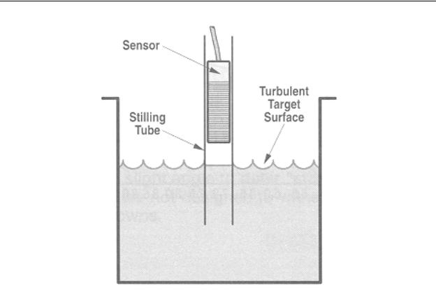
Figure 8-17 - Ultrasonic Liquid Level Sensor
(Pepperl & Fuchs, Inc.)
8-6. Optical Proximity Sensors
Optical sensors are an extremely popular method of providing discrete-output sensing of objects. Since the sensing method uses light, it is capable of sensing any objects that are opaque, regardless of the color or reflectivity of the surface. They operate over long distances (as opposed to inductive or capacitive proximity sensors), will sense in a vacuum (as opposed to ultrasonic sensors), and can sense any type of material no matter whether it is metallic, conductive, or porous. Since the optical transmitters and receivers use focused beams (using lenses), they can be operated in close proximity of other optical sensors without crosstalk or interference.
There are fundamentally three types of optical sensors. These are the thru-beam, diffuse reflective, and retro-reflective. All three types have discrete outputs. These are generally available in one of three types of light source - incandescent light, red LED and
8-16
Chapter 8 - Discrete Position Sensors
infrared LED. The red LED and IR LED types of sensors generally have a light output that is pulsed at a high frequency, and a receiver that is tuned to the frequency of the source. By doing so, these types have a high degree of immunity to other potentially interfering light sources. Therefore, red LED and IR LED sensor types function better in areas where there is a high level of ambient light (such as sunlight), or light noise (such as welding). In addition to specifying the sensor type and light source type, the designer also needs to specify whether the sensor output will be on when no light is received, or off when no light is received. Generally, this is specified as the logical condition when there is no light received, i.e., the dark condition. For this reason, the choices are specified as dark-on and dark-off.
Thru-Beam (Interrupted)
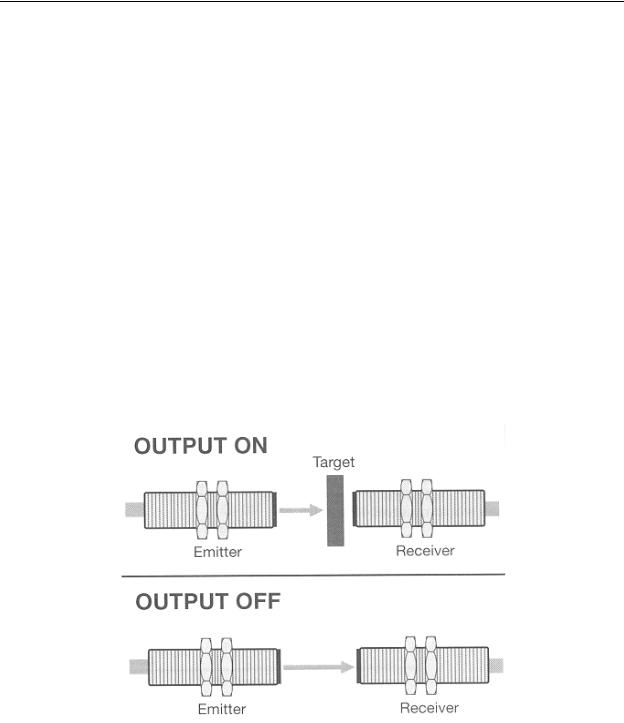
The thru-beam optical sensor consists of two separate units, each mounted on opposite sides of the object to be sensed. As shown in Figure 8-18, one unit, the emitter is the light source that provides a lens-focused beam of light that is aimed at the receiver.
The other unit, the receiver, also contains a focusing lens, and is aimed at the light source.
Assuming this is a dark-on sensor, when there is nothing blocking the light beam, the light from the source is detected by the receiver and there is no output from the receiver. However, if an object passes between the emitter and receiver, the light beam is blocked and the receiver switches on its output.
Figure 8-18 - Thru-Beam Optical Sensor, Dark On
(Pepperl & Fuchs, Inc.)
8-17
Chapter 8 - Discrete Position Sensors
Thru-beam sensors are the most commonly known to the general public since they appear in action movies in which thieves are attempting to thwart a matrix of optical burglar alarm sensors setup around a valuable museum piece.
Thru-beam opto sensors work well as long as the object to be sensed is not transparent. They have an excellent (long) maximum operating range. The main disadvantage with this type of sensor is that since the emitter and receiver are separate units, this type of sensor system requires wiring on both sides of the transport system (generally a conveyor) that is moving the object. In some cases this may be either inconvenient or impossible. When this occurs, another type of optical sensor should be considered.
Diffuse Reflective (Proximity)
The diffuse reflective optical sensor shown in, Figure 8-19, has the light emitter and receiver located in the same unit. Assuming a dark-off sensor, light from the emitter is reflected from the target object being sensed and returned to the receiver which, in turn, switches on its output. When a target object is not present, no light is reflected to the receiver and the sensor output switches off (dark-off).
Figure 8-19 - Diffuse Reflective Optical Sensor,
Dark Off (Pepperl & Fuchs, Inc.)
Diffuse reflective optical sensors are more convenient than thru-beam sensors because the emitter and receiver are located in the same housing, which simplifies wiring.
8-18
Chapter 8 - Discrete Position Sensors
However, this type of sensor does not work well with transparent targets or targets that have a low reflectivity (dull finish, black surface, etc.). Care must also be taken with glossy target objects that have multifaceted surfaces (e.g., automobile wheel covers, corrugated roofing material), or objects that have gaps through which light can pass (e.g. toy cars with windows, compact disks). These types of target objects can cause optical sensors to output multiple pulses for each object.
.
Retro-reflective (Reflex)
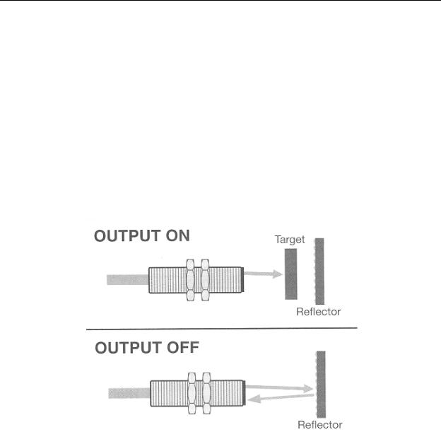
The retro-reflective optical sensors is the most sophisticated of all of the sensors. Like the diffuse reflective sensor, this type has both the emitter and receiver housed in one unit. As shown in Figure 8-20, the sensor works similarly to the thru beam sensor in that a target object passing in front of the sensor blocks the light being received. However, in this case, the light being blocked is light that is returning from a reflector. Therefore, this sensor does not require the additional wiring for the remotely located receiver unit.
Figure 8-20 - Retro-Reflective Optical Sensor,
Dark On (Pepperl & Fuchs, Inc.)
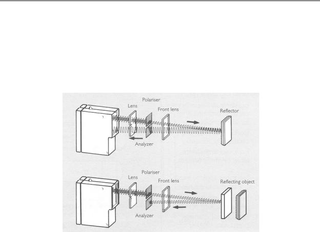
Generally, this type of sensor would not work well with glossy target objects because they would reflect light back to the receiver just as the remote reflector would. However, this problem is avoided using polarizing filters. This polarizing filter scheme is illustrated in Figure 8-21. Notice in our illustration that there is an added polarizing filter that polarizes the exiting light beam. In our illustration, this is a horizontal polarization. In the upper figure, notice that with no target object present, the specially designed reflector twists the polarization angle by 90 degrees, sending the light back in vertical polarization. At the
8-19
Chapter 8 - Discrete Position Sensors
receiver, there is another polarizing filter; however, this filter is installed with a vertical polarization to allow the light returning from the reflector to pass through and be detected by the receiver.
In the lower illustration of Figure 8-21, notice that when a target object passes between the sensor and the reflector, not only is the light beam disrupted, but if the object has a glossy surface and reflects the light beam, the reflected beam returns with the same horizontal polarization as the emitted beam. Since the receiver filter has a vertical polarization, the receiver does not receive the light, so it activates its output.
Figure 8-21 - Retro-Reflective Optical Sensor Using
Polarizing Filters (Sick Optic-Electronic, Inc.)
Retro-reflective sensors work well with all types of target objects. However, when purchasing the sensor, it is important to also purchase the reflector specified by the manufacturer. These sensors have a maximum range that is more than the diffuse reflective sensor, but less then the thru-beam sensor.
8-20

Chapter 8 - Discrete Position Sensors
Chapter 8 Review Question and Problems
1.What is the difference between a discrete sensor and an analog sensor?
2.Manufacturers specify the range of inductive proximity sensors based on what type of target metal?
3.An inductive proximity sensor has a specified range of 5mm. What is it’s range when sensing a brass target object?
4.Capacitive proximity sensors will sense metal objects as well a inductive proximity sensors. So why use inductive proximity sensors?
5.Why are ultrasonic proximity sensors not used to sense close-range objects?
6.When the beam of a thru-beam NPN dark-on optical sensor is interrupted by a target object, it’s output will be logically _____ (high or low).
7.State one disadvantage in using a thru-beam optical sensor.
8.What is the difference between a diffuse-reflective and retro-reflective optical sensor?
9.Why do retro-reflective optical sensors use polarizing light filters?
8-21