


Chapter 12 - System Integrity and Safety
12-6. Safety Interlocks
When designing control systems for heavy machinery, robotics, or high voltage systems, it is imperative that personnel are prevented from coming in contact with the equipment while it is energized. However, since maintenance personnel must have access to the equipment from time to time, it is necessary to have doors, gates, and access panels to the equipment. Therefore, it is a requirement for control systems to monitor the access points to assure that they are not opened when the equipment is energized, or conversely, that the equipment cannot be energized while the access points are opened. This monitoring method is done with interlocks.
Interlock Switches
The simplest type of interlock uses a limit switch. For example, consider the door on a microwave oven. While the door is opened, the oven will not operate. Also, if the door is opened while the oven is operating, it will automatically switch off. The reason for this is that a limit switch is positioned inside on the door latch such that when the door is unlatched, the switch is opened, and power is removed from the control circuitry. The most common drawback to switch interlocks is that they are easy to defeat. Generally, a match stick, screwdriver, or any other foreign object can be jammed into the switch mechanism to force the machine to operate. Designers go to great lengths to design interlock mechanisms that cannot be defeated.
More sophisticated interlock system can be used in lieu of limit switches. These include proximity sensors, keylocks, optical sensors, magnetically operated switches, and various combinations of these. For example, consider the interlock shown in Figure 12-6.
This is a combination deadbolt and interlock switch. When the deadbolt is closed as shown on the left, a plunger and springs activate a switch which enables the machine to be operated. When the deadbolt is opened as shown on the right, the switch opens also.
12-10

Chapter 12 - System Integrity and Safety
Figure 12-6 - Deadbolt Interlock Switch
(Scientific Technologies, Inc.)
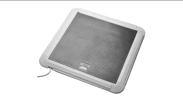
Pressure Sensitive Mat Switch
The pressure sensitive mat switch is simply a mat that will close an electrical connection when force is applied to the mat. This is illustrated in Figure 12-7. They are available in many sizes, and can be used for a wide variety of safety applications. For example, within a fenced area in which a robot operates, a mat such as this will sense when someone has stepped within the reach of the robot arm, and can disable the robot.
Another application is to place a mat in front of the operator panel of a machine. Then connect the mat such that if the contacts in the mat are not closed, the machine will not run. Keep in mind that if they are used in “deadman’s switch” applications such as this, that they can be defeated by simply sitting a heavy object on the mat.
12-11
Chapter 12 - System Integrity and Safety
Figure 12-7 - Pressure Sensitive Mat Switch
(Scientific Technologies, Inc.)
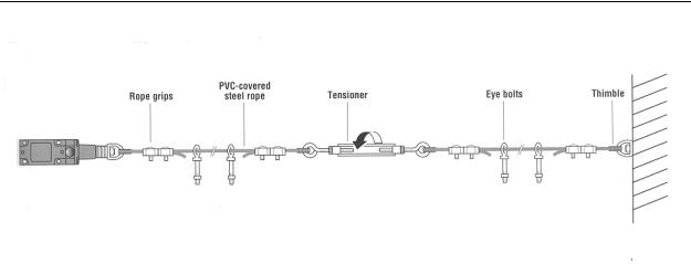
Pull Ropes
City transit buses use pull ropes on each side of the bus so that a rider can pull the rope, which switches on a buzzer notifying the driver that they wish to get off at the next stop. The technique is popular because only one switch is needed per pull rope and the rope can be of most any desired length putting it within reach over a large area. In short, it is a simple, reliable, and inexpensive mechanism. This same idea can be applied to machine controls as an emergency shutoff method. Figure 12-8 shows a pull rope interlock. The rope is securely fastened to a fixed thimble on one end and to a pull switch on the other. A turnbuckle tensioner allows for the slack to be adjusted out of the rope, and eye bolts support the rope. If necessary, the rope can even be routed round corners using pulleys. In use, the switch is N/C and connected into the controls as an additional STOP switch. When the rope is pulled by anyone, the switch contacts open and the machine stops.
12-12
Chapter 12 - System Integrity and Safety
Figure 12-8 - Pull Rope Interlock Switch
(Scientific Technologies, Inc.)
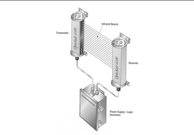
Light Curtains
When it is imperative that an operator’s hands stay out of certain areas of a machine while it is operating, one excellent way to assure this is by using a light curtain. It is basically a “spinoff” of the thru-beam optical sensor; however, instead of the beam being a single straight line, the beam is extended (by scanning) to cover a plane, and the receiver senses the scanning beam over the entire plane. Any object intersecting the light curtain plane causes the electronic circuitry in the light curtain to output a discrete signal which can be used by the control circuitry to shut down the machine. The light used in this system is infrared and pulsed. Since it is infrared, it is invisible and does not distract the machine operator. Since the light is pulsed, it is relatively immune to flourescent lights, arc welding, sunlight, and other light interference.
As shown in Figure 12-9, light curtains generally come in three parts - the transmitter wand, the receiver wand, and the power supply & logic (electronic) enclosure. The transmitter and receiver wands strictly produce and detect the infrared beams that makeup the plane of detection. They are connected by electrical cables to the electronic enclosure, which contains all the necessary circuitry to operate the wands, power the system, make logical decisions based on the interrupted beams, and provide relay outputs. This is a complete “turnkey” stand-alone system. The designer simply supplies AC line power, and connects the relay outputs to the machine controls.
12-13
Chapter 12 - System Integrity and Safety
Figure 12-9 - Light Curtain Components
(Scientific Technologies, Inc.)
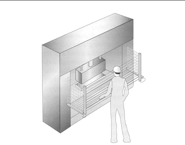
If interlock coverage is needed over several planes, the transmitter and receiver wands of the light curtain can be cascaded as shown in Figure 12-10. In this case, two wands are cascaded on each end of the work area. One pair are transmitter wands and the other pair are receiver wands. One pair of vertically positioned wands provides a vertical light curtain directly in front of the operator, and a second pair of horizontally positioned wands provides a horizontal light curtain underneath the work area. By doing this the designer can realize some cost savings, since all the wands can be operated by one electronics enclosure.
12-14
Chapter 12 - System Integrity and Safety
Figure 12-10 - Cascaded Light Curtains
(Scientific Technologies, Inc.)
12-15
Chapter 12 - System Integrity and Safety
Chapter 12 Review Question and Problems
1.Select the best NEMA number for an electrical box mounted on an above ground swimming pool pump. It will be exposed to outdoor weather and an occasional splash of chlorinated (corrosive) pool water.
2.Select the best IEC IP number for an electrical box used in a textile mill. It must be dust tight and be able to withstand an occasional water hosedown by the cleaning crew.
3.Convert the IEC rating IP64 to the nearest equivalent NEMA rating.
12-16