


Chapter 12 - System Integrity and Safety
12-4. Equipment Temperature Considerations
It is a proven fact that the length of life of an electronic device is inversely proportional to the temperature at which it is operated. In other words, to make electronic equipment last longer, it should be operated in a low temperature environment. Obviously, it is impractical to refrigerate controls installations. However, it is important to take necessary steps to assure that the equipment does not overheat, nor exceed manufacturer’s specifications of maximum allowable operating temperature.
When electrical equipment is installed inside a NEMA or IEC enclosure, it will most certainly produce heat when powered which will raise the temperature inside the enclosure. It is important that this heat be somehow dissipated. Since most cabinets used in an often dirty manufacturing environment are sealed (to keep out dirt and dust), the most popular way to do this is to use the cabinet itself as a heat sink. Generally, the cabinet is made of steel and is bolted to a beam or to the metal side of the machine, which improves the heat sinking capability of the enclosure. If this type of enclosure mounting is not available, the temperature of the inside of the enclosure should be measured under worst case conditions; that is with all equipment in the enclosure operating under worst case load conditions.
Another way of controlling temperature inside and enclosure is by using a cooling fan. However, this will require screens and filters to cleanse the air being drawn into the cabinet. This, in turn, increases periodic maintenance to clean the screens and filters.
12-5. Fail Safe Wiring and Programming
In most examples in the earlier chapters of this text, we used all normally open momentary pushbutton switches connected to PLCs. However, what would happen if we used a normally open pushbutton switch for a stop switch, and one of the wires on the switch became loose or broken, as shown in Figure 12-1? Naturally, when we press the stop switch, the PLC will not receive a signal input, and the machine will simply continue running.
12-5
Chapter 12 - System Integrity and Safety
START |
PLC |
|
|
|
|
RUN |
CR1 |
||
|
|
|
||
|
IN1 |
OUT1 |
|
|
PB1 |
|
|
||
|
|
|
|
|
STOP |
|
|
|
|
PB2 |
IN2 |
OUT2 |
|
|
|
|
|
|
|
Broken Wire |
IN3 |
OUT3 |
|
|
|
|
|
||
|
IN4 |
OUT4 |
|
|
120V |
|
|
120V |
|
CONTROL |
|
|
CONTROL |
|
VOLTAGE |
|
|
VOLTAGE |
|
|
COM |
COM |
|
|
Figure 12-1 - Non-Failsafe Wiring of
STOP Switch
The problem is that a design of this type is not failsafe. Failsafe design is a method of designing control systems such that if a critical component in the system fails, the system immediately becomes disabled.
Let us reconsider our stop switch example, except this time, we will have the STOP switch provide a signal to the PLC when we DO NOT want to it to stop. In other words, we will use a normally closed (N/C) pushbutton switch that, when pressed, will break the circuit. This change will also require that we invert the STOP switch signal in the PLC ladder program. Then if one of the wires on the STOP switch breaks as shown in Figure 12-2, the PLC no longer “sees” an input from the STOP switch. The PLC will interpret this as if someone has pressed the switch, and it will stop the machine. In addition, as long as the PLC program is written such that the STOP overrides the START, then if the wire on the STOP switch breaks, not only will the machine stop, but pressing the START switch will have no effect either.
12-6
Chapter 12 - System Integrity and Safety
START |
PLC |
|
|
|
|
RUN |
CR1 |
||
|
|
|
||
|
IN1 |
OUT1 |
|
|
PB1 |
|
|
||
|
|
|
|
|
STOP |
|
|
|
|
PB2 |
IN2 |
OUT2 |
|
|
|
|
|
|
|
Broken Wire |
IN3 |
OUT3 |
|
|
|
|
|
||
|
IN4 |
OUT4 |
|
|
120V |
|
|
120V |
|
CONTROL |
|
|
CONTROL |
|
VOLTAGE |
|
|
VOLTAGE |
|
|
COM |
COM |
|
|
Figure 12-2 - Failsafe Wiring of STOP Switch
Failsafe wiring applies to PLC outputs also. Consider an application where a PLC is to control a crane. Naturally there will be a disk braking system that will lock the wench and prevent a load on the crane from being lowered. In order to be failsafe, this braking system needs to be on when electrical power is off. In other words, it needs to be held on by mechanical spring pressure and released by electrical, hydraulic, pneumatic, or any other method. In doing so, any failure of the powering system will cause the breaking system to loose power and the spring will automatically apply the brake. This means that it requires a relay contact closure from the PLC output to release the brake, instead of applying the brake.
Since emergency stop switches are critical system components, it is important that these always operate correctly and that they are not buffered by some other electronic system. Emergency stop switches are always connected in series with the power line of the control system and, when pressed, will interrupt power to the controls. When this happens, failsafe output design will handle the disabling and halting of the system.
Since PLC ladder programming is simply an extension of hard wiring, it is important to consider failsafe wiring when programming also. Consider the start/stop program rung shown in Figure 12-3. This rung will appear to work normally; that is, when the START is momentarily pressed, relay RUN switches on and remains on. When STOP is pressed, RUN switches off. However, consider what happens when both START and STOP are
12-7

Chapter 12 - System Integrity and Safety
pressed simultaneously. For this program, START will override STOP and RUN will switch on as long as START is pressed.
| |
START |
|
RUN |
1--- |
| |------------------------------------------------------------------- |
|
(OUT)| |
| |
RUN |
STOP |
| |
|--- |
| |------- |
|/|--- |
+ |
| |
|
|
|
|
|
|
Figure 12-3 - Unsafe Start/Stop Program |
Now consider an improved version of this program shown in Figure 12-4. Notice that by moving the STOP contact into the main part of the rung, the START switch can no longer override the STOP. This program is considered safer than the one in Figure 12-3.
| |
START |
STOP |
RUN |
1--- |
| |------- |
|/|--------------------------------------------------------- |
(OUT)| |
| |
RUN |
| |
|
|--- |
| |--- |
+ |
|
| |
|
|
|
| |
|
|
|
Figure 12-4 - Improved Start/Stop Program With Overriding STOP
Generally, PLCs are extremely reliable devices. Most PLC failures can be attributed to application errors (overvoltage on inputs, overcurrents on outputs), or extremely harsh environmental conditions, such as over-temperature or lightening strike, to name a few.
However, there are some applications where even more reliability is desired. These include applications where a PLC failure could result in injury or loss of life. For these applications, the designer must be especially careful to consider what will happen if power fails, and what will happen if the PLC should fail with one or more outputs stuck ON or stuck OFF.
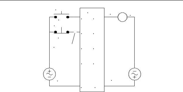
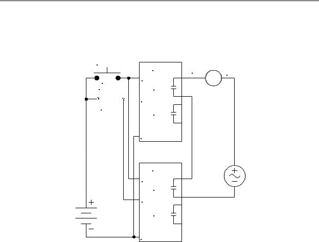
Having a power failure on a PLC system is a situation that can be handled by failsafe design. However, the situation in which a PLC fails to operate correctly can be catastrophic, and no amount of failsafe design using a single PLC can prevent this. This situation can be best handled by using redundant PLC design. In this case, two identical PLCs are used that are running identical programs. The inputs of the PLCs are wired in parallel, and the outputs of the PLC are wired in series (naturally, to do this the outputs must be of the mechanical relay type)
Consider the redundant PLC system shown in Figure 12-5. For this system, the program is written so that when PB1 is pressed, IN1 on both PLC1 and PLC2 is energized. Since both PLCs are running the same program, they will both switch on their OUT1 relay.
Since PLC1 OUT1 and PLC2 OUT1 are connected in series, when they both switch on, relay CR1 will be energized. However, assume that the PLC1 OUT1 relay becomes stuck ON because of either a relay failure or a PLC1 firmware crash. In this case, assuming
12-8
Chapter 12 - System Integrity and Safety
PLC2 is still operating normally, its OUT1 will also continue to operate normally switching
CR1 on and off properly. Conversely, if PLC1 OUT1 fails in the stuck OFF position, then CR1 will not operate and the machine will fail to run. In either case failure of one PLC does not create an unsafe condition.
START
|
PLC1 |
RUN |
CR1 |
|
|
||
|
IN1 |
|
|
PB1 |
|
|
|
STOP |
OUT1 |
|
|
 IN2
IN2
PB2
OUT2
COM
PLC2
IN1
OUT1
IN2
OUT2
COM
Figure 12-5 - Increasing Reliability by Redundant PLC Design
One drawback to the redundant system shown in Figure 12-5 is that if one of the relays fails in the stuck ON condition, the system will continue to function normally. Although this is not hazardous, it defeats the purpose of having two PLCs in the system, which is to increase the reliability and safety. It would be helpful to have the PLC’s identify when this occurs and give some indication of a PLC fault condition. This is commonly done by a method called output readback. In this case, the inputs and outputs must be of the same voltage type (e.g. 120VAC), and additional inputs are purchased for the PLCs so that outputs can be wired back to unused inputs. Then additional code is added to the programs to compare the external readback signal to the internal signal that produced the output. This is done using the disagreement (XOR) circuit. Any disagreement is cause for a fault condition.
12-9