


Chapter 2 - The Programmable Logic Controller
Chapter 2 - The Programmable Logic Controller
2-1. Objectives
Upon completion of this chapter you will know
”the history of the programmable logic controller.
”why the first PLCs were developed and why they were better than the existing control methods.
”the difference between the open frame, shoebox, and modular PLC configurations, and the advantages and disadvantages of each.
”the components that make up a typical PLC.
”how programs are stored in a PLC.
”the equipment used to program a PLC.
”the way that a PLC inputs data, outputs data, and executes its program.
”the purpose of the PLC update.
”the order in which a PLC executes a ladder program.
”how to calculate the scan rate of a PLC.
2-2. Introduction
This chapter will introduce the programmable logic controller (PLC) with a brief discussion of it's history and development, and a study of how the PLC executes a program. A physical description of the various configurations of programmable logic controllers, the functions associated with the different components, will follow. The chapter will end with a discussion of the unique way that a programmable logic controller obtains input data, process it, and produces output data, including a short introduction to ladder logic.
It should be noted that in usage, a programmable logic controller is generally referred to as a “PLC” or “programmable controller”. Although the term “programmable controller” is generally accepted, it is not abbreviated “PC” because the abbreviation “PC” is usually used in reference to a personal computer. As we will see in this chapter, a PLC is by no means a personal computer.
2-1

Chapter 2 - The Programmable Logic Controller
2-3. A Brief History
Early machines were controlled by mechanical means using cams, gears, levers and other basic mechanical devices. As the complexity grew, so did the need for a more sophisticated control system. This system contained wired relay and switch control elements. These elements were wired as required to provide the control logic necessary for the particular type of machine operation. This was acceptable for a machine that never needed to be changed or modified, but as manufacturing techniques improved and plant changeover to new products became more desirable and necessary, a more versatile means of controlling this equipment had to be developed. Hardwired relay and switch logic was cumbersome and time consuming to modify. Wiring had to be removed and replaced to provide for the new control scheme required. This modification was difficult and time consuming to design and install and any small "bug" in the design could be a major problem to correct since that also required rewiring of the system. A new means to modify control circuitry was needed. The development and testing ground for this new means was the U.S. auto industry. The time period was the late 1960's and early 1970's and the result was the programmable logic controller, or PLC. Automotive plants were confronted with a change in manufacturing techniques every time a model changed and, in some cases, for changes on the same model if improvements had to be made during the model year. The PLC provided an easy way to reprogram the wiring rather than actually rewiring the control system.
The PLC that was developed during this time was not very easy to program. The language was cumbersome to write and required highly trained programmers. These early devices were merely relay replacements and could do very little else. The PLC has at first gradually, and in recent years rapidly developed into a sophisticated and highly versatile control system component. Units today are capable of performing complex math functions including numerical integration and differentiation and operate at the fast microprocessor speeds now available. Older PLCs were capable of only handling discrete inputs and outputs (that is, on-off type signals), while today's systems can accept and generate analog voltages and currents as well as a wide range of voltage levels and pulsed signals. PLCs are also designed to be rugged. Unlike their personal computer cousin, they can typically withstand vibration, shock, elevated temperatures, and electrical noise to which manufacturing equipment is exposed.
As more manufacturers become involved in PLC production and development, and
PLC capabilities expand, the programming language is also expanding. This is necessary to allow the programming of these advanced capabilities. Also, manufacturers tend to develop their own versions of ladder logic language (the language used to program PLCs).
This complicates learning to program PLC's in general since one language cannot be learned that is applicable to all types. However, as with other computer languages, once the basics of PLC operation and programming in ladder logic are learned, adapting to the various manufacturers’ devices is not a complicated process. Most system designers
2-2

Chapter 2 - The Programmable Logic Controller
eventually settle on one particular manufacturer that produces a PLC that is personally comfortable to program and has the capabilities suited to his or her area of applications.
2-4. PLC Configurations
Programmable controllers (the shortened name used for programmable logic controllers) are much like personal computers in that the user can be overwhelmed by the vast array of options and configurations available. Also, like personal computers, the best teacher of which one to select is experience. As one gains experience with the various options and configurations available, it becomes less confusing to be able to select the unit that will best perform in a particular application.
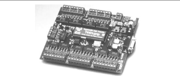
Basic PLCs are available on a single printed circuit board as shown in Figure 2-1. They are sometimes called single board PLCs or open frame PLCs. These are totally self contained (with the exception of a power supply) and, when installed in a system, they are simply mounted inside a controls cabinet on threaded standoffs. Screw terminals on the printed circuit board allow for the connection of the input, output, and power supply wires. These units are generally not expandable, meaning that extra inputs, outputs, and memory cannot be added to the basic unit. However, some of the more sophisticated models can be linked by cable to expansion boards that can provide extra I/O. Therefore, with few exceptions, when using this type of PLC, the system designer must take care to specify a unit that has enough inputs, outputs, and programming capability to handle both the present need of the system and any future modifications that may be required. Single board PLCs are very inexpensive (some less than $100), easy to program, small, and consume little power, but, generally speaking, they do not have a large number of inputs and outputs, and have a somewhat limited instruction set. They are best suited to small, relatively simple control applications.
2-3
Chapter 2 - The Programmable Logic Controller
Figure 2-1 - Open Frame PLC
(Triangle Research Inc., Pte. Ltd.)
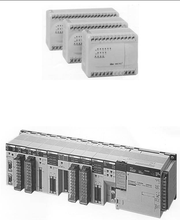
PLCs are also available housed in a single case (sometimes referred to as a shoe box) with all input and output, power and control connection points located on the single unit, as shown in Figure 2-2. These are generally chosen according to available program memory and required number and voltage of inputs and outputs to suit the application.
These systems generally have an expansion port (an interconnection socket) which will allow the addition of specialized units such as high speed counters and analog input and output units or additional discrete inputs or outputs. These expansion units are either plugged directly into the main case or connected to it with ribbon cable or other suitable cable.
2-4
Chapter 2 - The Programmable Logic Controller
Figure 2-2 - Shoebox-Style PLCs
(IDEC Corp.)
More sophisticated units, with a wider array of options, are modularized. An example of a modularized PLC is shown in Figure 2-3.
Figure 2-3 - Modularized PLC
(Omron Electronics)
2-5

Chapter 2 - The Programmable Logic Controller
The typical system components for a modularized PLC are:
1. Processor.
The processor (sometimes call a CPU), as in the self contained units, is generally specified according to memory required for the program to be implemented. In the modularized versions, capability can also be a factor. This includes features such as higher math functions, PID control loops and optional programming commands. The processor consists of the microprocessor, system memory, serial communication ports for printer, PLC LAN link and external programming device and, in some cases, the system power supply to power the processor and I/O modules.
2. Mounting rack.
This is usually a metal framework with a printed circuit board backplane which provides means for mounting the PLC input/output (I/O) modules and processor. Mounting racks are specified according to the number of modules required to implement the system. The mounting rack provides data and power connections to the processor and modules via the backplane. For CPUs that do not contain a power supply, the rack also holds the modular power supply. There are systems in which the processor is mounted separately and connected by cable to the rack. The mounting rack can be available to mount directly to a panel or can be installed in a standard
19" wide equipment cabinet. Mounting racks are cascadable so several may be interconnected to allow a system to accommodate a large number of I/O modules.
3. Input and output modules.
Input and output (I/O) modules are specified according to the input and output signals associated with the particular application. These modules fall into the categories of discrete, analog, high speed counter or register types.
Discrete I/O modules are generally capable of handling 8 or 16 and, in some cases 32, on-off type inputs or outputs per module. Modules are specified as input or output but generally not both although some manufacturers now offer modules that can be configured with both input and
2-6
Chapter 2 - The Programmable Logic Controller
output points in the same unit. The module can be specified as AC only, DC only or AC/DC along with the voltage values for which it is designed.
Analog input and output modules are available and are specified according to the desired resolution and voltage or current range. As with discrete modules, these are generally input or output; however some manufacturers provide analog input and output in the same module. Analog modules are also available which can directly accept thermocouple inputs for temperature measurement and monitoring by the PLC.
Pulsed inputs to the PLC can be accepted using a high speed counter module. This module can be capable of measuring the frequency of an input signal from a tachometer or other frequency generating device. These modules can also count the incoming pulses if desired. Generally, both frequency and count are available from the same module at the same time if both are required in the application.
Register input and output modules transfer 8 or 16 bit words of information to and from the PLC. These words are generally numbers (BCD or Binary) which are generated from thumbwheel switches or encoder systems for input or data to be output to a display device by the PLC.
Other types of modules may be available depending upon the manufacturer of the PLC and it's capabilities. These include specialized communication modules to allow for the transfer of information from one controller to another. One new development is an I/O Module which allows the serial transfer of information to remote I/O units that can be as far as
12,000 feet away.
4. Power supply.
The power supply specified depends upon the manufacturer's PLC being utilized in the application. As stated above, in some cases a power supply capable of delivering all required power for the system is furnished as part of the processor module. If the power supply is a separate module, it must be capable of delivering a current greater than the sum of all the currents needed by the other modules. For systems with the power supply inside the CPU module, there may be some modules in the system which require excessive power not available from the processor either because of voltage or current requirements that can only be achieved through the addition of a second power source. This is generally true if analog or
2-7

Chapter 2 - The Programmable Logic Controller
external communication modules are present since these require ± DC supplies which, in the case of analog modules, must be well regulated.
5. Programming unit.
The programming unit allows the engineer or technician to enter and edit the program to be executed. In it's simplest form it can be a hand held device with a keypad for program entry and a display device (LED or LCD) for viewing program steps or functions, as shown in Figure 2-4. More advanced systems employ a separate personal computer which allows the programmer to write, view, edit and download the program to the PLC. This is accomplished with proprietary software available from the PLC manufacturer. This software also allows the programmer or engineer to monitor the PLC as it is running the program. With this monitoring system, such things as internal coils, registers, timers and other items not visible externally can be monitored to determine proper operation. Also, internal register data can be altered if required to fine tune program operation. This can be advantageous when debugging the program. Communication with the programmable controller with this system is via a cable connected to a special programming port on the controller. Connection to the personal computer can be through a serial port or from a dedicated card installed in the computer.
2-8