

Chapter 9 - Encoders, Transducers, and Advanced Sensors
Solution:
First, find the resolution of a 10-bit encoder, which is 360 degrees / 210 = 0.35156 degree. Then convert 0011100101G to binary using the method described previously. This will result in the binary number 0010111001. Now convert this number to its decimal equivalent, which is 185, and multiply it by the resolution to get 185 x 0.35156 = 65.04 degrees.
9-11. Linear Displacement
Potentiometer
A slide potentiometer is the simplest of all linear displacement sensors. It’s principle of operation is simply that we apply a voltage to a resistor and then move a slider across the resistor. The voltage appearing on the slider is proportional to the physical position of the slider on the resistor. Generally, in most displacement sensing linear resistors, the resistive element is made from small wire. This makes the unit more durable and less sensitive to variations in temperature and humidity. These are called slidewire potentiometers. The most common applications for slidewire potentiometers are in XY plotters and chart recorders.
Linear Variable Differential Transformer (LVDT)
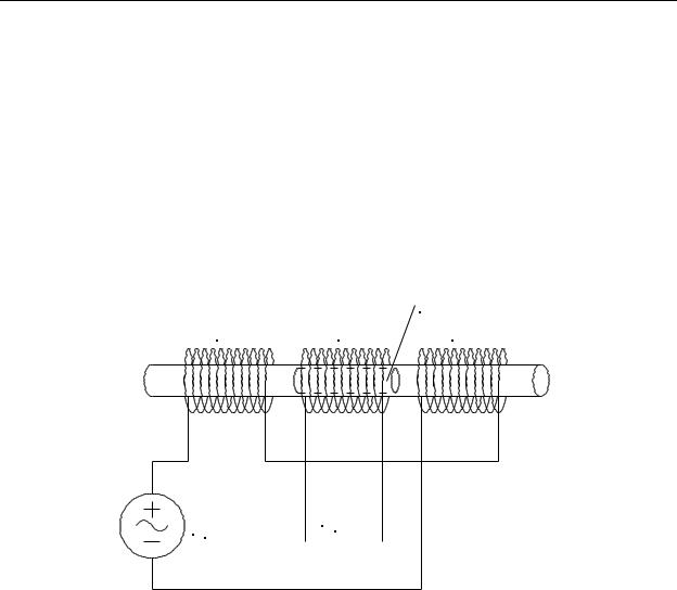
The linear variable differential transformer, or LVDT, is an old technology that is still very popular. The device operates on the principle that the amount of coupling between the primary and secondary of a transformer depends on the placement of the transformer core material. Consider the LVDT shown in Figure 9-33. Identical coils (equal numbers of turns and equal size wire) L1 and L2 make up the primary of the transformer, with L3 being the secondary. All three coils are wound on a non-metallic tube. L1 and L2 are connected such that the same alternating current passes through both coils, but in opposite directions. This means that the magnetic fields produced by L1 and L2 will be equal but opposite. At the exact center between L1 and L2, the magnetic fields from the two coils will cancel producing a net field of zero. Therefore, the induced voltage in coil L3 will also be zero.
A high permeability iron slug is positioned inside the tube and a rod from the slug connects to the moving mechanical part to be sensed. As long as the slug remains centered, the flux coupled from coils L1 and L2 into L3 will be equal and opposite and will produce no induced voltage in L3. However, if the slug is moved slightly to the right, the permeability of the slug will lower the reluctance for coil L2 and increase the magnetic flux
9-37
Chapter 9 - Encoders, Transducers, and Advanced Sensors
coupled from L2 to L3. At the same time, less flux from L1 will be coupled to L3. This will cause a small voltage to be induced in L3 that is in-phase with the voltage applied to L2. Moving the slug farther to the right will cause a proportional increase in the amplitude of the voltage induced in L3.
If we move the slug to the left of center, more of the magnetic flux from L1 will be coupled to L3 causing an induced voltage that is in-phase with the voltage applied to L1. Notice that since L1 and L3 are connected in opposite polarity, moving the slug to the left will cause a phase reversal in the voltage induced in L3 as compared to moving the slug to the right. Therefore, by measuring the amplitude of the induced voltage in L3, we can determine the magnitude of the displacement of the slug from the center, and by measuring the phase relationship between the induced voltage in L3 and the applied voltage Vin, we can determine whether the direction of displacement is right or left.
|
|
Movable Iron Slug |
L1 |
L3 |
L2 |
Vin Vout
Figure 9-33 - Linear Variable Differential Transformer
(LVDT)
Naturally, both the AC amplitude and phase of the voltage Vout must conditioned in order to provide a DC output voltage that is proportional to the displacement of the iron slug. Because of this, modern LVDTs come with built-in signal conditioning electronic circuitry. They are generally powered by dual 15 volt power supplies and produce an output voltage of either -5 to +5 volts or -10 to +10 volts over the range of mechanical travel.
9-38

Chapter 9 - Encoders, Transducers, and Advanced Sensors
Ultrasonic
The ultrasonic distance sensor works in the same manner as the ultrasonic proximity sensor. However, instead of a discrete output, the sensor has an analog output that is proportional to the distance from the sensor to the target object. The ultrasonic distance sensor has the same advantages and disadvantages as the ultrasonic proximity sensor.
Glass Scale Encoders
If we were to unwrap the glass disk of a rotary encoder and make it a straight narrow glass scale, we could easily have an encoder that would, instead of producing angular position information, produce linear displacement information. Like rotary encoders, glass scale encoders are available in both incremental and absolute versions. Their principles of operation are identical to that of their rotary counterparts. Since they are capable of detecting linear movements as small as 0.0001" or less, they are commonly used in applications that require extreme accuracy and repeatability such as numerically controlled mill and lathe machines.
Magnetostrictive Sensors
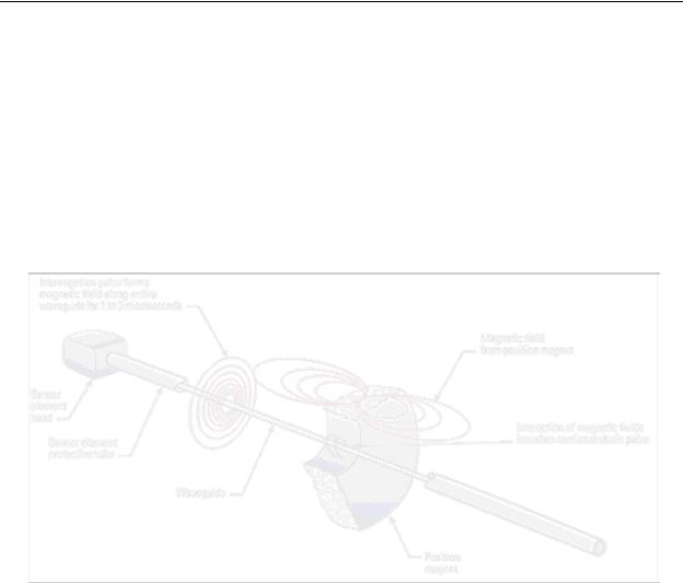
The magnetostrictive linear displacement sensor is a relatively new technology that has been perfected for making precise measurements of linear motion and position. The system utilizes two fundamental physical properties: a) whenever a current is passed through a conductor resting in a magnetic field, there will be a mechanical force produced, and b) sound waves travel through a solid material at a predictable velocity.
Consider the cutaway drawing of a magnetostrictive position sensor shown in Figure 9-34. The sensor unit consists of a sensor element head, waveguide, and sensor element protective tube. The sensor element head contains the electronic circuitry to operate the system. The waveguide is fundamentally a length of steel wire. For this application, it must be both conductive and elastic (much like a piano string). The sensor element tube is conductive and provides a protective shell for the waveguide. External to
(and separate from) these elements is a toroidal permanent magnet. The magnet is generally attached to the mechanism that moves, while the sensor element head, waveguide, and tube remain stationary. The waveguide tube is inserted through the hole in the toroidal magnet.
In operation, the sensor element head generates an extremely short current pulse that is applied to the waveguide. This pulse will cause a magnetic field to be induced around the waveguide. This magnetic field will interact with the stationary magnetic field produced by the toroidal magnet causing a very short mechanical pulse to be produced on
9-39
Chapter 9 - Encoders, Transducers, and Advanced Sensors
the waveguide. This is much like plucking the string of a guitar; however, in this case the mechanical force is a torsional (twisting) force. This mechanical pulse causes a torsional wave to begin traveling down the waveguide toward the sensor element head. The system works much like sonar, except that we have a transmitted electrical signal that produces a mechanical echo.
The sensor element head contains a mechanical transducer that measures torsional motion of the waveguide and converts it to an electrical pulse. Then the electronic circuitry in the sensor element head measures the elapsed time between the current pulse and the returning mechanical pulse. This time is directly proportional to the distance the permanent magnet is located from the sensor element head. The pulse delay is then converted to an analog voltage which appears on the output terminals of the sensor.
Figure 9-34 - Magnetostrictive Position Sensor, Cutaway View
(MTS Systems Corp.)
The electronic circuitry is generally calibrated to have an output range of 0 to 10 volts. Zero volts corresponds to a distance of zero (i.e., the magnet is located at the sensor head end of the tube) and 10 volts corresponds to the full length of the tube. Sensors are available with various length tubes. As an example, assume we are using a 24" sensor. In this case, 10 volts = 24", and all positions from 0" to 24" are scaled proportionally.
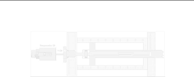
As an application example, consider the arrangement shown in Figure 9-35. This shows a cutaway view of a hydraulic cylinder on the right and a magnetostrictive sensor on the left. The shaft of the hydraulic cylinder has been bored to make room for the sensor’s waveguide tube. The toroidal permanent magnet is fastened to the face of the piston inside the cylinder. As the hydraulic cylinder extends or contracts, the magnet will
9-40
Chapter 9 - Encoders, Transducers, and Advanced Sensors
move to the right and left on the waveguide tube. This will cause the sensor to output a voltage that is proportional to the mechanical extension of the hydraulic cylinder. This method is widely used in flight simulators to precisely and smoothly control the hydraulic cylinders that move the platform.
Figure 9-35 - Magnetostrictive Sensor Measurement of
Hydraulic Cylinder Displacement
(MTS Systems Corp.)
Example Problem:
A 36" magnetostrictive sensor has a specified output voltage range of 0-10volts. If it is outputting 8.6 volts, how far is the magnet positioned from the sensor head?
Solution:
The answer can be found by using a simple ratio: 10V is to 36" as 8.6V is to X”.
Therefore, X = 30.96".
9-41

Chapter 9 - Encoders, Transducers, and Advanced Sensors
Chapter 9 Review Question and Problems
1.When a bi-metallic strip is heated, it bends in the direction of the side that has the _____ (high or low) coefficient of expansion.
2.What is the Seebeck voltage?.
3.What is chromel? What is alumel?
4.A 200 ohm platinum RTD measures 222 ohms. What is its temperature?
5.A N/O float switch closes when the liquid level is ___ (low or high).
6.A 100mm long metal rod is compressed and measures 97mm. What is the strain?
7.A 1k ohm strain gage is connected into a bridge circuit with the other three
resistors R1 = R2 = R3 = 1k ohms. The bridge is powered by a 10 volt DC power supply. The strain gage has a gage factor k = 1.5. The bridge is
balanced (Vout = 0 volts) when the strain :, = 0. What is the strain when Vout = +200 microvolts?
8.A 0 to +500psi pressure transducer has a calibration factor of 100 psi/volt. a) What is the pressure if the transducer output is 1.96 volts? b) What is the full scale output voltage of the transducer?
9.Water is flowing at 10 mph in a square concrete drainage canal that is
10' wide. The water in the canal is 5' deep. What is the flow in ft3/sec?
10.What is an advantage in using a thermal dispersion flow switch as opposed to other types of flow switches?
11.A slotted disk and opto-interrupter as shown in Figure 9-27 outputs pulses at 620 Hz. What is the rotating speed of the disk in rpms?
12.A 3600 pulse incremental encoder is outputting a 2.5 kHz square wave.
What is a) the resolution of the encoder, and b) the speed of rotation?
13.A 10-bit absolute optical encoder is outputting the octal number 137. What is its shaft position with respect to mechanical zero?
14.A 10 bit absolute optical encoder is outputting the gray code number 1000110111. What is its shaft position with respect to mechanical zero?
9-42

Chapter 9 - Encoders, Transducers, and Advanced Sensors
15.A 16 inch magnetostrictive sensor has a full scale output of 10 volts. When it is outputting 3.55 volts, how far is the magnet from the sensor element head?
9-43