

Chapter 9 - Encoders, Transducers, and Advanced Sensors
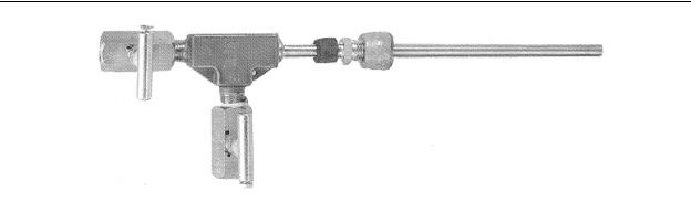
Figure 9-23 - Pitot Tube Flow Sensor
(Omega Instruments)
9-8. Inclination
Inclination sensors are generally called inclinometers or tilt gages. Inclinometers usually have an electrical output while tilt gages have a visual output (usually a meter or fluid bubble indication). Inclinometers normally have an analog output, but if they have a discrete output they are called tilt switches.
The most popular inclinometer is the electrolytic inclinometer. This device consists of a glass tube with three electrodes, one mounted in each end and one in the center. The tube is filled with a non-conductive liquid (such as glycol) which acts as the electrolyte. Since the tube is not completely filled with liquid, there will be a bubble in the tube, much like a carpenter’s bubble level. As the tube is tilted this bubble will travel away from the center line of the tube. A typical inclinometer tube is shown on the left of Figure 9-24.
Since there are electrodes in each end of the tube, there are two capacitors formed within the tube - one capacitor is from one end electrode and the center electrode, and the other capacitor is from the other end electrode and the center electrode. As long as the tube is level, the bubble is centered and each capacitor has the same amount of electrolyte between its electrode pair, thus making the two capacitor values equal. However, when the tube is tilted, the bubble shifts position inside the tube. This changes the amount of dielectric (electrolyte) between the electrodes which causes a corresponding shift in the capacitance ratio between the two capacitors. By connecting the two capacitors in the tube into an AC Wheatstone bridge and measuring the output voltage, the shift in capacitance ratio (and the amount of tilt) can be measured as a change in voltage, and the direction of tilt can be measured by analyzing the direction of phase shift.
9-24
Chapter 9 - Encoders, Transducers, and Advanced Sensors
Figure 9-24 - Inclinometer Tube (Left)
and Inclinometer Assemblies (Right)
(The Fredericks Company)
When installing the inclinometer, it is extremely important to make sure that the measurement axis of the inclinometer is aligned with the direction of the inclination to be measured. This is because inclinometers are designed to ignore tilt in any direction except the measurement axis (this is called cross-axis rejection or off-axis rejection). The inclinometer must also be mechanically zeroed after installation. This is done using adjustment screws or adjustment nuts as shown on the right of Figure 9-24.
The inclinometer system output voltage after signal conditioning and calibration is usually graduated in volts/degree or, for the more sensitive inclinometers, volts/arcminute. The signal conditioning and calibration allow the designer to connect the output of the inclinometer system directly to the analog input of a PLC.
9-9. Acceleration
Acceleration sensors (called accelerometers) are use in a variety of applications including aircraft g-force sensors, automotive air bag controls, vibration sensors, and instrumentation for many test and measurement applications. Acceleration measurement is very similar to inclination measurement with the output being graduated in volts/g instead of volts/degree. However, the glass tube electrolytic inclination method described above cannot be used because the accelerometer must be capable of accurate measurements
9-25
Chapter 9 - Encoders, Transducers, and Advanced Sensors
in any physical position. For example, if we were to orient an accelerometer so that it is standing on end, it should output an acceleration value of 1g. Glass tube inclinometers will reach a saturation point under extreme inclinations, accelerometers will not.
Acceleration measurement sounds somewhat complicated, however, it actually is relatively simple. One method to measure acceleration is to use a known mass connected to a pressure strain gage as shown previously in Figure 9-15. Instead of the diaphragm being distorted by fluid or gas pressure, it is distorted by the force from a known mass resting against the diaphragm. When a pressure strain gage is used to measure weight (or acceleration), the device is called a load cell.
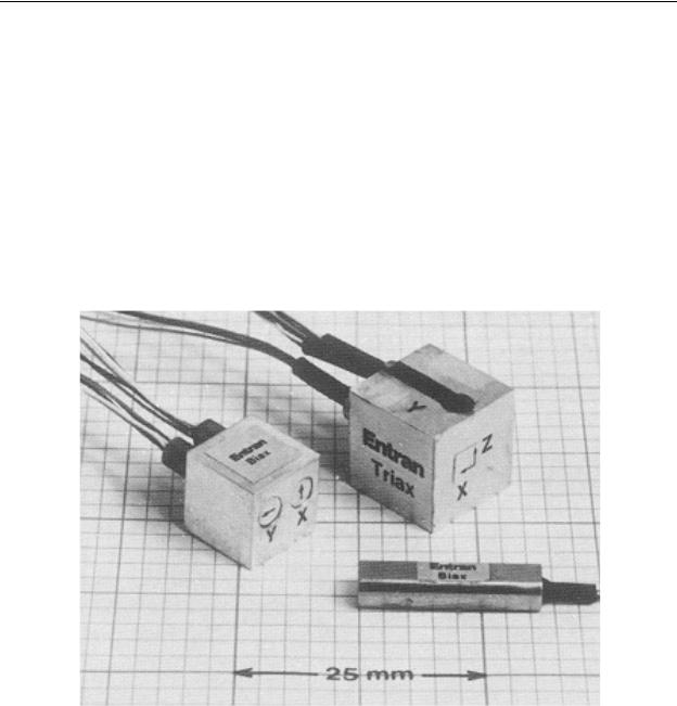
Figure 9-25 shows three strain gage accelerometers. In the lower right corner of the figure is a one axis accelerometer, on the left is a 2-axis accelerometer, and in the upper right is a 3-axis accelerometer. Note that each measurement axis is marked on the device.
Figure 9-25 - Strain Gage Accelerometers
(Entran Sensors and Electronics)
Each accelerometer requires a strain gage bridge compensation resistor and amplifier as shown in Figure 9-26. In this figure, the IMV Voltage Module is an instrumentation amplifier with voltage output. In some applications, the strain gage bridge compensation resistor and amplifier are included in the strain gage module.
9-26
Chapter 9 - Encoders, Transducers, and Advanced Sensors
Figure 9-26 - Strain Gage Signal Conditioning
(Entran Sensors and Electronics)
9-10. Angle Position Sensors
Slotted disk and Opto-Interrupter
When designing or modifying rotating machines, it is occasionally necessary to know when the machine is in a particular angular position, the rotating speed of the machine, or how many revolutions the machine has taken. Although this can be done with an optical encoder, one relatively inexpensive method to accomplish this is to use a simple slotted disk and opto-interrupter. This device is constructed of a circular disk (usually metal) mounted on the machine shaft as shown in Figure 9-27. A small radial slot is cut in the disk so that light from an emitter will pass through the slot to a photo-transistor when the disk is in a particular angular position. As the disk is rotated, the photo-transistor outputs one pulse per revolution. Generally, the slotted disk is painted flat black or is black anodized to keep light scattering and reflections to a minimum.
SLOTTED DISK
SHAFT
LIGHT EMITTER |
PHOTO-TRANSISTOR |
|
Figure 9-27 - Slotted Disk
and Opto-Interrupter
9-27

Chapter 9 - Encoders, Transducers, and Advanced Sensors
The slotted disk system can be used to initialize the angular position of a machine.
The process of initializing a machine position is called homing and the resulting initialized position is called the home position. To do this, the PLC simply turns on the machine’s motor at a slow speed and waits until it receives a signal from the photo-transistor. Generally, homing is also a timed operation. That is, when the PLC begins homing, it starts an internal timer. If the timer times out before the PLC receives a home signal, then there is evidently something wrong with the machine (i.e. either the machine is not rotating or the slotted disk system has malfunctioned). In this case, the PLC will shut down the machine and produce an alarm (flashing light, beeper, etc.)
If the slotted disk is used to measure rotating speed, there are two standard methods to do this.
1. In the first method, the PLC starts a retentive timer when it receives a pulse from the photo-transistor. It then stops the timer on the next pulse. The rotating speed
of the machine in RPM is then Srpm = 60 / T, where T is the time value in the timer after the second pulse. This method works well when the machine is rotating very
slowly (<<1 revolution per second) and it is important to have a speed update on the completion of every revolution.
2. In the second method, we start a long timer (say 10 seconds) and use it to enable a counter that counts pulses from the photo-transistor. When the timer times out, the counter will contain the number of revolutions for that time period. We can
then calculate the speed which is Srpm = C * 60 / T, where C is the value in the counter and T is the preset (in seconds) for the timer used to enable the counter.
Most modern PLCs have built-in programming functions that will do totalizing and frequency measurements. These functions relieve the programmer of writing the math algorithms to perform these measurements for a slotted disk system.
Incremental Encoder
Although the slotted disk encoder works well for complete revolution indexing, it may be necessary to measure and rotate a shaft to a precise angular position smaller than 360 degrees. When this is required, an incremental optical encoder may be used.
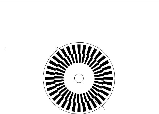
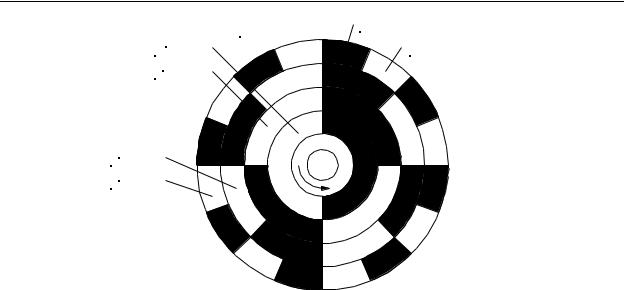
Consider the slotted disk mechanism described previously, but with the disk replaced by the one shown in Figure 9-28. This is a clear glass disk with black regions etched into the glass surface. For this device, we will have two light emitters on one side of the disk and two corresponding photo-transistors on the opposite side. The phototransistors will be positioned so that one receives light through the outer ring of segments
(the phase A segments) and the other receives light through the inner ring of segments
9-28
Chapter 9 - Encoders, Transducers, and Advanced Sensors
(the phase B segments). Our example encoder has 36 segments in each ring with the inner ring being skewed by 1/2 of a segment width in the clockwise direction.
Note: The encoder disk shown in Figure 9-28 is for illustrative purposes only and has been simplified in order to make the principle of operation easier to understand. Although the principle of operation is the same, actual incremental encoder disks are made differently from this illustration.
PHASE "A" SECTIONS
PHASE "B" SECTIONS
Figure 9-28 - 10° Optical Incremental Encoder Disk
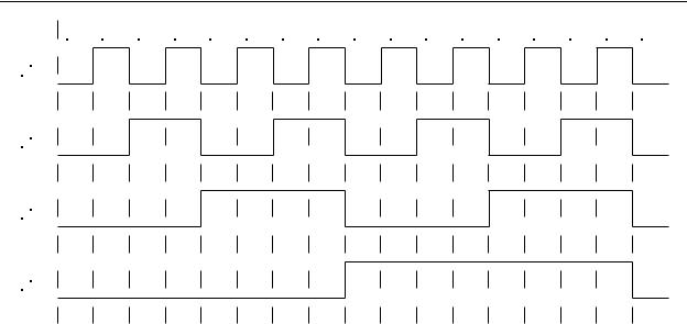
As the disk is rotated, the two photo-transistors will be exposed to light while a clear area of the disk passes, and light will be cut off to the photo-transistors while a dark area of the disk passes. If the disk is rotated at a constant angular velocity, both of the phototransistors will produce a square wave signal. Assuming the two photo-transistors are aligned along the same radial line, as the disk is rotated counterclockwise, the square wave produced by the phase B photo-transistor (on the inner ring of segments) will appear to lag that of the phase A (outer) photo-transistor by approximately 90 electrical degrees. This is because of the offset in the phase B sections etched onto the disk. However, if the disk is rotated clockwise, the phase B squarewave will lead phase A by approximately 90 degrees. These relationships are shown in Figure 9-29.
9-29

Chapter 9 - Encoders, Transducers, and Advanced Sensors
Phase A |
|
|
|
|
|
|
|
|
|
|
|
|
|
|
|
|
Phase A |
|
|
|
|
|
|
|
|
|
|
|
|
|
|
|
|
||||
|
|
|
|
|
|
|
|
|
|
|
|
|
|
|
|
|
|
|
|
|
|
|
|
|
|
|
|
|
|
|
|
|
|
|
|
|
|
|
|
|
|
|
|
|
|
|
|
|
|
|
|
Phase B |
|
|
|
|
|
|
|
|
|
|
|
|
|
|
|
|
|
||||||
Phase B |
|
|
|
|
|
|
|
|
|
|
|
|
|
|
|
|
|
|
|
|
|
|
|
|
|
|
|
|
|
|
|
|
|
|
|||
|
|
|
|
|
|
|
|
|
|
|
|
|
|
|
|
|
|
|
|
|
|
|
|
|
|
|
|
|
|
|
|
|
|
||||
|
|
|
|
|
|
|
|
|
|
|
|
|
|
|
|
|
|
|
|
|
|
|
|
|
|
|
|
|
|||||||||
|
|
|
|
|
Counterclockwise |
|
|
|
|
|
|
|
|
|
Clockwise |
|
|
|
|
|
|
|
|
||||||||||||||
Figure 9-29 - Incremental Encoder Output Waveforms
Incremental encoders are specified by the number of pulses per revolution that is produced by either the phase A or phase B output. By dividing the number of pulses per revolution into 360 degrees, we get the number of degrees per pulse (called the resolution). This is the smallest change in shaft angle that can be detected by the encoder. For example, a 3600 pulse incremental encoder has a resolution of 360 degrees / 3600 = 0.1 degree.
An incremental encoder can be used to extract three pieces of information about a rotating shaft. First, by counting the number of pulses received and multiplying the count by the encoder’s resolution, we can determine how far the shaft has been rotated in degrees. Second, by viewing the phase relationship between the phase A and phase B outputs, we can determine which direction the shaft is being rotated. Third, by counting the number of pulses received from either output during a fixed time period, we can calculate the angular velocity in either radians per second or RPMs.
When an incremental encoder is switched on, it simply outputs a 1 or 0 on its phase A and phase B output lines. This does not give any initial information about the angular position of the encoder shaft. In other words, the incremental encoder gives relative position information, with the reference position being the angle of the shaft when the encoder was energized. The only way an incremental encoder can be used to provide absolute position information is for the encoder shaft to be homed after it is powered-up.
This requires some other external device (such as a slotted disk) to provide this home position reference. Some incremental encoders have a third output signal named home that provides one pulse per revolution and can be used for homing the encoder.
Some incremental optical encoders are designed so that the phase A output will lead the phase B output when the encoder shaft is turned counterclockwise (as with our example) when viewed from the shaft end. However, others operate in just the opposite way. Therefore, designers should consult the technical data for the particular encoder being used. Keep in mind however that should the phase relationship between the phase A and phase B outputs be wrong, it is easily fixed by either swapping the two connections, or by inverting one of the two signals.
9-30

Chapter 9 - Encoders, Transducers, and Advanced Sensors
Example Problem:
A 2880 pulse per revolution incremental encoder is connected to a shaft. Its phase A outputs 934 pulses when the shaft is moved to a new position. What is the change in angle in degrees?
Solution:
The resolution of the encoder is 360 degrees / 2880 = 0.125 degree per pulse. Therefore the angle change is 0.125 x 934 = 116.75 degrees
Example Problem:
A 1440 pulse per revolution incremental encoder outputs an 1152 Hz square wave from phase A. How fast is the encoder shaft turning in RPMs?
Solution:
First calculate the rotating speed in revolutions per second. Since the encoder outputs 1152 pulses per second, it is rotating at 1152 / 1440 = 0.8 revolution per second. Now multiply this by 60 seconds to get the rotating speed in RPMs which is 0.8 x 60 = 48 RPMs.
Absolute Encoder
Unlike the incremental encoder, the absolute encoder provides digital values as an output signal. The output is in the form of a binary word which is proportional to the angle of the shaft. The absolute encoder does not need to be homed because when it is energized, it simply outputs the shaft angle as a digital value.
The absolute encoder is constructed similar to the incremental encoder in that is has an etched glass circular disk with opto-emitters and photo-transistors to detect the clear and opaque areas in the disk. However, the disk has a different pattern etched into it, as shown in Figure 9-30 (note that this is for illustrative purposes only - a 4-bit encoder is of little practical use). The pattern is a simple binary count pattern that has been curved into a circular shape. For the disk shown there are 4 distinct rings of patterns, each identified with a numerical weight that is a power of 2.
9-31
Chapter 9 - Encoders, Transducers, and Advanced Sensors
2 |
Shaft |
Opaque "0" Area |
3Ring |
Clear "1" Area |
|
22Ring |
|
|
21Ring
20Ring
Figure 9-30 - 4-Bit Binary Optical Absolute Encoder Disk
The encoder is constructed so that there is one photo-transistor aligned with each ring on the glass disk. As the shaft and disk are rotated, the photo-transistors output the binary pattern that is etched into the disk. For the disk shown, assuming the shaft is rotated counterclockwise, the output signals would appear as shown in Figure 9-31. Since the encoder disk layout is for 4-bit binary, one revolution of the disk causes an output of 16 different binary patterns. This means that each of the 16 patterns will cover an angular range of (360 degrees) / 16 = 22.5 degrees. This range of coverage for each output pattern is called the angular resolution. The absolute angle of the encoder shaft can be found by multiplying the binary output of the encoder times the resolution. For example, assume our
4-bit encoder has an output of 11012 (decimal 13). The encoder shaft would therefore be at an angle of 13 x 22.5 degrees = 292.5 degrees. Because of the relatively poor resolution of this encoder, the shaft could be at some angle between 292.5 degrees and 292.5+22.5 degrees.
9-32
Chapter 9 - Encoders, Transducers, and Advanced Sensors
0 |
|
1 |
|
2 |
|
3 |
|
4 |
|
5 |
|
6 |
|
7 |
|
8 |
|
9 |
|
10 |
|
11 |
|
12 |
|
13 |
|
14 |
|
15 |
|
0 |
|
|
|
|
|
|
|
|
|
|
|
|
|
|
|
|
20
21
22
23
Figure 9-31 - 4-Bit Binary Encoder Output Signals
Example Problem:
A 12 bit binary absolute encoder is outputting the number 101100010111. a) What is the resolution of the encoder, and b) what is the range of angles indicated by its output.
Solution:
a)A 12 bit encoder will output 212 binary numbers for one revolution. Therefore the resolution is 360 degrees / 212 = 0.087891 degree.
b)Converting the binary number to decimal, we have 1011000101112 = 283910. The
indicated angle is between 2839 x 0.087891 = 249.52 degrees and
249.52 + 0.087891 = 249.60 degrees.
One inherent problem that is encountered with binary output absolute encoders occurs when the output of the encoder changes its value. Consider our 4-bit binary encoder when it changes from 7 (binary 0111) to 8 (binary 1000). Notice that in this case, the state of all four of its output bits change value. If we were to capture the output of the encoder while these four outputs are changing state, it is likely that we will read an erroneous value. The reason for this is that because of the variations in slew rates of the photo-transistors and any small alignment errors in the relative positions of the phototransistors, it is unlikely that all four of the outputs will change at exactly the same instant.
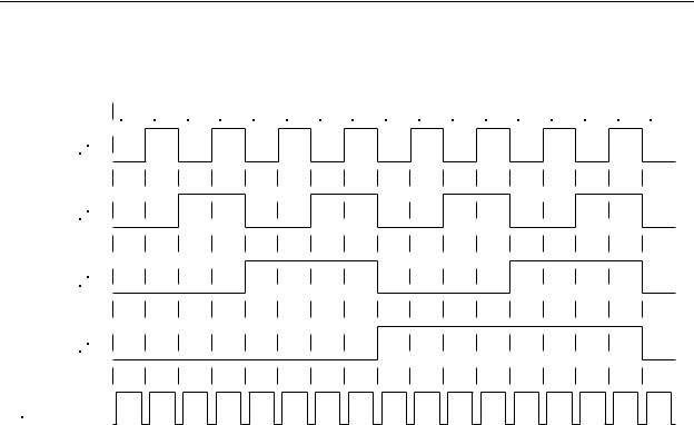
For this reason, all binary output encoders include one additional output line called data valid (also called data available, or strobe). This is an output that, as the encoder is
9-33
Chapter 9 - Encoders, Transducers, and Advanced Sensors
rotated, goes false for the very short instant while the outputs are changing state. As soon as the outputs are settled, the data valid line goes true, indicating that it is safe to read the data. This is illustrated in the timing diagram in Figure 9-32.
0 |
|
1 |
|
2 |
|
3 |
|
4 |
|
5 |
|
6 |
|
7 |
|
8 |
|
9 |
|
10 |
|
11 |
|
12 |
|
13 |
|
14 |
|
15 |
|
0 |
|
|
|
|
|
|
|
|
|
|
|
|
|
|
|
|
20
21
22
23
Data Valid
Figure 9-32 - 4-Bit Binary Encoder Output Signals
with Data Valid Signal
It is possible to purchase an absolute encoder that does not need a data valid output signal (nor does it have one). In some applications, this is more convenient because it requires one less signal line from the encoder to the PLC (or computer), and the PLC (or computer) can read the encoder output at any time without error. This is done by using a special output coding method that is called gray code. Gray code requires the same number of bits to achieve the same resolution as a binary encoder equivalent; however, the counting pattern is established so that, as the angle increases or decreases, no more than one output bit changes at a given time. Many present-day PLCs include math functions to convert gray code to binary, decimal, octal, or hexadecimal.
Like binary code, gray code starts with 000...000 as the number “zero”, and 000...001 as the number “one”. However, from this point, gray code takes a different direction and is unlike binary. Converting from gray code to binary and vise versa is relatively easy by following a few simple steps.
9-34

Chapter 9 - Encoders, Transducers, and Advanced Sensors
Converting Binary to Gray:
1.Write the binary number to be converted and add a leading zero (on the left side).
2.Exclusive-OR each pair of bits in the binary number together and write the resulting bits below the original number.
Example:
Convert 10011100102 to gray code.
Solution:
Step 1 - 01001110010 (add a leading zero)
Step 2 - exclusive-OR adjacent bits
0 1 0 0 1 1 1 0 0 1 0 binary w w w w w w w w w w
1 1 0 1 0 0 1 0 1 1 gray
Converting Gray to Binary:
1.Write the gray code number to be converted and add a leading zero (on the left side).
2.Beginning with the leftmost digit (the added zero), perform a chain addition of all the bits, writing the "running sum" as you go (discard all carrys).
9-35

Chapter 9 - Encoders, Transducers, and Advanced Sensors
Example:
Convert 1101001011 gray to binary.
Solution:
Step 1 - 01101001011G (add a leading zero)
Step 2 - 0 +1=1 +1=0 +0=0 +1=1 +0=1 +0=1 +1=0 +0=0 +1=1 +1=0
The equivalent binary number is 10011100102
It is extremely important to remember that whenever converting gray to binary, or binary to gray, the total number of bits before and after the conversions must be the same. For example, a 16-bit gray code number will always convert to a 16-bit binary number and vise versa.
It may seem that gray code would have the same inherent problem with read errors as binary code if data is read while the encoder output is transitioning. However, remember that in gray code, any two adjacent values differ by only one bit change. This means that even if a PLC were to read the data while it is changing, the only possible error will be in the single transitioning bit. Therefore, the only possibility is that the PLC will read the number as one of the two adjacent numbers, hardly a gross error. Therefore, it is unnecessary to strobe the output of a gray code absolute encoder.
Example Problem:
A 10-bit gray code optical encoder is outputting the number 0011100101. What is the indicated angle?
9-36