


Chapter 9 - Encoders, Transducers, and Advanced Sensors
9-6. Pressure/Vacuum
Since many machine systems use pneumatic (air) pressure, vacuum, or hydraulic pressure to perform certain tasks, it is necessary to be able to sense the presence of pressure or vacuum, and in many cases, to be able to measure the magnitude of the pressure or vacuum. Next we will discuss some of the more popular methods for the discrete detection and the analog sensing of pressure and vacuum.
Bellows Switch
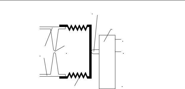
The bellows switch is a relatively simple device that provides a discrete (on or off) signal based on pressure. Referring to Figure 9-12, notice that the bellows (which is made of a flexible material, usually rubber) is sealed to the end of a pipe from which the pressure is to be sensed. When the pressure in the pipe increases, the bellows pushes on the actuator of a switch. When the pressure increases to a point where the bellows overcomes the switch’s actuator spring force, the switch actuates, the N/O contact connects to the common, and the N/O contact disconnects from the common.
Generally, for most pressure sensing switches and sensors, a pressure hammer orifice is included in the device. This is done to protect the device from extreme pressure transients (called pressure hammer) caused by the opening and closing of valves elsewhere in the system which could rupture the bellows. Pressure hammer is most familiar to us when we quickly turn off a water faucet and hear the pipes in the home bang from the transient pressure. The orifice is simply a constriction in the pipe’s inner diameter so that air or fluid inside the pipe is prevented from flowing rapidly into the bellows.
9-13
Chapter 9 - Encoders, Transducers, and Advanced Sensors
Switch
Actuator
Momentary
Pushbutton
Switch
|
Pressure |
N/C |
|
|
|
||
Pipe |
Hammer |
|
|
Orifice |
N/O |
||
Wall |
|||
|
|
Bellows |
|
Com |
|
||
|
|
Figure 9-12 - Bellows-Type Pressure Switch
Cross Section
The pressure at which the bellows switch actuates is difficult to predict because, in addition to pressure, it also depends on the elasticity of the bellows, the spring force in the switch, and the mechanical friction of the actuator. Therefore, these types of switches are generally used for coarse pressure sensing. The most common use is to simply detect the presence or absence of pressure on the system so that a controller (PLC) can determine if a pump has failed.
Because of the frailty of the rubber bellows, bellows switches cannot be used to sense high pressures. For high pressure applications, the bellows is replaced by a diaphragm made of a flexible material (nylon, aluminum, etc.) that deforms (bulges) when high pressure is applied. This deformation presses on the actuator of a switch.
The N/O and N/C electrical symbols for the pressure switch are shown in Figure 9-13. The semicircular symbol connected to the switch arm symbolizes a pressure diaphragm. Generally, temperature switches are drawn in the state they would take at
1 atmosphere of pressure (i.e., atmospheric pressure at sea level). Therefore, a N/O pressure switch as shown on the left of Figure 9-13 would close at some pressure higher than 0 psig, and the N/C switch on the right side of Figure 9-13 would open at some pressure higher then 0 psig. Also, if the switch actuates at a fixed pressure, or setpoint, we usually write the setpoint pressure next to the switch as shown next to the N/C switch in Figure 9-13. This switch would open at 300 psig.
9-14
Chapter 9 - Encoders, Transducers, and Advanced Sensors
300psi
Figure 9-13 - Discrete Output
Pressure Switch Symbols
Strain gage pressure sensor
The strain gage pressure sensor is the most popular method of making analog measurements of pressure. It is relatively simple, reliable, and accurate. It operates on the principle that whenever fluid pressure is applied to any solid material, the material deforms (strains). If we know the strain characteristics of the material and we measure the strain, we can calculate the applied pressure.
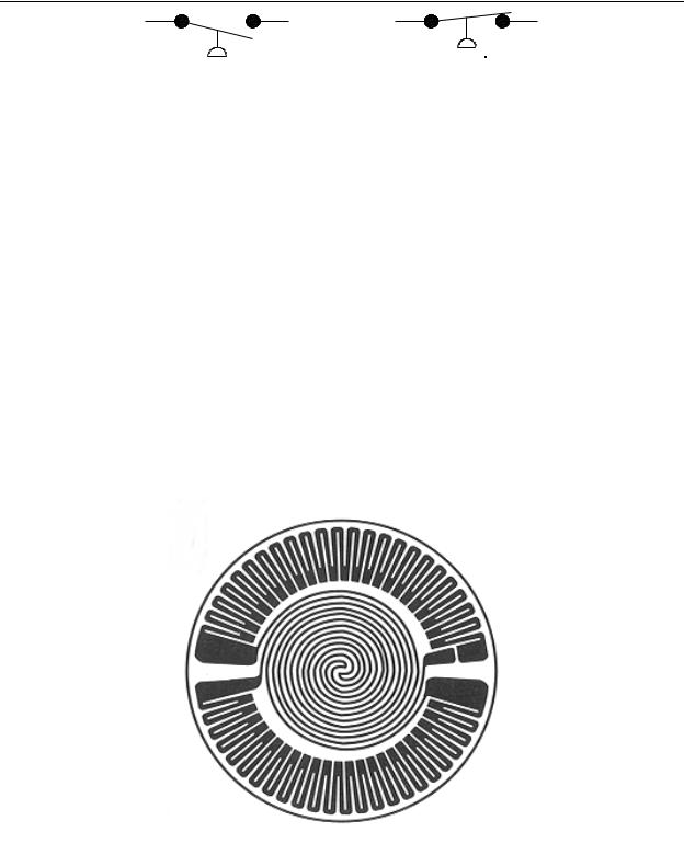
For this type of measurement, a different type of strain gage is used, as shown in Figure 9-14. This strain gage measures radial strain instead of longitudinal strain. Notice that there are two different patterns of strain conductors on this strain gage. The pair around the edge of the gage (we will call the “outer gages”) appear as regular strain gages but in a curved pattern. Then there are two spiral gage patterns in the center of the gage (we will call the “inner gages”). As we will see, each pattern serves a specific purpose in contributing to the pressure measurement.
Figure 9-14 - Diaphragm Strain Gage
(Omega Instruments)
9-15
Chapter 9 - Encoders, Transducers, and Advanced Sensors
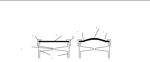
If we were to glue the diaphragm strain gage to a metal disk with known stress/strain characteristics, and then seal the assembly to the end of a pipe, we would have a unit as is appears in Figure 9-15a. The strain gage and disk assembly are mounted to the pipe with the strain gage on the outside (in Figure 9-15a, the top).
|
|
|
Tension |
Seal |
Diaphragm |
Compression |
Compression |
Strain Gage |
Seal |
|
|
|
|
|
Pressure |
|
Hammer |
|
Orifice |
|
Pipe |
|
Wall |
|
(a) |
(b) |
Figure 9-15 - Strain Gage Pressure Gage Cross Section
(a) 1 Atmosphere, (b) >1 Atmosphere
When pressure is applied to the inside of the pipe, the disk and strain gage begin to bulge slightly outward as shown in Figure 9-15b (an exaggerated illustration). The amount of bulging is proportional to the inside pressure. Referring to Figure 9-15b, notice that the top surface of the disk will be in compression around the outer edge (where the outer gages are located), and will be in tension near the center (where the inner gages are located). Therefore, when pressure is applied, the resistance of the outer gages will decrease and the resistance of the inner gages will increase.
If we follow the conductor patterns on the diaphragm in Figure 9-14, we see that they are connected in a Wheatstone bridge arrangement (the reader is encouraged to trace the patterns and draw an electrical diagram). If we connect the gages as shown in
Figure 9-16, we can measure the strain (and therefore the pressure) by measuring the voltage difference Va-Vb. When pressure is applied, since the resistance of the outer gages will decrease and the resistance of the inner gages will increase, the voltage Va will increase and the voltage Vb will decrease, which will unbalance the bridge. The voltage difference Va-Vb will be positive indicating positive pressure.
9-16
Chapter 9 - Encoders, Transducers, and Advanced Sensors
Outer gage |
|
Inner Gage |
|
Va |
Vb |
Av |
Av(Va-Vb) |
Inner Gage |
|
Outer gage |
|
|
|
Instrumentation Amplifier |
|
Figure 9-16 - Strain Gage Pressure Gage Electrical Connection
If a vacuum is applied to the sensor, the disk and strain gage will deform (bulge) inward. This causes an exact opposite effect in all the resistance values which will produce a negative voltage output from the Wheatstone bridge.
Many strain gage type pressure sensors (also called pressure transducers) are available with the instrumentation amplifier included inside the sensor housing. The entire unit is calibrated to produce a precise output voltage proportional to pressure. These units have an output that is usually specified as a calibration factor in psi/volt.
Example Problem:
A 0 to +250psi pressure transducer has a calibration factor of 25psi/volt. a) What is the pressure if the transducer output is 2.37 volts? b) What is the full scale output voltage of the transducer?
Solution:
a)When working a problem of this type, dimensional analysis helps. The calibration factor is in psi/volt and the output is in volts. If we multiply psi/volt times volts, we get psi, the desired unit for the solution. Therefore, the pressure is 25psi/volt x 2.37 v = 59.25psi.
b)The full scale output voltage is 250psi / 25psi/volt = 10 volts.
Variable Reluctance Pressure Sensor
Another method for measuring pressure and vacuum that is more sensitive than most other methods is the variable reluctance pressure sensor (or transducer). This unit operates similarly to the linear variable differential transformer (LVDT) discussed later in this chapter. Consider the cross section illustration of the variable reluctance pressure sensor shown in Figure 9-17. Two identical coils (same dimensions, same number of turns, same size wire) are suspended on each side of a ferrous diaphragm disk. The disk is
9-17