


Chapter 1 - Ladder Diagram Fundamentals
Chapter 1 - Ladder Diagram Fundamentals
1-1. Objectives
Upon completion of this chapter, you will be able to
”identify the parts of an electrical machine control diagram including rungs, branches, rails, contacts, and loads.
”correctly design and draw a simple electrical machine control diagram.
”recognize the difference between an electronic diagram and an electrical machine diagram.
”recognize the diagramming symbols for common components such as switches, control transformers, relays, fuses, and time delay relays.
”understand the more common machine control terminology.
1-2. Introduction
Machine control design is a unique area of engineering that requires the knowledge of certain specific and unique diagramming techniques called ladder diagramming. Although there are similarities between control diagrams and electronic diagrams, many of the component symbols and layout formats are different. This chapter provides a study of the fundamentals of developing, drawing and understanding ladder diagrams. We will begin with a description of some of the fundamental components used in ladder diagrams.
The basic symbols will then be used in a study of boolean logic as applied to relay diagrams. More complicated circuits will then be discussed.
1-3. Basic Components and Their Symbols
We shall begin with a study of the fundamental components used in electrical machine controls and their ladder diagram symbols. It is important to understand that the material covered in this chapter is by no means a comprehensive coverage of all types of machine control components. Instead, we will discuss only the most commonly used ones.
Some of the more exotic components will be covered in later chapters.
Control Transformers
For safety reasons, machine controls are low voltage components. Because the switches, lights and other components must be touched by operators and maintenance personnel, it is contrary to electrical code in the United States to apply a voltage higher than
1-1
Chapter 1 - Ladder Diagram Fundamentals
120VAC to the terminals of any operator controls. For example, assume a maintenance person is changing a burned-out indicator lamp on a control panel and the lamp is powered by 480VAC. If the person were to touch any part of the metal bulb base while it is in contact with the socket, the shock could be lethal. However, if the bulb is powered by
120VAC or less, the resulting shock would likely be much less severe.
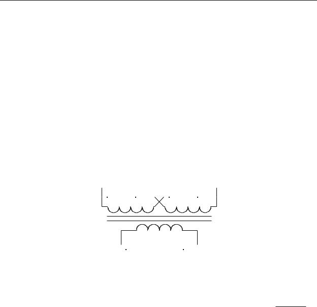
In order to make large powerful machines efficient and cost effective and reduce line current, most are powered by high voltages (240VAC, 480VAC, or more). This means the line voltage must be reduced to 120VAC or less for the controls. This is done using a control transformer. Figure 1-1 shows the electrical diagram symbol for a control transformer. The most obvious peculiarity here is that the symbol is rotated 90° with the primaries on top and secondary on the bottom. As will be seen later, this is done to make it easier to draw the remainder of the ladder diagram. Notice that the transformer has two primary windings. These are usually each rated at 240VAC. By connecting them in parallel, we obtain a 240VAC primary, and by connecting them in series, we have a
480VAC primary. The secondary windings are generally rated at 120VAC, 48VAC or 24VAC. By offering control transformers with dual primaries, transformer manufacturers can reduce the number of transformer types in their product line, make their transformers more versatile, and make them less expensive.
H1 H3 
 H2 H4
H2 H4
X1 X2
Figure 1-1 - Control Transformer
Fuses
Control circuits are always fuse protected. This prevents damage to 


 the control transformer in the event of a short in the control circuitry. The
electrical symbol for a fuse is shown in Figure 1-2. The fuse used in control circuits is generally a slo-blow fuse (i.e. it is generally immune to current
transients which occur when power is switched on) and must be rated at a current that is less than or equal to the rated secondary current of the control transformer, and it must be connected in series with the transformer secondary. Most control transformers can be purchased with a fuse block (fuse holder) for the secondary fuse mounted on the transformer, as shown in Figure 1-3.
1-2

Chapter 1 - Ladder Diagram Fundamentals
Figure 1-3 - Control Transformer with
Secondary Fuse Holder
(Allen Bradley)
Switches
There are two fundamental uses for switches. First, switches are used for operator input to send instructions to the control circuit. Second, switches may be installed on the moving parts of a machine to provide automatic feedback to the control system. There are many different types of switches, too many to cover in this text. However, with a basic understanding of switches, it is easy to understand most of the different types.
Pushbutton
The most common switch is the pushbutton. It is also the one that needs the least description because it is widely used in automotive and electronic equipment applications. There are two types of pushbutton, the momentary and maintained. The momentary pushbutton switch is activated when the button is pressed, and deactivated when the button is released. The deactivation is done using an internal spring. The maintained pushbutton activates when pressed, but remains activated when it is released. Then to deactivate it, it must be pressed a second time. For this reason, this type of switch is sometimes called a push-push switch. The on/off switches on most desktop computers and laboratory oscilloscopes are maintained pushbuttons.
1-3

The schematic symbol for the maintained pushbutton is shown in Figure 1-5. Note that it is the symbol for the momentary pushbutton with a “see-saw” mechanism added to hold in the switch actuator until it is pressed a second time. As with the momentary switch, the maintained switch can have as many contacts of either type as desired.
Pushbutton Switch Actuators
Figure 1-5 -
Maintained Switch
The actuator of a pushbutton is the part that you depress to activate the switch.
These actuators come is several different styles as shown in Figure 1-6, each with a specific purpose.
The switch on the left in Figure 1-6 has a guarded or shrouded actuator. In this case the pushbutton is recessed 1/4"-1/2" inside the sleeve and can only be depressed by an object smaller than the sleeve (such as a finger). It provides protection against the button being accidentally depressed by the palm of the hand or other object and is therefore used in situations where pressing the switch causes something potentially dangerous to happen. Guarded pushbuttons are used in applications such as START,
RUN, CYCLE, JOG, or RESET operations. For example, the RESET pushbutton on your computer is likely a guarded pushbutton.
The switch shown in the center of Figure 1-6 has an actuator that is aligned to be even with the sleeve. It is called a flush pushbutton. It provides similar protection against accidental actuation as the guarded pushbutton; however, since it is not recessed, the level of protection is not to the extent of the guarded pushbutton. This type of switch actuator works better in applications where it is desired to back light the actuator (called a lighted pushbutton).
1-4

Chapter 1 - Ladder Diagram Fundamentals
The switch on the right is an extended pushbutton. Obviously, the actuator extends beyond the sleeve which makes the button easy to depress by finger, palm of the hand, or any object. It is intended for applications where it is desirable to make the switch as accessible as possible such as STOP, PAUSE, or BRAKES.
Figure 1-6 - Switch Actuators
The three types of switch actuators shown in Figure 1-6 are not generally used for applications that would be required in emergency situations nor for operations that occur hundreds of times per day. For both of these applications, a switch is needed that is the most accessible of all switches. These types are the mushroom head or palm head pushbutton (sometimes called palm switches, for short), and are illustrated in Figure 1-7.
Figure 1-7 - Mushroom Head Pushbuttons
Although these two applications are radically different, the switches look similar. The mushroom head switch shown on the left of Figure 1-7 is a momentary switch that may be used to cause a machine run one cycle of an operation. For safety reasons, they are usually used in pairs, separated by about 24", and wired so that they must both be pressed at the same time in order to cause the desired operation to commence. When arranged and wired such as this, we create what is called a 2-handed palming operation. By doing
1-5
Chapter 1 - Ladder Diagram Fundamentals
so, we know that when the machine is cycled, the operator has both hands on the pushbuttons and not in the machine.
The switch on the right of Figure 1-7 is a detent pushbutton (i.e. when pressed in it remains in, and then to return it to its original position, it must be pulled out) and is called an Emergency Stop, or E-Stop switch. The mushroom head is always red and the switch is used to shutoff power to the controls of a machine when the switch is pressed in. In order to restart a machine, the E-Stop switch must be pulled to the out position to apply power to the controls before attempting to run the machine.
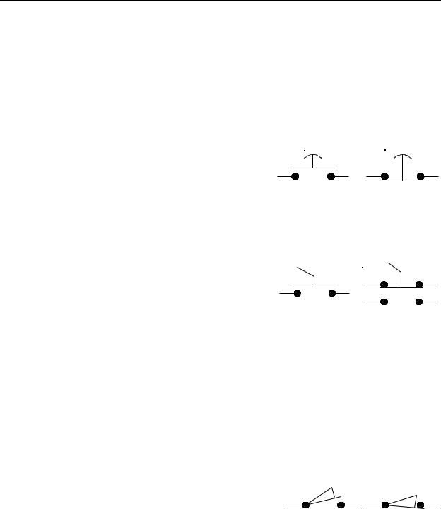
Mushroom head switches have special |
RUN |
E-STOP |
schematic symbols as shown in Figure 1-8. Notice that |
|
|
they are drawn as standard pushbutton switches but |
|
|
have a curved line on the top of the actuators to indicate Figure 1-8 - Mushroom Switches |
|||
that the actuators have a mushroom head. |
|
|
|
Selector Switches |
|
|
|
A |
selector switch is also known as a rotary |
STOP |
RUN |
switch. |
An automobile ignition switch, and an |
|
|
oscilloscope’s vertical gain and horizontal timebase |
|
|
|
switches are examples of selector switches. Selector |
Figure 1-9 - Selectors |
||
switches |
use the same symbol as a momentary |
||
pushbutton, except a lever is added to the top of the actuator, as shown in Figure 1-9. The switch on the left is open when the selector is turned to the left and closed when turned to the right. The switch on the right side has two sets of contacts. The top contacts are closed when the switch selector is turned to the left position and open when the selector is turned to the right. The bottom set of contacts work exactly opposite. There is no electrical connection between the top and bottom pairs of contacts. In most cases, we label the selector positions the same as the labeling on the panel where the switch is located. For the switch on the right in Figure 1-9, the control panel would be labeled with the STOP position to the left and the RUN position to the right.
Limit Switches
Limit switches are usually not operator accessible.
Instead they are activated by moving parts on the machine. They are usually mechanical switches, but can
also be light activated (such as the automatic door Figure 1-10 - Limit Switches openers used by stores and supermarkets), or magnetically operated (such as the magnetic switches used on home security systems that sense when a window has been opened). An example of a mechanically operated limit switch is the switch on the
1-6

Chapter 1 - Ladder Diagram Fundamentals
refrigerator door that turns on the light inside. They are sometimes called cam switches because many are operated by a camming action when a moving part passes by the switch. The symbols for both types of limit switches are shown in Figure 1-10. The N/O version is on the left and the N/C version is on the right. One of the many types of limit switch is pictured in Figure 1-11.
Figure 1-11 - Limit Switch
Indicator Lamps
All control panels include indicator lamps. They tell the operator |
|
when power is applied to the machine and indicate the present operating |
|
status of the machine. Indicators are drawn as a circle with “light rays” |
|
extending on the diagonals as shown in Figure 1-12. |
Figure 1-12 - |
|
Lamp |
Although the light bulbs used in indicators |
are generally |
incandescent (white), they are usually covered with colored lenses. The colors are usually red, green, or amber, but other colors are also available. Red lamps are reserved for safety critical indicators (power is on, the machine is running, an access panel is open, or that a fault has occurred). Green usually indicates safe conditions (power to the motor is off, brakes are on, etc.). Amber indicates conditions that are important but not dangerous (fluid getting low, machine paused, machine warming up, etc.). Other colors indicate information not critical to the safe operation of the machine (time for preventive maintenance, etc.). Sometimes it is important to attract the operator’s attention with a lamp. In these cases, we usually flash the lamp continuously on and off.
Relays
Early electrical control systems were composed of mainly relays and switches.
Switches are familiar devices, but relays may not be so familiar. Therefore, before
1-7
Chapter 1 - Ladder Diagram Fundamentals
continuing our discussion of machine control ladder diagramming, a brief discussion of relay fundamentals may be beneficial. A simplified drawing of a relay with one contact set is shown in Figure 1-13. Note that this is a cutaway (cross section) view of the relay.
NORMALLY CLOSED CONDUCTOR |
INSULATOR |
NORMALLY CLOSED |
|
(N/C) CONTACT |
(N/C) CONTACT |
MOVABLE CONTACT |
|
INSULATOR |
|
|
|
NORMALLY OPEN |
|
NORMALLY OPEN |
(N/O) CONTACT |
|
(N/O) CONTACT |
PLUNGER |
|
INSULATOR |
|
|
|
|
CORE |
COIL |
|
SPRING |
|
|
|
Figure 1-13 - Relay or Contactor
A relay, or contactor, is an electromagnetic device composed of a frame (or core) with an electromagnet coil and contacts (some movable and some fixed). The movable contacts (and conductor that connects them) are mounted via an insulator to a plunger which moves within a bobbin. A coil of copper wire is wound on the bobbin to create an electromagnet. A spring holds the plunger up and away from the electromagnet. When the electromagnet is energized by passing an electric current through the coil, the magnetic field pulls the plunger into the core, which pulls the movable contacts downward. Two fixed pairs of contacts are mounted to the relay frame on electrical insulators so that when the movable contacts are not being pulled toward the core (the coil is de-energized) they physically touch the upper fixed pair of contacts and, when being pulled toward the coil, touches the lower pair of fixed contacts. There can be several sets of contacts mounted to the relay frame. The contacts energize and de-energize as a result of applying power to the relay coil (connections to the relay coil are not shown). Referring to Figure 1-13, when the coil is de-energized, the movable contacts are connected to the upper fixed contact pair. These fixed contacts are referred to as the normally closed contacts because they are bridged together by the movable contacts and conductor whenever the relay is in its "power off" state. Likewise, the movable contacts are not connected to the lower fixed contact pair when the relay coil is de-energized. These fixed contacts are referred to as the normally open contacts. Contacts are named with the relay in the deenergized state. Normally open contacts are said to be off when the coil is de-energized and on when the coil is energized. Normally closed contacts are on when the coil is deenergized and off when the coil is energized. Those that are familiar with digital logic tend to think of N/O contacts as non-inverting contacts, and N/C contacts as inverting contacts.
1-8
Chapter 1 - Ladder Diagram Fundamentals
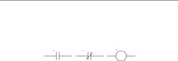
It is important to remember that many of the schematic symbols used in electrical diagrams are different than the symbols for the same types of components in electronic diagrams. Figure 1-14 shows the three most common relay symbols used in electrical machine diagrams. These three symbols are a normally open contact, normally closed contact and coil. Notice that the normally open contact on the left could easily be misconstrued by an electronic designer to be a capacitor. That is why it is important when working with electrical machines to mentally “shift gears” to think in terms of electrical symbols and not electronic symbols.
CR1 |
CR101 |
CR1 |
Figure 1-14 - Relay Symbols
Notice that the normally closed and normally open contacts of Figure 1-14 each have lines extending from both sides of the symbol. These are the connection lines which, on a real relay, would be the connection points for wires. The reader is invited to refer back to Figure 1-13 and identify the relationship between the normally open and normally closed contacts on the physical relay and their corresponding symbols in Figure 1-14.
The coil symbol shown in Figure 1-14 represents the coil of the relay we have been discussing. The coil, like the contacts, has two connection lines extending from either side. These represent the physical wire connections to the coil on the actual relay. Notice that the coil and contacts in the figure each have a reference designator label above the symbol. This label identifies the contact or coil within the ladder diagram. Coil CR1 is the coil of relay CR1. When coil CR1 is energized, all the normally open CR1 contacts will be closed and all the normally closed CR1 contacts will be open. Likewise, if coil CR1 is deenergized, all the normally open CR1 contacts will be open and all the normally closed CR1 contacts will be closed. Most coils and contacts we will use will be labeled as CR (CR is the abbreviation for “control relay”). A contact labeled CR indicates that it is associated with a relay coil. Each relay will have a specific number associated with it. The range of numbers used will depend upon the number of relays in the system.
Figure 1-15 shows the same relay symbols as in Figure 1-14, however, they have not been drawn graphically. Instead they are drawn using standard ASCII printer characters (hyphens, vertical bars, forward slashes, and parentheses). This is a common method used when the ladder diagram is generated by a computer on an older printer, or when it is desired to rapidly print the ladder diagram (ASCII characters print very quickly). This printing method is usually limited to ladder diagrams of PLC programs as we will see later. Machine electrical diagrams are rarely drawn using this method.
1-9

Chapter 1 - Ladder Diagram Fundamentals
CR1 |
CR101 |
CR1 |
----| |---- |
----|/|---- |
----( )---- |
Figure 1-15 - ASCII Relay Symbols
Relays can range in size from extremely small reed relays in 14 pin DIP integrated circuit-style packages capable of switching a few tenths of an ampere at less than 100 volts to large contactors the size of a room capable of switching thousands of amperes at thousands of volts. However, for electrical machine diagrams, the schematic symbol for a relay is the same regardless of the relay’s size.
Time Delay Relays
It is possible to construct a relay with a built-in time delay device that causes the relay to either switch on after a time delay, or to switch off after a time delay. These types of relays are called time delay relays, or TDR’s. The schematic symbols for a TDR coil and contacts are the same as for a conventional relay, except that the coil symbol has the letters “TDR” or “TR” written inside, or next to the coil symbol. The relay itself looks similar to any other relay except that it has a control knob on it that allows the user to set the amount of time delay. There are two basic types of time delay relay. They are the delay-on timer, sometimes called a TON (pronounced Tee-On), and the delay off timer, sometimes called a TOF (pronounced Tee-Off). It is important to understand the difference between these relays in order to specify and apply them correctly.
Delay-On Timer (TON) Relay
When an on-timer is installed in a circuit, the user adjusts the control on the relay for the desired time delay. This time setting is called the preset. Figure 1-16 shows a timing diagram of a delay-on time delay relay. Notice on the top waveform that we are simply turning on power to the relay’s coil and some undetermined time later, turning it off (the amount of time that the coil is energized makes no difference to the operation of the relay). When the coil is energized, the internal timer in the relay begins running (this can be either a motor driven mechanical timer or an electronic timer). When the time value contained in the timer reaches the preset value, the relay energizes. When this happens, all normally open (N/O) contacts on the relay close and all normally closed (N/C) contacts on the relay open. Notice also that when power is removed from the relay coil, the contacts immediately return to their de-energized state, the timer is reset, and the relay is ready to begin timing again the next time power is applied. If power is applied to the coil and then switched off before the preset time is reached, the relay contacts never activate.
1-10