


Chapter 6 - Wiring Techniques
Chapter 6 - Wiring Techniques
6-1. Objectives
Upon completion of this chapter, you will know
”how to provide ac power to a PLC.
”various types of PLC input configurations.
”how to select the best PLC input configuration for an application.
”how to connect external components to PLC inputs.
”various types of PLC output configurations.
”how to select the best PLC output configuration for an application.
”how to connect PLC outputs to external components.
6-2. Introduction
A very important subject often overlooked in the study of programmable controllers is how to connect the PLC to the system being controlled. This involves connections of such devices as limit switches, proximity detectors, photoelectric detectors, external high current contactors and motor starters, lights and a vast array of other devices which can be utilized with the PLC to control or monitor systems. Wiring a device to the PLC involves the provision of proper power to the devices, sizing of wiring to insure current carrying capacity, routing of wiring for safety and to minimize interference, insuring that all connections are made properly and to the correct terminals, and providing adequate fusing to protect the system.
PLC systems typically involve the handling of circuitry operating at several different voltage and current levels. Power to the PLC and other devices may require the connection of 120 VAC while photoelectric and proximity devices may require 24 VDC. Motors being controlled by the PLC may operate at much higher voltage levels such as 240 or 480 VAC 3N. Current for photoelectric and proximity devices are in the range of milliamps while motor currents run much higher depending upon the size of the motor - 30 amps or more.
The PLC connections except for main power are confined to connecting inputs to sensing devices and switches and connecting outputs to devices being controlled (lamps, motor starters, contactors). This is the area this chapter will concentrate on since this is the main area of concern for the programmer. We will also touch on the other areas as required while discussing input and output connections.
6-1
Chapter 6 - Wiring Techniques
6-3. PLC Power Connection
The power requirement for the PLC being used will vary depending upon the model selected. PLC's are available that operate on a wide range of power typically 24 VDC, 120 VAC and 240 VAC. Some manufacturers produce units that will operate on any voltage from 120 VAC to 240 VAC without any modifications to the unit. Connection of power to the DC type units requires that careful attention be paid to insuring that the (+) and (-) power wires are correctly connected. Failure to do so can result in serious damage to the
PLC. Power connection to AC units is not so critical unless the PLC specifications may require specific connection of the hot and neutral wires to the proper terminals. However, no matter which style PLC is being utilized, proper fuses must be inserted in the power line connections to protect both the PLC and the power wiring from overcurrent either from accidental shorts or equipment failure causes. The installation manual for the particular
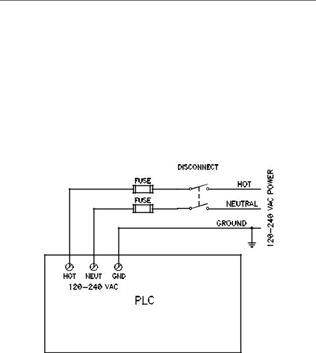
PLC being used will generally provide fusing information for that unit. The wiring diagram for an AC type PLC is shown in Figure 6-1.
Figure 6-1 - Typical AC Power Wiring
Notice that incoming power is first connected to a disconnect switch. This switch, when turned off, will disconnect all power from the fuses and the PLC. This provides safety for personnel performing maintenance on the system by totally removing power from the
6-2
Chapter 6 - Wiring Techniques
system. The neutral conductor is typically grounded at the source. If the neutral is grounded, the portion of the disconnect switch controlling the neutral is not required.
However, if the neutral ground is lost, it would be possible to receive a shock if the neutral wire were touched. For safety, it is always better to totally disconnect power. Two fuses are shown, one for hot and one for neutral. Again, if the neutral is grounded the neutral fuse is not required. However, for the same reason as the disconnect, the second fuse is desirable since it will protect the system against heavy neutral current that could result if the ground is lost. Some discussion of the terms hot and neutral may be required here.
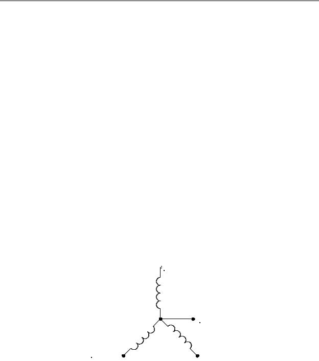
Utility power is generally generated as three phase (3N) voltage. This is accomplished by the wiring scheme in the generator which produces three voltage sources at a phase angle of 120° from each other. The schematic representation of this type of generator is shown in Figure 6-2. Notice that the generator has three windings - the outputs of which are labeled PHASE A, PHASE B and PHASE C. There is also a fourth terminal on the generator labeled NEUTRAL which is connected to the common connection of all three phase terminals. For this discussion, assume we are using 120 VAC 3N. If the generator of Figure 6-2 were producing this voltage, the following voltages would be present. The voltage from any PHASE (A, B or C) to NEUTRAL would be 120 VAC. The voltage between any two phases (PHASE A/PHASE B, PHASE B/PHASE C or PHASE C/PHASE A) would be 208 VAC. The three PHASE leads are referred to as the HOT leads and the common connection to all three phase windings is referred to as the NEUTRAL lead. In practice, the NEUTRAL connection is connected to earth ground at the generator.
This is true in residential and commercial buildings with 120 VAC power. The NEUTRAL wire in the building is connected to earth ground at the panel where power enters the building. For this reason, if a voltmeter were placed between the NEUTRAL wire and the safety ground wire in any receptacle, the voltage read would be close to or at 0 VAC.
 Phase A
Neutral
Phase C |
Phase B |
|
Figure 6-2 - 3-Phase Generator
Schematic
6-3
Chapter 6 - Wiring Techniques
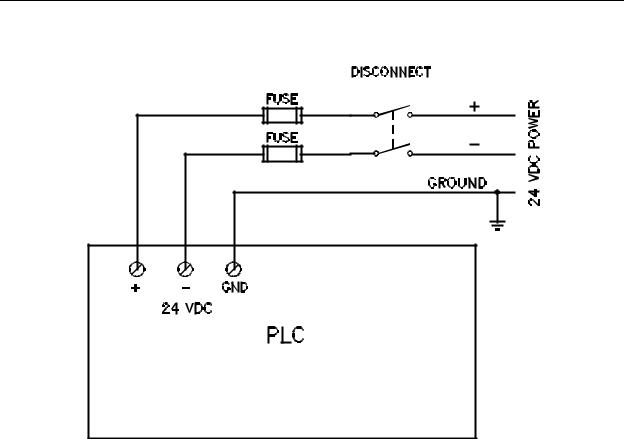
In some cases, PLCs are operated from DC power instead of AC power. Figure 6-3 illustrates the power connection for a PLC requiring DC power, in this case, 24 VDC.
Figure 6-3 - Typical DC Power Wiring
This wiring also includes fusing and disconnecting for both power conductors. If the (-) power line is grounded at the source, the (-) disconnect and fuse would not be required.
However, as with the AC power wiring, it is always safer to provide for fusing and disconnection of both power conductors.
Care must be taken to insure that the wiring is properly connected to avoid damage to the equipment and to the personnel coming into contact with it. For this reason, in this chapter, a very simplistic approach will be taken to describe wiring techniques. This may seem insulting to some readers but the hope is that it will explain the wiring requirements thoroughly enough to allow all readers to understand the principles associated with properly connecting the PLC to the system.
To connect power to the PLC, the PLC may be thought of as a lightbulb that needs to be lit; the two power wires are connected to the two wires of the lightbulb and must be insulated from each other. In the case of a PLC operating on DC power, it may be thought of as an LED. For a lightbulb, it doesn't matter which power wire connects to which lightbulb wire; the light will still light up. This is also true for an AC powered PLC. It
6-4