

Chapter 5 - Mnemonic Programming Code
LD |
IN1 |
ENTER |
OR |
IN2 |
ENTER |
STO |
OUT1 ENTER |
|
Notice again each line contains a command, an object and a terminator. In the case of this particular controller, the coil has a descriptive label (OUT) associated with it to tell us that this coil is an output for the controller. In some controllers, this is not the case. Some controllers designate the coil as output or internal depending upon the number assigned to it. For instance, output coils may be coils having numbers between 100 and 110 and inputs may be contacts having numbers between 000 and 010. Systems that are composed of plug in modules may set the output coil and input contact numbers by the physical location of the modules in the system.
5-6. Simple Branches
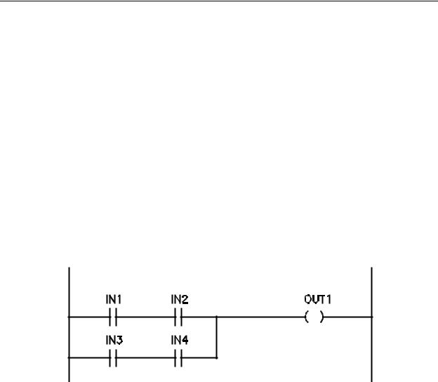
Now consider the ladder diagram of Figure 5-4, a more complicated AND-OR-AND logic containing two branches.
Figure 5-4 - Ladder Diagram AND - OR - AND Function
The previous examples have had only a single branch in each case. A branch may be defined as a single logic expression contained in the overall Boolean expression for a rung. In the case of Figure 5-4, the Boolean expression would be that of Equation 5-1. As can be seen in the Boolean equation, there are two logic expressions OR'ed together; IN1 AND IN2 and IN3 AND IN4. Each of the two expressions is called a branch of logic and must be handled carefully when being input into the controller. Incorrect entering of branches will result in improper (possibly dangerous) operation of the PLC. In cases where entering a branch incorrectly violates the controller logic internally, an error message will be generated and the entry disallowed. In cases where the entry does not violate controller logic, operation will be allowed and could cause bodily injury to personnel if the controller is in a position to operate dangerous machinery.
5-5

Chapter 5 - Mnemonic Programming Code
OUT1 = (IN1)(IN2) + (IN3)(IN4) |
(5-1) |
This configuration of logic in Figure 5-4 utilizes four contacts, IN1, IN2, IN3 and IN4 controlling an output coil OUT1. As discussed in earlier chapters, coil OUT1 will energize when (IN1 AND IN2) OR (IN3 AND IN4) is true. The first line (IN1 AND IN2) is entered in the same manner as described in the previous examples:
(the 1. and 2. are line numbers for our reference only)
1. LD IN1 ENTER
2.AND IN2 ENTER
For the next line (IN3 AND IN4) we must start a new branch. This is accomplished through the use of another LD statement and a portion of PLC memory called the stack.
As program commands for a rung are entered into the PLC they go into what we will call an active memory area. There is another memory area set aside for temporarily storing portions of the commands being input. This area is called the Stack. Each time and LD command is input, the controller transfers all logic currently in the active area to the Stack.
When the first LD command of the rung is input, there is nothing in the active area to transfer to the stack. The next two lines of code would be as follows:
3. LD IN3 ENTER
4.AND IN4 ENTER
The LD command for IN3 causes the previous two lines of code (lines 1 and 2) to be transferred to the Stack. After lines 3 and 4 have been input, lines 1 and 2 will be in the stack and lines 3 and 4 will be in the active memory area.
The two areas, active and the stack, may now be OR'ed with each other using the command OR LD. This tells the controller to retrieve the commands from the stack and OR that code with what is in the active area. The resulting expression is left in the active area.
This line of code would be input as shown below:
5. OR LD ENTER
Up to now, most controllers would have recognized the same type of commands
(AND, OR). The LD and OR LD commands will, however appear differently in various controllers depending upon how the manufacturer wishes to design the controller. For instance, the Allen Bradley SLC-100 handles branches using branch open and branch
5-6
Chapter 5 - Mnemonic Programming Code
close commands instead of OR LD. Mitsubishi controllers use OR BLK instead of OR LD.
Some controllers will use STR in place of LD. Also, in some cases all coils may be entered as OUT with an associated number that specifies it as an output or internal coil. The concept is generally the same, but commands vary with controller manufacturer type and even by model in some units.
Adding the coil command for the ladder diagram of Figure 5-4, the commands required are as follows:
1. |
LD |
IN1 |
ENTER |
2. |
AND |
IN2 |
ENTER |
3. |
LD |
IN3 |
ENTER |
4. |
AND |
IN4 |
ENTER |
5. |
OR |
LD |
ENTER |
6.STO OUT1 ENTER
As a matter of comparison, if the above program had been input into a controller that utilizes STR instead of LD and OUT instead of STO, the commands would be as below:
STR IN1 ENTER
AND IN2 ENTER
STR IN3 ENTER
AND IN4 ENTER
OR STR ENTER
OUT 101 ENTER
The 101 associated with the OUT statement designates the coil as number 101, which, in the case of this particular PLC would, by PLC design, cause it to be an internal or output coil as defined by the PLC manufacturer. As can be seen, the structure is the same but with different commands as required by the PLC being used.
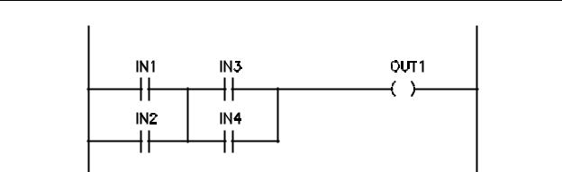
Let us now discuss the ladder rung of Figure 5-5. Recall that this is an OR-AND-OR logic rung having a Boolean expression as shown in Equation 5-2.
OUT1 = (IN1+ IN2)(IN3 + IN4) |
(5-2) |
Two branches can be seen in this expression; (IN1 OR IN2) and (IN3 OR IN4).
These two branches are to be AND'ed together.
5-7
Chapter 5 - Mnemonic Programming Code
Figure 5-5 - Ladder Diagram to Implement OR - AND - OR
Function
Using the LD and STO commands and the same approach as in the examples above, the command structure would be as follows:
1. |
LD |
IN1 |
ENTER |
2. |
OR |
IN2 |
ENTER |
3. |
LD |
IN3 |
ENTER |
4. |
OR |
IN4 |
ENTER |
5. |
AND |
LD |
ENTER |
6.STO OUT1 ENTER
As in the previous example, the LD command in line 3 causes lines 1 and 2 to be transferred to the stack. Line 5 causes the active area and stack to be AND'ed with each other.
5-7. Complex Branches
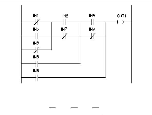
Now that we have discussed basic AND and OR techniques and simple branches, let us look at a rung with a more complex logic expression to illustrate how multiple branches would be programmed. Consider the rung of Figure 5-6. As can be seen, there are multiple logic expressions contained in the overall ladder rung. The Boolean expression for this rung is shown in Equation 5-3.
5-8
Chapter 5 - Mnemonic Programming Code
Figure 5-6 - Complex Ladder Rung
OUT1= ((((IN1+ IN3+ IN8)(IN2 + IN7))
(5-3)
+IN5)(IN 4 + IN 9)) + IN 6
To develop the program commands for this logic, we will begin with the innermost logic expression. This is IN1' + IN3 + IN8'. The commands to enter this expression are:
1. |
LD |
NOT IN1 |
ENTER |
2. |
OR |
IN3 |
ENTER |
3. |
OR |
NOT IN8 |
ENTER |
The next expression to enter is IN2 + IN7', which must be AND'ed with the expression now in the active area. To accomplish this, the logic in the active area must be transferred to the stack, the next expression entered, and then AND'ed with the stack. The command lines for this are:
5-9

Chapter 5 - Mnemonic Programming Code
4. |
LD |
IN2 |
ENTER |
5. |
OR |
NOT IN7 |
ENTER |
6. |
AND |
LD |
ENTER |
Line 4 places the previous expression in the stack and begins the new expression and line
5 completes the new expression. Line 6 causes the stack logic to be retrieved and AND'ed with the active area with the result left in the active area. Referring to Equation 5-3 notice that the expression now located in the active area must now be OR'ed with IN5. This is a simple OR command since the first part of the OR is already in the active area. The command to accomplish this is:
7. OR IN5 |
ENTER |
Now the active area contains:
{(IN1' + IN3 + IN8') (IN2 + IN7')} + IN5
This must be AND'ed with (IN4 + IN9'). To input this expression we must transfer the logic in the active area to the stack, input the new expression, retrieve the stack and AND it with the expression in the active area. These commands are:
8. |
LD |
IN4 |
ENTER |
9. |
OR |
NOT IN9 |
ENTER |
10. |
AND |
LD |
ENTER |
Line 8 transfers the previous expression to the stack and begins input of the new expression, line 9 completes entry of the new expression and line 10 AND's the stack with the new expression. The active area now contains:
(((IN1' + IN3 + IN8') (IN2 + IN7')) + IN5) (IN4 + IN9')
As may be seen in Figure 6-1 - all that remains is to OR this expression with IN6 and add the coil command. The command lines for this are:
11. |
OR |
IN6 |
ENTER |
12. |
STO |
OUT1 |
ENTER |
Combining all the command lines into one set is shown below:
5-10

Chapter 5 - Mnemonic Programming Code
1. |
LD |
NOT IN1 |
ENTER |
2. |
OR |
IN3 |
ENTER |
3. |
OR |
NOT IN8 |
ENTER |
4. |
LD |
IN2 |
ENTER |
5. |
OR |
NOT IN7 |
ENTER |
6. |
AND |
LD |
ENTER |
7. |
OR |
IN5 |
ENTER |
8. |
LD |
IN4 |
ENTER |
9. |
OR |
NOT IN9 |
ENTER |
10. |
AND |
LD |
ENTER |
11. |
OR |
IN6 |
ENTER |
12. |
STO |
OUT1 |
ENTER |
The previous example should be reviewed to be sure operation involving the stack is thoroughly understood.
5-11
Chapter 5 - Mnemonic Programming Code
Chapter 5 Review Question and Problems
1.Draw the ladder diagram and write the mnemonic code for a program that will accept inputs from switches IN1, IN2, IN3, IN4 and IN5 and energize coil OUT123 when one and only one of the inputs is ON.
2.Draw the ladder diagram and write the mnemonic code for an oscillator named CR3.
3.Write the mnemonic code for the J-K Flip Flop.
4.Draw the ladder diagram, assign contact and coil numbers and write the mnemonic code for a T Flip Flop.
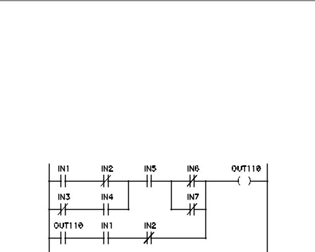
5.Write the mnemonic code for the ladder diagram of Figure 5-7.
Figure 5-7 - Ladder for Problem 5
5-12