


Chapter 5 - Mnemonic Programming Code
Chapter 5 - Mnemonic Programming Code
5-1. Objectives
Upon completion of this chapter, you will know
”why mnemonic code is used in some cases instead of graphical ladder language.
”some of the more commonly used mnemonic codes for AND OR and INVERT operations.
”how to represent ladder branches in mnemonic code.
”how to use stack operations when entering mnemonic coded programs.
5-2. Introduction
All discussions in previous sections have considered only the ladder diagram in all program example development. The next thing to be considered is how to get the ladder diagram into the programmable controller. In higher order controllers, this can be accomplished through the use of dedicated personal computer software that allows the programmer to enter the ladder diagram as drawn. The software then takes care of translating the ladder diagram into the code required by the controller. In the lower order, more basic controllers, this has to be performed by the programmer and entered by hand into the controller. It is this type of language and the procedure for translating the ladder diagram into the required code that will be discussed in this chapter. This will be accomplished by retracing the examples and ladder diagrams developed in earlier chapters and translating them into the mnemonic code required to program a general controller.
This controller will be programmed in a somewhat generic type of code. As the code is learned, comparisons will be presented with similar types of statements found in controller use. The student will have only to adapt to the statements required by the type of controller being used to develop a program for that controller.
5-3. AND Ladder Rung
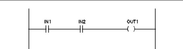
Let us begin with the ladder diagram of Figure 5-1. This is the AND combination of two contacts, IN1 and IN2 controlling coil OUT1.
5-1
Chapter 5 - Mnemonic Programming Code
Figure 5-1 - Ladder Diagram for AND Function
Ladder diagrams are made up of branches of contact logic connected together which control a coil. For instance, IN1 AND IN2 can be considered a branch. This rung has only one branch. We will see examples of multiple branches later. The code command which alerts the controller to the beginning of a branch is LD. The LD command tells the controller that the following set of contacts composes one branch of logic. The complete contact command code for these is:
LD IN1
AND IN2
The lines tell the controller to start a branch with IN1 and with this contact, AND contact IN2. LD commands are terminated with either another LD command or a coil command. In this case, a coil command would terminate because there are no more contacts contained in the ladder. The coil command is STO. The contact and coil commands for this rung of logic are:
LD IN1
AND IN2
STO OUT1
The STO command tells the controller that the previous logic is to control the coil that follows the STO command. Each line of code must be input into the controller as an individual command. The termination command for a line of code is generally ENTER.
NOTE: Two types of terminators have been described and should not be confused with each other. Commands are terminated by another command (a software item) while lines are terminated with ENTER (a hardware keyboard key).
5-2
Chapter 5 - Mnemonic Programming Code
The complete command listing for this ladder rung including termination commands is:
LD IN1 ENTER
AND IN2 ENTER
STO OUT1 ENTER
The commands may be entered using a hand-held programmer, dedicated desktop programmer or a computer containing software that will allow it to operate as a programming device. Each controller command line contains (1) a command, (2) the object of the command and (3) a terminator (the ENTER key). In the case of the first line, LD is the command, IN1 is the object of the command and the ENTER key is the terminator.
Each line of code will typically consume one word of memory, although some of the more complicated commands will consume more than one word. Examples of commands that may consume more than one word of memory are math functions and timers, which will be discussed later.
5-4. Handling Normally Closed Contacts
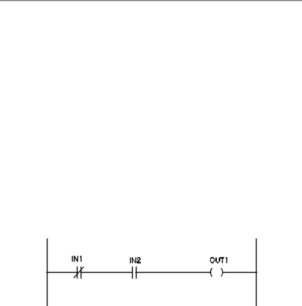
Notice that the rung of Figure 5-1 has only normally open contacts and no normally closed contacts. Let us look at how the command lines would change with the inclusion of a normally closed contact in the rung. This is illustrated in Figure 5-2. Notice that normally open contact IN1 of Figure 5-2 has been replaced with normally closed contact
IN1.
Figure 5-2 - Rung With Normally Closed Contact
To indicate a normally closed contact to the PLC, the term NOT is associated with the contact number. This may take different forms in different controllers depending on the program method used by the manufacturer. Using the same form as in the previous example, the command lines for this rung would appear as follows:
5-3
Chapter 5 - Mnemonic Programming Code
LD |
NOT IN1 |
ENTER |
AND |
IN2 |
ENTER |
STO |
OUT1 |
ENTER |
As stated above, different PLC's may use different commands to perform some functions.
For instance, the Mitsubishi PLC uses the command LDI (LD INVERSE) instead of LD NOT. This requires a single keystroke instead of two keystrokes to input the same command.
If the normally closed contact had been IN2 instead of IN1, the command lines would have to be modified as follows:
LD |
IN1 |
ENTER |
AND |
NOT IN2 |
ENTER |
STO |
OUT1 |
ENTER |
If using the Mitsubishi PLC, the AND NOT command would be replaced with the ANI (AND
INVERSE) command.
5-5. OR Ladder Rung
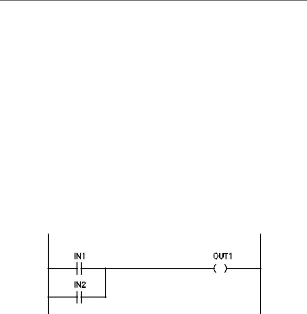
Now, let us translate the ladder of Figure 5-3 into machine code.
Figure 5-3 - Ladder Diagram for OR Function
As can be seen, the contact logic for Figure 5-3 is an OR connection controlling coil OUT1. Following the same steps as with Figure 5-1, the command lines for this rung are:
5-4