

Chapter 4 - Advanced Programming Techniques
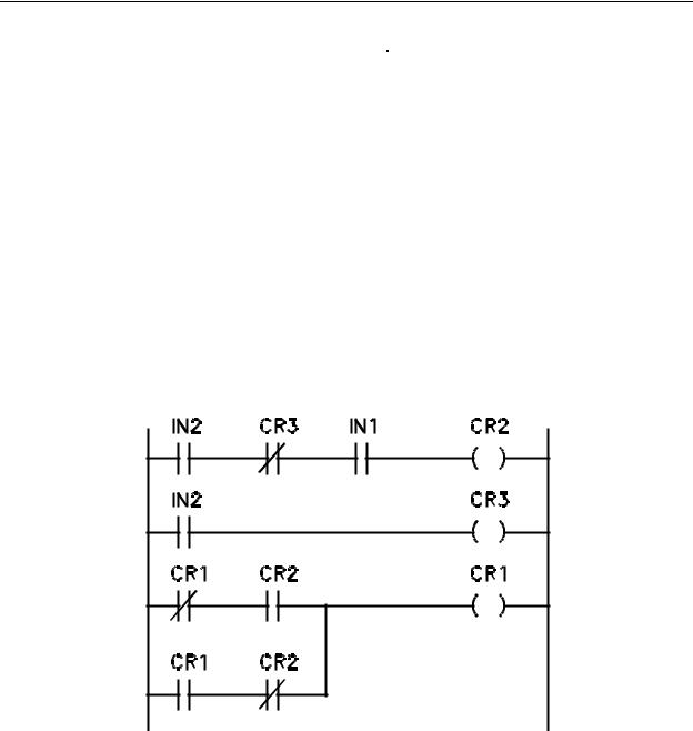
Figure 4-6 - Ladder Diagram for D Flip Flop with
Single Scan Trigger, IN1 = D, IN2 = Trigger
You will see that the D flip flop has the same look as before with a different contact name for the trigger. Previously, the trigger was an input contact, now it is an internal coil CR2.
The first and second rungs are the externally triggered one shot of the type discussed with
Figure 4-4. The input contact in this example has been changed to IN2 and the one shot coil is now CR2. Each time IN2 is turned on, coil CR2 will energize for one scan only. The action on the flip flop will be the same as if the trigger input (IN2) of Table 4-2 were turned on for one scan and turned off for the very next scan, something that is almost if not totally impossible to accomplish with mechanical pushbutton switches. Keep in mind that the trigger contact that initiates the one shot function could be a contact from a coil within the ladder. This would allow the ladder itself to control the flip flop operation inside the program.
4-8. T Flip Flop
The T type flip flop also has two inputs. The clock input performs the same type function as in the D flip flop. It initiates the flip flop action. The second input, however, is unlike the D flip flop. The second input to a T flip flop (the T input) enables or disables the trigger operation (as opposed to a trigger clock signal in the previous discussion). A T flip flop will remain in it's present state upon the application of a clock signal if the T input is a 0. If the T input is a 1, the flip flop will toggle to the other state upon application of a clock signal. The truth table for this flip flop is shown in Table 4-3.
4-9
Chapter 4 - Advanced Programming Techniques
|
|
|
|
T |
CL |
Qn |
Qn+1 |
|
|
|
|
0 |
0 |
X |
Qn |
0 |
1 |
X |
Qn |
1 |
0 |
Q |
Qn |
1 |
1 |
Q |
Qn' |
|
|
|
|
Table 4-3 - Truth Table
for T Flip Flop
A 1 in the CL (clock) column indicates that the clock makes a 0 to 1 to 0 transition.
The Qn column is the state of the flip flop prior to the application of the clock and the Qn+1 column is the state of the flip flop after the clock. An X in the table indicates a don't care
condition. The ladder diagram of a T Flip Flop is shown in Figure 4-7.
Figure 4-7 - Ladder Diagram for a T Flip Flop
IN1 = T, IN2 = Trigger
The T flip flop is formed by all three rungs. The method is to use a toggling coil
(CR1) and a one shot. The one shot is composed of the first and second rungs. The one shot portion of the ladder is very similar to the one of Figure 4-4 except that the one of Table 4-3 is triggered by IN2 instead of IN1 and there is an additional normally open
4-10

Chapter 4 - Advanced Programming Techniques
contact (IN1) in the first rung. The purpose of the normally open IN1 contact is to provide for the T input to the flip flop network. Remember that the T input controls whether the flip flop will toggle or not. If T is a 1, the flip flop will toggle and if T is a 0, the flip flop will not toggle. In the ladder of Table 4-3, The one shot will not trigger if IN1 is a zero because rung one will not have a contact logic that is true if IN1 is not a 1. As we will shortly discuss, the coil of rung 3 (CR1) will not toggle if IN1 does not enable the triggering of the one shot. The contact logic for rung three has two branches, one containing the AND combination of a normally closed CR1 contact and a normally open CR2 contact. The lower branch contains the AND combination of a normally open CR1 contact and a normally closed CR2 contact. The two AND contact combinations are OR'ed together to form the total contact logic for the toggle coil CR1. If IN1 and IN2 are both true at the I/O update, the one shot will trigger just as in our previous discussion of one shot operation. If this is the case, one shot coil CR2 will be energized for only the first scan after that I/O update. If IN1 is not true when IN2 attempts to trigger the toggle flip flop, one shot coil CR2 will not energize at all. Let us assume that toggle coil CR1 is de-energized and that one shot coil CR2 has been enabled and is on for the one scan presently being executed. When the controller arrives at rung three and solves the contact logic, the upper branch will be true because coil CR1 is de-energized making normally closed contact CR1 closed and the normally open CR2 contact will be closed (CR2 is energized for this scan). This will result in the controller energizing coil CR1. On the second and all other scans after IN2 turns on, coil CR2 will be de-energized. On these scans, when the controller arrives at the third rung, the lower branch of contact logic will be true. This is because CR1 is energized and CR2 is de-energized. IN2 must turn off and then back on for the toggle to operate once more. When this occurs, one shot coil CR2 will again be on for the first scan after IN2 turns on, assuming that IN1 was on at the time. When the controller solves the contact logic of rung three on this scan the upper branch will be false because CR1 is energized and the lower branch will be false because one shot coil CR2 is energized. This will cause toggle coil CR1 to de-energize. On the second and all other scans after IN2 turns on, both branches will still be false, the upper because coil CR2 is de-energized and the lower because coil CR1 is de-energized. The rung will continue to be solved with this result until the one shot coil CR2 is again energized for the one scan after IN2 turns on with IN1 on.
4-9. J-K Flip Flop
The last flip flop implementation we will discuss is the J-K Flip Flop. The truth table for such a device is shown in Table 4-4.
4-11
Chapter 4 - Advanced Programming Techniques
|
|
|
|
|
J |
K |
CL |
Qn |
Qn+1 |
|
|
|
|
|
0 |
0 |
1 |
Qn |
Qn |
0 |
1 |
1 |
X |
0 |
1 |
0 |
1 |
X |
1 |
1 |
1 |
1 |
Qn |
Qn' |
X |
X |
0 |
Qn |
Qn |
|
|
|
|
|
Table 4-4 - Truth Table for J-K
Flip Flop
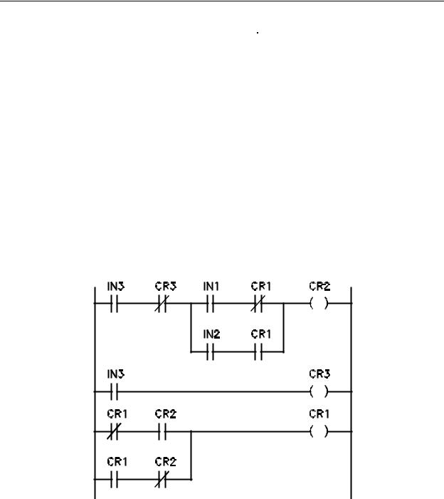
An X in any block indicates a don't care condition. A 1 in the CL (clock) column indicates the clock makes a 0 to 1 to 0 transition. A 0 in the CL column indicates no clock transition. The Qn column contains the flip flop state prior to the application of a clock and the Qn+1 column contains the flip flop state after the clock. The ladder diagram for a J-K Flip Flop in which IN1 = J, IN2 = K and IN3 = CL is shown in Figure 4-8.
Figure 4-8 -
Ladder Diagram for a JK Flip Flop
IN1 = J, IN2 = K, IN3 = Trigger
4-12

Chapter 4 - Advanced Programming Techniques
As with the T flip Flop, this function is composed of three rungs of logic, the first and second being a one shot circuit. As with the T flip flop, the third rung is the flip flop itself. In this case, it happens to be a toggling coil (CR1). Whether the coil toggles or not is decided upon in the first rung by the OR combination of normally open IN1 AND normally closed CR1 contacts with normally open IN2 AND normally open CR1 contacts. This combination was not placed there by accident. This was developed by deciding upon a T type flip flop as the basic function and using logic to determine if the flip flop should toggle or not. If the truth table for a J-K flip flop is studied in a boolean manner using J, K and Q as inputs to the boolean logic, you will find that the flip flop will toggle according to the
Boolean equation T (toggle) = K Q = J Q'. Let's develop this expression to illustrate how Boolean logic and ladder logic can work together.
Note that in Table 4-4 there are don't care states included in the table. A don't care state in binary describes two possible states, the case when the signal is a 1 and the case when the signal is a 0. Also, there are locations in the truth table that show a present state as Qn. This also describes two possible states for that particular signal. If we decide to control a T flip flop in a manner that will simulate the operation of a J-K flip flop, we can do so as long as we define the inputs to the logic and the output of the logic. In the case of our ladder type T flip flop, the output of the logic will need to cause the one shot to trigger since the ladder T flip flop merely toggles whenever the one shot is allowed to trigger. With this being the case, we need only control the one shot portion of the ladder to cause the toggle coil to toggle or not toggle as required by the conditions of a truth table for the device. In this case, it must be a truth table that shows each possible state for all inputs to the logic. Two required inputs to the logic are obviously J and K. However, to decide whether or not to toggle the flip flop, we must know the state of the flip flop at the time. For instance, if Q = 1, J = 1 and K = 0 there is no need to toggle the flip flop because it is a 1 before the clock and needs to be a 1 after the clock. On the other hand, if Q = 1, J = 0 and K = 1 the flip flop needs to switch to a 0 so we have to toggle it. If we develop a truth table taking all possible states of J, K and Q into account, it will look like Table 4-5.
4-13

Chapter 4 - Advanced Programming Techniques
|
|
|
|
J |
K |
Q |
T |
|
|
|
|
0 |
0 |
0 |
0 |
0 |
0 |
1 |
0 |
0 |
1 |
0 |
0 |
0 |
1 |
1 |
1 |
1 |
0 |
0 |
1 |
1 |
0 |
1 |
0 |
1 |
1 |
0 |
1 |
1 |
1 |
1 |
1 |
|
|
|
|
Table 4-5 - Truth
Table for R-S Flip
Flop Using a T Flip
Flop
The J, K and Q columns account for all possible states of the three inputs and the
T column indicates whether the flip flop must toggle. If T is a 1, the one shot function must be allowed to occur upon the turning on of IN3. The Karnough Map representing this truth table with the input states filled in is shown in Table 4-6.
|
|
JK |
|
|
Q |
00 |
01 |
11 |
10 |
0 |
|
|
1 |
1 |
1 |
|
1 |
1 |
|
Table 4-6 - Karnaugh Map for
Table 4-5
From the map, the simplified equation for the trigger enable will be T = KQ + J Q .
4-14